ADB9ZWNX700BNAVTEX RECEIVER
Furuno USA Inc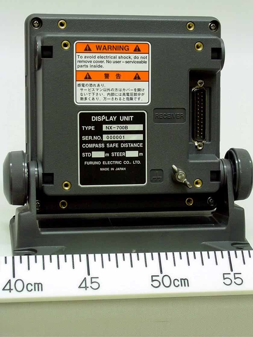
Click to zoom
Application Details
- Equipment Class
- RNV - Part 80 NAVTEX Receiver
- Date of Grant
- Sep 29, 2005
- Application Purpose
- Original Equipment
- Date of Application
- Jun 20, 2005
- Equipment Note
- NAVTEX RECEIVER
- Frequency Range
- 0.51800000 - 4.29500000
- Company
- Furuno USA Inc
- Country
- United States
Documents & Files
Document Text
Text extracted from the exhibit documents filed with the FCC. Open a document above to read the original.
Users Manual
NAVTEX RECEIVER NX-700A/B i IMPORTANT NOTICE • No part of this manual may be copied or reproduced without written permission. • If this manual is lost or worn, contact your dealer about replacement. • The contents of this manual and equipment specifications are subject to change without notice. • The example screens (or illustrations) shown in this manual may not match the screens you see on your display. The screen you see depends on your system configuration and equipment settings. • This manual is intended for use by native speakers of English. • FURUNO will assume no responsibility for the damage caused by improper use or modification of the equipment or claims of loss of profit by a third party. • Please carefully read and follow the operation and maintenance procedures set forth in this manual. • Store this manual in a convenient place for further reference. ii SAFETY INSTRUCTIONS WARNING Do not disassemble or modify the equipment. Fire, electrical shock or serious injury can result. Immediately turn off the power at the switchboard if the equipment is emitting smoke or fire. Continued use of the equipment can cause fire or electrical shock. Contact a FURUNO agent for service. Keep heater away from equipment. A heater can melt the equipment's power cord, which can cause fire or electrical shock. Use the proper fuse. Fuse rating is shown on the equipment. Use of a wrong fuse can result in damage to the equipment. ELECTRICAL SHOCK HAZARD Do not open the equipment. Only qualified personnel should work inside the equipment. CAUTION A warning label is attached to the equip- ment. Do not remove the label. If the label is missing or damaged, contact a FURUNO agent or dealer about replacement. WARNING To avoid electrical shock, do not remove cover. No user-serviceable parts inside. Name: Warning Label (1) Type: 86-003-1011-1 Code No.: 100-236-231 Safety information for the Operator iii Do not open the equipment unless totally familiar with electrical circuits and service manual. Only qualified personnel should work inside the equipment. WARNINGWARNING Turn off the power at the mains switch- board before beginning the installation. Fire, electrical shock or serious injury can result if the power is left on or is applied while the equipment is being installed. ELECTRICAL SHOCK HAZARD Standard Steering Observe the following compass safe distances to prevent deviation of a magnetic compass. CAUTIONCAUTION Display unit Receiver unit NX-7001 Safety information for the Installer NX-700A NX-700B 1.45 m 0.95 m 0.30 m0.30 m 1.15 m 0.75 m Attach securely protective earth to the ship's body. The protective earth is required to the power supply to prevent electrical shock. i v FORWORD Congratulations on your choice of the FURUNO NX-700A/B NVTEX Receiver. We are confident that you will enjoy many years of operation with this fine piece of equipment. For over 50 years, Furuno Electric Company has enjoyed an enviable reputation for quality and reliability throughout the world. Our extensive global network of agents and dealers furthers this dedication to excellence. The NX-700A/B is just one of the many Furuno developments in the field of marine radio communication. NX-700A: Display unit w/printer NX-700B: Display unit w/o printer This NX-700A/B provides cost-effective price, high sensitivity and simple operation in one compact and light-weight unit. In addition to its fundamental function of receiving NAVTEX broadcasts, this unit can also function as nav data display when connected to navigation equipment. This unit is designed and constructed to ensure the user many years of trouble-free operation. To obtain full performance from the equipment, however, you should carefully read and follow the recommended procedures for installation, operation and maintenance. No machine can perform its intended functions unless it is installed and maintained properly. Thank you for considering and purchasing FURUNO equipment. v Features NAVTEX (Navigational Telex) is a world wide coastal telex broadcasting system. Coastal NAVTEX broadcasting stations with specific ID’s transmit Navigational warnings. Meteorological warnings, Search and Rescue (SAR) information and other navigational information for NAVTEX receiver-equipped vessels sailing in coastal waters. The FURUNO NX-700 NAVTEX receiver receives NAVTEX messages and automatically displays them together with station ID and message category information. If ship’s position data is fed from navigation equipment, the NX-700 automatically decides in which NAVAREA the vessel is navigating, and selects stations. (NAVAREAs are geographical zones defined by the international Maritime Organization.) -Meets the following standards and regulations MSC.148 (77) IMO A.694 (17) IEC 61097-6 Ed.2 CDV (2005-02) IEC 60945 Ed. 3 and 4 IEC 61162-1 and 2 EN 300 065V 1.1.3 EN 301 011V 1.1.1 (1998-09) ITU-R M 540-2 ITU-R M 625-3 -Receives 518 kHz and another (490 or 4209.5 kHz) at the same time -5” LCD display -Prints out the message selected -Bright 76 x 100 mm, monochrome LCD, 240 x 320 dots with adjustable contrast and brilliance -Low power consumption -Displays the NAV data or distance information at the bottom of screen -Compact, stylish display, receiver and antenna units vi TABLE OF CONTENTS EQUIPMENT LISTS ............................................................................................. vi SYSTEM CONFIGURATIONS ........................................................................... viii 1. PRINCIPLE OF NAVTEX SYSTEM ............................................................... 1-1 1.1 How NAVTEX Works ................................................................................................. 1-1 1.2 NAVTEX System Operation....................................................................................... 1-1 1.3 Message Format .......................................................................................................1-2 1.4 NAVTEX Station Map …
Text truncated - open the document above for the full version.
Cover Letter(s)
Federal Communications Commission Office of Engineering and Technology 445 12th Street, SW Washington, DC 20554 Request for Confidentiality Dear Sir or Madam, In regard to the FCC application for ID ADB9ZWNX700B. The following documents are company confidential, containing technical information of a proprietary nature. Schematic Diagrams I respectfully request that documents of this category be kept confidential. Thank you for you assistance. Best regards, Shane Ryan Type Acceptance Commercial Service FURUNO USA Inc. (360) 834-9300 X5060 (360) 834- 833-5195 [email protected]
External Photos
Furuno Labotech International Co., Ltd Document number: FLI 01-05-010 Date of issue: 12 May 2005 - Page 1 of 22 - Photographs of NAVTEX RECEIVER NX-700A, NX-700B 1 Display unit NX-700A 1.1 Front view (showing Name Plate and Warning Label on Top Cover) Furuno Labotech International Co., Ltd Document number: FLI 01-05-010 Date of issue: 12 May 2005 - Page 2 of 22 - 1.2 Rear view Furuno Labotech International Co., Ltd Document number: FLI 01-05-010 Date of issue: 12 May 2005 - Page 9 of 22 - 1.9 Name Plate and Warning Label
External Photos
Furuno Labotech International Co., Ltd Document number: FLI 01-05-010 Date of issue: 12 May 2005 - Page 10 of 22 - 2 Display unit NX-700B 2.1 Front view Furuno Labotech International Co., Ltd Document number: FLI 01-05-010 Date of issue: 12 May 2005 - Page 11 of 22 - 2.2 Rear view (showing Name Plate and Warning Label)
External Photos
Furuno Labotech International Co., Ltd Document number: FLI 01-05-010 Date of issue: 12 May 2005 - Page 15 of 22 - 3 Receiver unit NX-7001 3.1 Outside view (showing Name Plate)
External Photos
Furuno Labotech International Co., Ltd Document number: FLI 01-05-010 Date of issue: 12 May 2005 - Page 19 of 22 - 4 Antenna Unit NX-7H 4.1 Outside view
Internal Photos
Furuno Labotech International Co., Ltd Document number: FLI 01-05-010 Date of issue: 12 May 2005 - Page 3 of 22 - 1.3 Inside view (with Rear Cover removed, showing Printer module μTP-58E-FU (upper) Furuno Labotech International Co., Ltd Document number: FLI 01-05-010 Date of issue: 12 May 2005 - Page 4 of 22 - 1.4 Inside view (with PWR Board chassis removed, showing PWR Board 08P3226 (lower left) and Display module (lower right)). Note: The inner part of Display module (lower right) was identical with those of Display unit NX-700B. See Clause 2 Display unit NX-700B of this report for details. Furuno Labotech International Co., Ltd Document number: FLI 01-05-010 Date of issue: 12 May 2005 - Page 5 of 22 - 1.5 PWR Board 08P3226 Front side Furuno Labotech International Co., Ltd Document number: FLI 01-05-010 Date of issue: 12 May 2005 - Page 6 of 22 - 1.6 PWR Board 08P3226 Rear side Furuno Labotech International Co., Ltd Document number: FLI 01-05-010 Date of issue: 12 May 2005 - Page 7 of 22 - 1.7 Printer module μTP-58E-FU Rear side Furuno Labotech International Co., Ltd Document number: FLI 01-05-010 Date of issue: 12 May 2005 - Page 8 of 22 - 1.8 Printer module μTP-58E-FU Front side
Internal Photos
Furuno Labotech International Co., Ltd Document number: FLI 01-05-010 Date of issue: 12 May 2005 - Page 12 of 22 - 2.3 Inside view (with Rear Cover opened, showing CPU Board 08P3225) Furuno Labotech International Co., Ltd Document number: FLI 01-05-010 Date of issue: 12 May 2005 - Page 13 of 22 - 2.4 CPU Board 08P3225 Rear side Furuno Labotech International Co., Ltd Document number: FLI 01-05-010 Date of issue: 12 May 2005 - Page 14 of 22 - 2.5 Inside view (showing LCD module)
Internal Photos
Furuno Labotech International Co., Ltd Document number: FLI 01-05-010 Date of issue: 12 May 2005 - Page 16 of 22 - 3.2 Inside view (with Top Cover removed, showing RCV Board 08P3227) Furuno Labotech International Co., Ltd Document number: FLI 01-05-010 Date of issue: 12 May 2005 - Page 17 of 22 - 3.3 RCV Board 08P3227 Front side Furuno Labotech International Co., Ltd Document number: FLI 01-05-010 Date of issue: 12 May 2005 - Page 18 of 22 - 3.4 RCV Board 08P3227 Rear side
Internal Photos
Furuno Labotech International Co., Ltd Document number: FLI 01-05-010 Date of issue: 12 May 2005 - Page 20 of 22 - 4.2 Inside view Furuno Labotech International Co., Ltd Document number: FLI 01-05-010 Date of issue: 12 May 2005 - Page 21 of 22 - 4.3 Inside view Furuno Labotech International Co., Ltd Document number: FLI 01-05-010 Date of issue: 12 May 2005 - Page 22 of 22 - 4.4 Inside view (with Shield Cover removed, showing AMP Board 08P3228)
Test Report
Test report 99624530 based on: Draft IEC 61097-6 Ed.2 (CDV) 02/2005 EN 61162-1 NAVTEX Receiver Furuno NX-700A; NX-700B Report number: 99624530 Contents MAIN MODULE............................................................................................................................................5 1 I NTRODUCTION ....................................................................................................................................5 2 P RODUCT .............................................................................................................................................6 3 T EST SCHEDULE ...................................................................................................................................6 4 P RODUCT DOCUMENTATION .................................................................................................................7 5 O BSERVATIONS AND COMMENTS .........................................................................................................7 6 S UMMARY ............................................................................................................................................7 7 C ONCLUSIONS ......................................................................................................................................8 TEST RESULTS MODULE .........................................................................................................................9 GENERAL INFORMATION .....................................................................................................................10 5 PERFORMANCE REQUIREMENTS .............................................................................................11 5.1 Introduction 11 5.2 General characteristics 11 5.3 Specific characteristics 12 5.3.1 B1 and B2 Characters..........................................................................................................................12 5.3.2 B3 and B4 Characters..........................................................................................................................12 5.3.3 Preamble..............................................................................................................................................12 5.3.4 Repetition of printing/display..............................................................................................................12 5.3.5 Mandatory printing/display.................................................................................................................12 5.3.6 Reception of messages with character errors......................................................................................12 5.3.7 Controls and indicators........................................................................................................................13 5.3.8 Programmable control memories.........................................................................................................13 5.3.9 Alarms.................................................................................................................................................13 5.3.10 Test facilities...................................................................................................................................13 5.4 Interfaces 14 5.5 Receiver 14 5.5.1 Number of receivers ............................................................................................................................14 5.5.2 Receive Frequencies ............................................................................................................................14 5.5.3 Sensitivity ............................................................................................................................................14 5.6 Display 14 5.6.1 User Interface ......................................................................................................................................14 5.6.2 Number of characters display per line .................................................................................................15 5.6.3 Number of lines displayed ...................................................................................................................15 5.6.4 Display requirements ...........................................................................................................................15 5.6.5 Visibility of display .............................................................................................................................15 5.6.6 Automatic line feed .............................................................................................................................15 5.6.7 End of message display .......................................................................................................................15 5.6.8 Corrupt characters ...............................................................................................................................15 5.6.9 Printer interface message selection requirements ................................................................................15 5.7 Integral printer 16 5.7.1 Number of characters printed per line .................................................................................................16 5.7.2 Automatic line feed .............................................................................................................................16 5.7.3 End of message display .......................................................................................................................16 5.7.4 Corrupt characters ...............................................................................................................................16 5.7.5 General printer requirements ...............................................................................................................16 5.7.6 Printer…
Text truncated - open the document above for the full version.
Contact Information
Applicant
Bill Haynes(Deep Sea Product Manager)
Technical Specifications
| # | Rule Parts | Frequency Range | Power Output | Emission |
|---|---|---|---|---|
| 1 | 80.1101(c)(1) | 0.518 MHz - 4.295 MHz | - | N/A |
Other Applications from Furuno USA Inc
ADB-9ZWRTR137
Feb 18, 2026Transceiver unit for the radar sensor
Equipment Class
MRD - Marine RadarADB9ZWRTR136
Jul 01, 2024Transceiver unit for the radar sensor
Equipment Class
MRD - Marine Radar
ADB9ZWRTR128
Apr 06, 2022Transceiver unit for the radar sensor
Equipment Class
MRD - Marine Radar
ADB9ZWRTR133
Sep 26, 2021Transceiver unit for the radar sensor
Equipment Class
MRD - Marine Radar
ADB9ZWRTR129
May 23, 2021Transceiver unit for the radar sensor
Equipment Class
MRD - Marine Radar