ADB9ZWRTR064AMarine Radar
Furuno USA Inc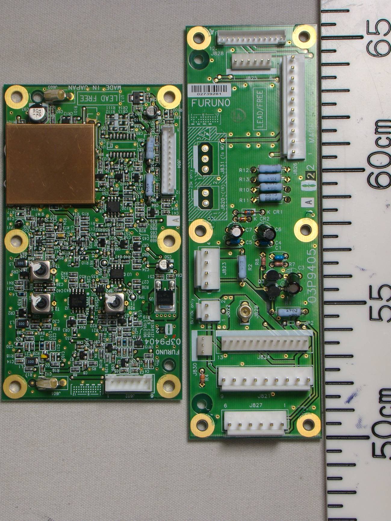
Click to zoom
Application Details
- Equipment Class
- MRD - Marine Radar
- Date of Grant
- May 31, 2011
- Application Purpose
- Original Equipment
- Date of Application
- Apr 27, 2011
- Equipment Note
- Marine Radar
- Frequency Range
- 9300.00000000 - 9500.00000000
- Company
- Furuno USA Inc
- Country
- United States
Documents & Files
Document Text
Text extracted from the exhibit documents filed with the FCC. Open a document above to read the original.
Users Manual
MARINE RADAR MODEL 1835 MODEL 1935 MODEL 1945 OPERATOR'S MANUAL www.furuno.co.jp MODEL *00017024512**00017024512* *00017024512**00017024512* i IMPORTANT NOTICES General • This manual has been authored with simplified grammar, to meet the needs of international us- ers. • The operator of this equipment must read and follow the descriptions in this manual. Wrong op- eration or maintenance can cancel the warranty or cause injury. • Do not copy any part of this manual without written permission from FURUNO. • If this manual is lost or worn, contact your dealer about replacement. • The contents of this manual and equipment specifications can change without notice. • The example screens (or illustrations) shown in this manual can be different from the screens you see on your display. The screens you see depend on your system configuration and equip- ment settings. • Save this manual for future reference. • Any modification of the equipment (including software) by persons not authorized by FURUNO will cancel the warranty. • All brand and product names are trademarks, registered trademarks or service marks of their respective holders. How to discard this product Discard this product according to local regulations for the disposal of industrial waste. For disposal in the USA, see the homepage of the Electronics Industries Alliance (http://www.eiae.org/) for the correct method of disposal. How to discard a used battery Some FURUNO products have a battery(ies). To see if your product has a battery(ies), see the chapter on Maintenance. Follow the instructions below if a battery(ies) is used. In the European Union The crossed-out trash can symbol indicates that all types of batteries must not be discarded in standard trash, or at a trash site. Take the used batteries to a battery collection site according to your national legislation and the Batteries Directive 2006/66/EU. In the USA The Mobius loop symbol (three chasing arrows) indicates that Ni-Cd and lead-acid rechargeable batteries must be recycled. Take the used batteries to a battery collection site according to local laws. In the other countries There are no international standards for the battery recycle symbol. The number of symbols can increase when the other countries make their own recycle symbols in the future. Cd Ni-CdPb ii SAFETY INSTRUCTIONS WARNING Model Distance to 100 W/m 2 point WARNING Indicates a condition that can cause death or serious injury if not avoided. CAUTION Indicates a condition that can cause minor or moderate injury if not avoided. Warning, Caution Mandatory Action Prohibitive Action Read these safety instructions before you operate the equipment. Distance to 50 W/m 2 point 1835 1935 1945 Worst case 0.0 m Worst case 0.2 m Worst case 0.2 m Worst case 0.1 m Radio Frequency Radiation Hazard The radar antenna sends the electromagnetic radio frequency (RF) energy. This energy can be dangerous to you, especially your eyes. Do not look at the radiator or near the antenna when the antenna is rotating. The distances at which RF radiation levels of 100 W/m 2 , 50 W/m 2 and 10 W/m 2 exist are shown in the table. Note: If the antenna unit is installed at a close distance in front of the wheel house, prevent the transmission in that area to protect passengers and crew from microwave radiation. Set the [Sector Blanks] in the [System] menu. Distance to 10 W/m 2 point Worst case 1.0 m Worst case 1.2 m Worst case 1.7 m SAFETY INSTRUCTIONS iii WARNING ELECTRICAL SHOCK HAZARD Do not open the equipment. Only qualified persons can work inside the equipment. Turn off the power before you service the antenna unit. Post a warning sign near the power switch not to turn on the power while you service the antenna unit. Prevent the potential risk of being struck by the rotating antenna and exposure to RF radiation hazard. When you work on the antenna unit, wear a safety belt and hard hat. Serious injury or death can result if a person falls from the radar antenna mast. Do not disassemble or modify the equipment. Fire or electrical shock can occur. Turn off the power immediately if water leaks into the equipment or smoke or fire is coming from the equipment. Failure to turn off the equipment can cause fire or electrical shock. Use the correct fuse. A wrong fuse can damage the equipment and cause fire. Keep heater away from the equipment. Heat can change the equipment shape and meltthe power cord, which can cause fire or electrical shock. Do not put liquid-filled containers on the top of the equipment. Fire or electrical shock can occur if a liquid spills into the equipment. Do not operate the equipment with wet hands. Electrical shock can occur. WARNING SAFETY INSTRUCTIONS iv Do not depend on one navigation device for the navigation of the ship. The navigator must check all aids available to confirm position. Electronic aids are not a replacement for basic navigation principles and common sense. · The ARPA automatically tracks an automatically or manually acquired radar target and calculates its course and speed, indicating them by a vector. Since the data from the auto plotter depend on the selected radar targets, the radar must be optimally tuned for use with the auto plotter, to ensure required targets will not be lost or unnecessary targets like sea returns and noise will not be acquired and tracked. · A target is not always a landmass, reef, ship, but can also be returns from the sea surface and from clutter. As the level of clutter changes with the environment, the operator must correctly adjust the A/C SEA, A/C RAIN and GAIN controls so that the target echoes do not disappear from the radar screen. CAUTIONCAUTION The plotting accuracy and response of this ARPA meets IMO standards. The tracking accuracy is affected by the following: · The tracking accuracy is affected by course change. One to two minutes is required to restore vectors to full accuracy after a sudden course change. (The actual amount depends on gyrocompass specifications.)…
Text truncated - open the document above for the full version.
Users Manual
1. DESCRIPTION OF OPERATION 1-36 1.28Custom Setup 1.28.1About custom setup When your navigating environment or task changes, you must adjust the radar. In- stead of changing radar settings case by case, you can assign the CUSTOM key to provide best settings for common conditions. There are three default custom setups for the internal computer of the radar (see the table on the next page). You can adjust these settings on the [Custom 1], [Custom 2] and [Custom 3] menus to meet your navigation needs. To activate a custom setup, press the CUSTOM key. The CUSTOM key switches be- tween Custom 1, Custom 2 or Custom 3 each time you press the key. (Custom setup numbers which are turned off are ignored.) The selected custom setup name is shown at the upper-left corner. To escape from custom setup, operate any control. 1.28.2Description of custom setup items Description of custom setup items Menu itemAvailable settingsSee section [Custom1(2 or 3)]Turn on/off each custom program. [Copy]Copy settings from the [Echo] menu. The message "Com- plete" appears after the copying is completed. [Gain Mode][Auto]: Automatic gain adjustment according to noise level [Manual]: Manual gain adjustment 1.9 [Manual Gain]Copy the current position of the GAIN knob when you do [Copy]. This item is for read-only. [Sea Mode][Auto]: Automatic sea clutter adjustment according to sea state [Manual]: Manual sea clutter adjustment 1.10 [Auto Sea][Coastal]: Suppress both land and sea clutter. [Advanced]: Automatically discriminate land echoes from sea reflections to suppress only sea reflections. 1.10 [Manual Sea]Copy the current position of the A/C SEA knob when you do [Copy]. This item is for read-only. [Rain Mode][Auto]: Automatic rain clutter adjustment according to rain cloud [Manual]: Manual rain clutter adjustment 1.11 [Auto Rain][Calm]: For light rain [Moderate]: When you can not reduce the rain clutter with [Calm] mode [Rough]: For heavy rain 1.11 [Manual Rain]Copy the current position of the A/C RAIN knob when you do [Copy]. This item is for read-only. [A/C Auto][Off], [On]1.12 1. DESCRIPTION OF OPERATION 1-37 1.28.3How to set custom setups 1. Press the MENU key to open the menu. 2. Use the Cursorpad (S or T) to select [Custom 1 (2 or 3)] and press the ENTER key. Custom menu 3. Set menu items. Note: For easy set up, you can copy the settings of the [Echo] menu (to [Custom 1], [Custom 2], [Custom 3]). Select [Copy] and press the ENTER key. When the copying is completed, the message "Complete" appears. To erase this message, press any key. 4. Press the MENU key to close the menu. [Pulse Length][Short] or [Long], you can select on 1.5, 1.6, 3.0 and 3.2 nm ranges. 1.18 [Echo Stretch][Off], [1], [2], [3]1.22 [Echo Average][Off], [1], [2], [Auto]1.23 [Noise Rejector][Off], [On]1.30 [Wiper][Off], [1], [2]1.31 [Int Rejector][Off], [1], [2], [3]1.14 [Display-Dynamic][Narrow]: Erase weak echoes. [Normal]: Normal use [Wide]: Display weaker echoes compared to [Narrow]. 1.36 [Display-Curve][1]: Reduce weak echoes. [2]: Normal use [3]: Display weaker echoes in stronger color compared to [1]. 1.37 [Color Erase]0 - 111.44.3 Menu itemAvailable settingsSee section 1. DESCRIPTION OF OPERATION 1-38 1.29How to Program Function Keys (F1, F2 and F3 keys) You can program function keys (F1, F2 and F3) to provide one-touch access to a re- quired function. Function key operation To activate a function, press function key, F1, F2 or F3. Press same key to change the setting. The default programs are [Gain Mode] for F1, [Sea Mode] for F2, [A/C Auto] for F3. When you press the F1 or F2 key, the window for Gain/Sea/Rain indicator shows. See section 1.9 and 1.10 for operation. When you press the F3 key, [A/C Auto] is turned on. How to change a function key program 1. Press the MENU key to open the menu. 2. Use the Cursorpad (S or T) to select [Others] and press the ENTER key. 3. Use the Cursorpad (S or T) to select [F1 (F2 or F3) Setup] and press the ENTER key. 4. Use the Cursorpad (S or T) to select a function from the list and press the EN- TER key. Below are the available functions. Function list 5. Press the MENU key to close the menu. Rings Brill Mark Brill HL Brill Character Brill View Position Display Color Echo Color Background Color Character Color Menu Transparency Echo Color Mode Display Mode Zoom Zoom Mode Echo Area Data Box STBY Display Gain Mode Sea Mode Auto Sea Rain Mode Auto Rain A/C Auto Pulse Length Echo Stretch Echo Average Noise Rejector Wiper Int Rejector Display-Dynamic Display-Curve 2nd Echo Rejector Target Alarm 1 Target Alarm 2 Alarm Level Watchman Panel Buzzer External Buzzer Trails-Gradation Trails-Color Trails-Mode Trails-Level Trails-Restart Trails-Narrow Trails-Own Ship Tuning Mode WPT Mark EBL Reference VRM Unit Cursor Position TLL Key Mode Vector Reference History Dots History Interval CPA TCPA Proximity ARPA-Display ARPA-Color ARPA-Auto Acquisition ARPA-ACK Lost Targets AIS-Display AIS-Color AIS-Sort By AIS-ACK Lost Targets GPS-Mode GPS-Datum GPS-WAAS 1. DESCRIPTION OF OPERATION 1-39 1.30Noise Rejector White noise can appear on the screen as random "marks". You can reduce this noise as follows: 1. Press the MENU key to open the menu. 2. Use the Cursorpad (S or T) to select [Echo] and press the ENTER key. 3. Use the Cursorpad (S or T) to select [Noise Rejector] and press the ENTER key. Noise Rejector options 4. Use the Cursorpad (S or T) to select [Off] or [On] then press the ENTER key. 5. Press the MENU key to close the menu. 1.31Wiper The wiper feature automatically reduces the brilliance of unwanted weak signals (noise, sea clutter, rain clutter, etc.) and unnecessary signals, like radar interference, to clear the picture of unnecessary echoes. The result of wiper depends on the wiper setting used and whether echo averaging is turned on or off, as described below. Echo averaging and wiper states and wiper effect Processing content A: The brilliance of unnecessary weak echoes, like noise and radar interference, is …
Text truncated - open the document above for the full version.
Users Manual
4. AIS OPERATION 4-10 4. Use the Cursorpad (S) to select [Yes] and press the ENTER key. All lost targets symbols are erased from the screen and the long beep sounds. 5. Press the MENU key to close the menu. 4.15Symbol Color You can select the AIS symbol color among Green, Red (unavailable in the [IEC] or [Russian-River] purpose), Blue, White or Black. 1. Press the MENU key to open the menu. 2. Use the Cursorpad (S or T) to select [AIS] and press the ENTER key. 3. Use the Cursorpad (S or T) to select [Color] and press the ENTER key. Color options 4. Use the Cursorpad (S or T) to select the color and press the ENTER key. 5. Press the MENU key to close the menu. Note: Symbols can not be shown in the same color as the background color. 4.16How to Ignore Slow Targets You can prevent activation of the CPA/TCPA alarm against AIS targets that are trav- eling at a speed lower than set here. The AIS symbols are not affected by this setting. 1. Press the MENU key to open the menu. 2. Use the Cursorpad (S or T) to select [AIS] and press the ENTER key. 3. Use the Cursorpad (S or T) to select [Ignore Slow Targets] and press the ENTER key. Ignore Slow Targets setting window 4. Use the Cursorpad (S or T) to select speed (0.0 - 9.9 kn) and press the ENTER key. 5. Press the MENU key to close the menu. 5-1 5.GPS OPERATION If the FURUNO GPS Navigator GP-320B is connected to this radar, you can set GP- 320B from this radar. 5.1Navigator Mode 1. Press the MENU key to open the menu. 2. Use the Cursorpad (S or T) to select [GPS] and press the ENTER key. 3. Use the Cursorpad (S or T) to select [Mode] and press the ENTER key. Mode options 4. Use the Cursorpad (S or T) to select [GPS] or [WAAS] then press the ENTER key. 5. Press the MENU key to close the menu. 5.2Datum Select the type of datum which matches the paper charts you use for navigation. Se- lect [WGS-84] if the radar is connected to an AIS Transponder. 1. Press the MENU key to open the menu. 2. Use the Cursorpad (S or T) to select [GPS] and press the ENTER key. 3. Use the Cursorpad (S or T) to select [Datum] and press the ENTER key. Datum options 4. Use the Cursorpad (S or T) to select the type of datum and press the ENTER key. If you select [WGS-84] or [Tokyo], go to step 7. If you select [Other], go to the next step. 5. Use the Cursorpad (S or T) to select [Datum No] and press the ENTER key. Datum No setting window 6. Use the Cursorpad (S or T) to select the datum number and press the ENTER key. (The setting range is 001 - 192 and 201 - 254. Refer to the appendix 2 “GEO- DETIC CHART LIST”.) 7. Press the MENU key to close the menu. 5. GPS OPERATION 5-2 5.3WAAS Setup Geostationary satellites, the type used with WAAS, provide more accurate position data when compared to GPS. These satellites can be tracked automatically or manu- ally. Auto tracking automatically searches for the best geostationary satellite from your current position. 1. Press the MENU key to open the menu. 2. Use the Cursorpad (S or T) to select [GPS] and press the ENTER key. 3. Use the Cursorpad (S or T) to select [WAAS] and press the ENTER key. WAAS options 4. Use the Cursorpad (S or T) to select [Auto] or [Manual] then press the ENTER key. If you select [Auto], go to step 7. If you select [Manual], go to the next step. 5. Use the Cursorpad (S or T) to select [WAAS No] and press the ENTER key. WAAS No setting window 6. Use the Cursorpad (S or T) to select WAAS number and press the ENTER key. (The setting range is 120 - 158. Refer to the following table.) 7. Press the MENU key to close the menu. ProviderSatellite typeLongitudeSatellite No. WAASInmarsat-3-F4 (AOR-W)142°W122 Inmarsat-3-F3 (POR)178°E134 Intelsat Galaxy XV133°W135 TeleSat Anik F1R107.3°W138 EGNOSInmarsat-3-F2 (AOR-E)15.5°W120 Artemis21.5°E124 Inmarsat-3-F5 (IOR-W)25°E126 MSASMTSAT-1R140°E129 MTSAT-2145°E137 5. GPS OPERATION 5-3 5.4Satellite Monitor The Satellite Monitor provides the information about GPS and WAAS satellites. See your GPS navigator's owner's manual for detailed information. 1. Press the MENU key to open the menu. 2. Use the Cursorpad (S or T) to select [GPS] and press the ENTER key. 3. Use the Cursorpad (S or T) to select [Satellite Monitor] and press the ENTER key. Satellite monitor 4. Press the ENTER key to close only the satellite monitor display. 06 W3D DOP 1.5 15m 13 Altitude 01GPS WAAS 12 24 16 SNRSatellite No. 304050 122 01 31 18 19 06 07 09 08 13 North marker DOP (Dilution of Precision, 0.0 - 99.0) SNR of tracked GPS satellites Satellites whose SNR is above 40 are used to fix position. GPS mode 2D, 3D, W2D, W3D GPS satellite no.* WAAS satellite Satellites in ring have elevation angle of 5° Satellites in ring have elevation angle of 45° Altitude of GPS antenna from sea surface SNR of tracked WAAS satellite W N [MENU]: Close MENU [ENTER]: Close this window * Satellites used to fix position are shown in red. Satellite Monitor 01 09 24 12 19 18 07 13 16 08 31 5. GPS OPERATION 5-4 5.5Cold Start Cold start, which clears the Almanac from the GPS receiver, can be necessary in the following conditions: • If you have turned off the power of the GPS receiver for a long time. • The ship has moved far away from the previous fixing position (e.g., more than 500 km). • Other reason that prevents the receiver from finding its position within five minutes after you turn on the power. To do cold start, do the following: 1. Press the MENU key to open the menu. 2. Use the Cursorpad (S or T) to select [GPS] and press the ENTER key. 3. Use the Cursorpad (S or T) to select [Cold Start] and press the ENTER key. Cold Start options 4. Use the Cursorpad (S) to select [Yes] and press the ENTER key. After processing cold start, the long beep sounds. (To stop cold start, press the CANCEL/HL OFF key instead of the ENTER key.) 5. Press the MENU key to close the menu. 6-1 6.MAINTENANCE, TROUBLE- SHOOTING This chapter has information about maintenance and troubleshooting that the user can follow to care for the equipment. WARNING EL…
Text truncated - open the document above for the full version.
Cover Letter(s)
Federal Communications Commission Office of Engineering and Technology 445 12th Street, SW Washington, DC 20554 To whom it may concern, We hereby respectfully request that under the provision of KDB Publication 726920, the following documents submitted in support of this application for ADB9ZWRTR064A certification be provided with confidential status. Schematics Parts list/Tune up info Operational description These documents contain trade secrets that are treated as confidential by us. Substantial competitive harm to our company business could result should they be made available to the public. Best regards , Shane Ryan Type Acceptance Commercial Service FURUNO USA Inc. (360) 834-9300 X5060 (360) 834- 833 -5195 [email protected]
External Photos
Furuno Labotech International Co., Ltd. Document number: FLI 01-10-046 Date of issue: 5 January 2011 - Page 1 of 16 - Photographs of the Antenna unit with the Transceiver RTR-064A included for Furuno Marine Radar MODEL 1935 1 External view 1.1 Front view (with Radiator removed.) Furuno Labotech International Co., Ltd. Document number: FLI 01-10-046 Date of issue: 5 January 2011 - Page 2 of 16 - 1.2 Rear view (with Radiator removed.) ID Label Furuno Labotech International Co., Ltd. Document number: FLI 01-10-046 Date of issue: 5 January 2011 - Page 3 of 16 - 1.3 ID Label Furuno Labotech International Co., Ltd. Document number: FLI 01-10-046 Date of issue: 5 January 2011 - Page 4 of 16 - Photographs of the Antenna unit with the Transceiver RTR-064A included for Furuno Marine Radar MODEL 1935 2 Inside View 2.1 Inside front view (with top lid opened.) Transceiver module Furuno Labotech International Co., Ltd. Document number: FLI 01-10-046 Date of issue: 5 January 2011 - Page 5 of 16 - 2.2 Inside front view RTB Board Furuno Labotech International Co., Ltd. Document number: FLI 01-10-046 Date of issue: 5 January 2011 - Page 6 of 16 - 2.3 Inside front view (with Transceiver module removed.) Furuno Labotech International Co., Ltd. Document number: FLI 01-10-046 Date of issue: 5 January 2011 - Page 7 of 16 - 2.4 Transceiver front view (with shield cover for IF Board 03P9404 removed.) Furuno Labotech International Co., Ltd. Document number: FLI 01-10-046 Date of issue: 5 January 2011 - Page 8 of 16 - 2.5 Transceiver right view Magnetron Furuno Labotech International Co., Ltd. Document number: FLI 01-10-046 Date of issue: 5 January 2011 - Page 9 of 16 - 2.6 Transceiver rear view Magnetron Isolator Filter Circulator Limiter Furuno Labotech International Co., Ltd. Document number: FLI 01-10-046 Date of issue: 5 January 2011 - Page 10 of 16 - 2.7 Transceiver left view MIC Furuno Labotech International Co., Ltd. Document number: FLI 01-10-046 Date of issue: 5 January 2011 - Page 11 of 16 - 2.8 Transceiver bottom view Furuno Labotech International Co., Ltd. Document number: FLI 01-10-046 Date of issue: 5 January 2011 - Page 12 of 16 - 2.9 Transceiver bottom view (with shield cover removed, showing MD Board 03P9235) Furuno Labotech International Co., Ltd. Document number: FLI 01-10-046 Date of issue: 5 January 2011 - Page 13 of 16 - Photographs of the Antenna unit with the Transceiver RTR-064A included for Furuno Marine Radar MODEL 1935 3 PCBs 3.1 MD Board 03P9235 and RRV Board 03P9323 front side RRV Board MD Board Furuno Labotech International Co., Ltd. Document number: FLI 01-10-046 Date of issue: 5 January 2011 - Page 14 of 16 - 3.2 MD Board 03P9235 rear side Furuno Labotech International Co., Ltd. Document number: FLI 01-10-046 Date of issue: 5 January 2011 - Page 15 of 16 - 3.3 IF Board 03P9404 and RTB Board 03P9405 front side Furuno Labotech International Co., Ltd. Document number: FLI 01-10-046 Date of issue: 5 January 2011 - Page 16 of 16 - 3.4 IF Board 03P9404 and RTB Board 03P9405 rear side
ID Label/Location Info
Furuno Labotech International Document number: FLI 01-10-057 Date of issue: 5 January 2011 Form: Q053/01 - Page 1 of 2 - Identification of Equipment for the Furuno Radar Sensor M1935 with Transceiver RTR-064A included (FCC Rule, 2.925) 1 ID Label The following nameplate is permanently fixed on the corresponding equipment unit. FCC ID: ADB9ZWRTR064A Material of Name plate: Polyester film, 0.2 mm thick Furuno Labotech International Document number: FLI 01-10-057 Date of issue: 5 January 2011 Form: Q053/01 - Page 2 of 2 - 2 ID Label Location ID Label is affixed on the Scanner ID Label
Internal Photos
Furuno Labotech International Co., Ltd. Document number: FLI 01-10-046 Date of issue: 5 January 2011 - Page 1 of 16 - Photographs of the Antenna unit with the Transceiver RTR-064A included for Furuno Marine Radar MODEL 1935 1 External view 1.1 Front view (with Radiator removed.) Furuno Labotech International Co., Ltd. Document number: FLI 01-10-046 Date of issue: 5 January 2011 - Page 2 of 16 - 1.2 Rear view (with Radiator removed.) ID Label Furuno Labotech International Co., Ltd. Document number: FLI 01-10-046 Date of issue: 5 January 2011 - Page 3 of 16 - 1.3 ID Label Furuno Labotech International Co., Ltd. Document number: FLI 01-10-046 Date of issue: 5 January 2011 - Page 4 of 16 - Photographs of the Antenna unit with the Transceiver RTR-064A included for Furuno Marine Radar MODEL 1935 2 Inside View 2.1 Inside front view (with top lid opened.) Transceiver module Furuno Labotech International Co., Ltd. Document number: FLI 01-10-046 Date of issue: 5 January 2011 - Page 5 of 16 - 2.2 Inside front view RTB Board Furuno Labotech International Co., Ltd. Document number: FLI 01-10-046 Date of issue: 5 January 2011 - Page 6 of 16 - 2.3 Inside front view (with Transceiver module removed.) Furuno Labotech International Co., Ltd. Document number: FLI 01-10-046 Date of issue: 5 January 2011 - Page 7 of 16 - 2.4 Transceiver front view (with shield cover for IF Board 03P9404 removed.) Furuno Labotech International Co., Ltd. Document number: FLI 01-10-046 Date of issue: 5 January 2011 - Page 8 of 16 - 2.5 Transceiver right view Magnetron Furuno Labotech International Co., Ltd. Document number: FLI 01-10-046 Date of issue: 5 January 2011 - Page 9 of 16 - 2.6 Transceiver rear view Magnetron Isolator Filter Circulator Limiter Furuno Labotech International Co., Ltd. Document number: FLI 01-10-046 Date of issue: 5 January 2011 - Page 10 of 16 - 2.7 Transceiver left view MIC Furuno Labotech International Co., Ltd. Document number: FLI 01-10-046 Date of issue: 5 January 2011 - Page 11 of 16 - 2.8 Transceiver bottom view Furuno Labotech International Co., Ltd. Document number: FLI 01-10-046 Date of issue: 5 January 2011 - Page 12 of 16 - 2.9 Transceiver bottom view (with shield cover removed, showing MD Board 03P9235) Furuno Labotech International Co., Ltd. Document number: FLI 01-10-046 Date of issue: 5 January 2011 - Page 13 of 16 - Photographs of the Antenna unit with the Transceiver RTR-064A included for Furuno Marine Radar MODEL 1935 3 PCBs 3.1 MD Board 03P9235 and RRV Board 03P9323 front side RRV Board MD Board Furuno Labotech International Co., Ltd. Document number: FLI 01-10-046 Date of issue: 5 January 2011 - Page 14 of 16 - 3.2 MD Board 03P9235 rear side Furuno Labotech International Co., Ltd. Document number: FLI 01-10-046 Date of issue: 5 January 2011 - Page 15 of 16 - 3.3 IF Board 03P9404 and RTB Board 03P9405 front side Furuno Labotech International Co., Ltd. Document number: FLI 01-10-046 Date of issue: 5 January 2011 - Page 16 of 16 - 3.4 IF Board 03P9404 and RTB Board 03P9405 rear side
Test Report
This report shall not be reproduced except in full, without the written approval of Furuno Labotech International Co., Ltd. Test Report (FCC Rules 2.1046/2.1047/2.1049/2.1051/2.1053/2.1055/80.217) For Trade name: Furuno Model: Transceiver for Marine Radar Type: RTR-064A Report no.: FLI 12-10-078 Date of issue: 5 January 2011 Furuno Labotech International Co., Ltd. 9-52 Ashihara-cho, Nishinomiya City, Hyogo 662-8580, Japan Tel: +81-798-63-1094 Fax: +81-798-63-1098 Furuno Labotech International Report no.: FLI 12-10-078 Form: FQ053/04 - Page 2 of 35 - Report Summary FLI project number: FLI 04-10-0340 Test report number: FLI 12-10-078 Date of Initial Issue: 5 January 2011 Revision number: --- Date of Revised Issue: --- Test report revision made: Rev. no. Date PageItemDescription of change --- --- --- --- --- Test standard(s)/ Test specifications: FCC 47 CFR, Sections: 2.1046 - RF Power Output, 2.1047 - Modulation Characteristics, 2.1049 - Occupied Bandwidth, 2.1051 - Spurious Emissions at Antenna Terminal, 2.1055 - Frequency Stability, 2.1053 - Field Strength of Spurious Radiation, 80.217 - Suppression of Interference Aboard Ships. (Date of issue: 1 October 2008) Customer: Furuno Electric Co., Ltd. 9-52 Ashihara-Cho, Nishinomiya-City, 662-8580 Japan Manufacturer: Furuno Electric Co., Ltd. 9-52 Ashihara-Cho, Nishinomiya-City, 662-8580 Japan Trade name: FURUNO Model: Transceiver for Marine Radar Type: RTR-064A Product function and intended use: For Marine Safety navigation Number of samples tested: One Serial number: 4395-0001 Power rating: 12 - 24 VDC, 85 – 105 W (for Display Unit RDP-152) (The EUT was powered through the Display unit, not directly from DC mains) Product status: Pre-production model Modifications made to samples during testing: None. Date of receipt of samples: 23 August 2010 Test period: 24 August 2010 to 4 November 2010 Place of test: Furuno Labotech International Co., Ltd. - Nishinomiya Lab. 9-52 Ashihara-Cho, Nishinomiya City, Hyogo Prefecture, 662-8580 Japan - Nishinomiya-Hama Lab. 2-20 Nishinomiya-Hama, Nishinomiya City, Hyogo Prefecture, 662-0934 Japan Anechoic Chamber used for the test has been registered by FCC. (File number: 90607) Test results/ Compliance: Passed. The test results of this report relate only to the samples tested. Tested by: Katsumi Imamura and Akira Inoue Written by: Akiko Inoue Verified by: Yoshihiro Ishii Approved by: Date: 5 January 2011 Name: Yoshihiro Ishii Title: Manager, Technical Section, Furuno Labotech International Co., Ltd. Signature: Furuno Labotech International Report no.: FLI 12-10-078 Form: FQ053/04 - Page 3 of 35 - Testing Laboratory Status Furuno Labotech International Co., Ltd. (hereafter called FLI) has been holding the following status after having been assessed according to the provisions of ISO/IEC 17025 and/or the relevant rules: (1) Telefication Listed Testing Laboratory: - listed by Telefication B. V., Edisonstraat 12a, 6902 PK Zevenaar, The Netherlands - Laboratory assignment number: L116 - Date of initial certification: 26 July 1999 (*) - for testing the following product categories/ test standards: - EN 60945, Maritime navigation and radiocommunication equipment and systems - General requirements. - IEC 61162-1/-2, Maritime navigation and radiocommunication equipment and systems - Digital interfaces - Part 1: Single talker and multiple listeners / Part 2: Single talker and multiple listeners, high speed transmission. (2) BSH Recognized Testing Laboratory: - recognized by Bundesamt für Seeschifffahrt und Hydrographie, Bernhad-Nocht-Str. 78, 20359 Hamburg, Federal Republic of Germany - Recognition certificate number: BSH4613/06201/0835/08 - Date of initial certification: 4 April 2003 (*) - for testing in the fields of: “Marine navigational and radiocommunication equipment and systems” - EMC and environmental tests according to: IEC 60945: 2002, DIN EN 60945: 2003 - Radar - Shipborne navigational displays IEC 60936-1: 1999, DIN EN 60936-1: 2000 IEC 62288: 2008 IEC 60936-2: 1998, DIN EN 60936-2: 1999 (3) TÜV Appointed EMC Test Laboratory: - appointed by TÜV Rheinland Japan Ltd., 19-5 Shin Yokohama 3-chome, Kohoku-ku, Yokohama 222-0033 Japan - Laboratory assignment number: UA 50046428 - Date of initial certification: 21 December 1998 (*) - for carrying out the tests of: - EN 55022, CISPR 22, EN 61000-3-2/-3, EN/IEC 61000-4-2/-3/-4/-5/-6/-8/-11, EN/IEC 61000-6-1/-2, EN/IEC 61000-6-3/-4, EN/IEC 60945, EN/IEC 61326-1, EN/IEC 61326-2-6, EN/IEC 60601-1-2, JIS T 0601-1-2, JIS C 1806-1, …
Text truncated - open the document above for the full version.
Contact Information
Applicant
Bill Haynes(Deep Sea Product Manager)
Technical Contact
FURUNO USAShane Ryan
[email protected]360 834-9300
4400 nw pacific rim blvd · camas, Washington · United States
Non-Technical Contact
same
Technical Specifications
| # | Rule Parts | Frequency Range | Power Output | Emission |
|---|---|---|---|---|
| 1 | 80 | 9.30 GHz - 9.50 GHz | 4000 W | 46M2P0N |
Other Applications from Furuno USA Inc
ADB-9ZWRTR137
Feb 18, 2026Transceiver unit for the radar sensor
Equipment Class
MRD - Marine RadarADB9ZWRTR136
Jul 01, 2024Transceiver unit for the radar sensor
Equipment Class
MRD - Marine Radar
ADB9ZWRTR128
Apr 06, 2022Transceiver unit for the radar sensor
Equipment Class
MRD - Marine Radar
ADB9ZWRTR133
Sep 26, 2021Transceiver unit for the radar sensor
Equipment Class
MRD - Marine Radar
ADB9ZWRTR129
May 23, 2021Transceiver unit for the radar sensor
Equipment Class
MRD - Marine Radar