ADB9ZWRTR065MARINE RADAR
Furuno USA Inc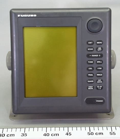
Click to zoom
Application Details
- Equipment Class
- MRD - Marine Radar
- Date of Grant
- May 24, 2005
- Application Purpose
- Original Equipment
- Date of Application
- Jun 28, 2000
- Equipment Note
- MARINE RADAR
- Frequency Range
- 9410.00000000 - 9410.00000000
- Company
- Furuno USA Inc
- Country
- United States
Documents & Files
Document Text
Text extracted from the exhibit documents filed with the FCC. Open a document above to read the original.
Users Manual
MARINE RADAR MODEL 851 MARK-2 C 9-52, Ashihara-cho, Nishinomiya, Japan Telephone: 0798-65-2111 Telefax: 0798-65-4200 Your Local Agent/Dealer All rights reserved. PUB. No. OME-34900 MODEL 851 MARK-2 (TENI) FIRST EDITION: JUNE 2000 Printed in Japan i Do not open the equipment. Hazardous voltage which can cause electrical shock, burn or serious injury exists inside the equipment. Only qualified personnel should work inside the equipment. Wear a safety belt and hard hat when working on the antenna unit. Serious injury or death can result if someone falls from the radar antenna mast. WARNING ELECTRICAL SHOCK HAZARD Stay away from transmitting antenna. The radar antenna emits mi- crowave radiation which can be harmful to the human body, particularly the eyes. Never look directly into the antenna radiator from a distance of less than 1 m when the radar is in operation. Turn off the radar power switch before servicing the antenna unit. Post a warn- ing sign near the switch indicating it should not be turned on while the antenna unit is being serviced. Prevent the potential risk of someone begin struck by the rotating antenna and expo- sure to RF radiation hazard. WARNING Do not disassemble or modify the equipment. Fire, electrical shock or serious injury can result. Turn off the power immediately if water leaks into the equipment or the equipment is emitting smoke or fire. Fire or equipment damage can result if a different cable is used. Keep heater away from equipment. Heat can alter equipment shape and melt the power cord, which can cause fire or electrical shock. CAUTION Use the proper fuse. Use of a wrong fuse can result in fire or permanent equipment damage. A warning label is attatched to the display unit. Do not remove the label. If the label is missing or damaged, contact a FURUNO agent or dealer. SAFETY INSTRUCTIONS WARNING To avoid electrical shock, do not remove cover. No user-serviceable parts inside. Name: Warning Label (2) Type: 03-129-1001-0 Code No.: 100-236-740 ii TABLE OF CONTENTS FOREWORD.......................................... iv SYSTEM CONFIGURATION .................. v 1. PRINCIPLE OF OPERATION 1.1 What is Radar?........................... 1-1 1.2 How Ships Determined Position Before Radar.............................. 1-1 1.3 How Radar Determines Range... 1-1 1.4 How Radar Determines Bearing....................................... 1-1 1.5 Radar Wave Speed and Antenna Rotation Speed .......................... 1-2 1.6 The Radar Display...................... 1-2 2. OPERATION 2.1 Control Description ..................... 2-1 2.2 Display Indications and Markers ...................................... 2-2 2.3 Turning the Radar On and Off .... 2-2 2.4 Transmitting................................ 2-3 2.5 Selecting the Range ................... 2-3 2.6 Adjusting LCD Backlighting and Display Tone............................... 2-3 2.7 Adjusting Control Panel Illumination ................................. 2-4 2.8 Adjusting GAIN, STC, A.C RAIN and FTC ..................................... 2-4 2.9 Tuning the Receiver ................... 2-6 2.10 Measuring the Range ............... 2-6 2.11 Measuring the Bearing ............. 2-7 2.12 Menu Operation........................ 2-8 2.13 Selecting the Display Mode .... 2-10 2.14 The Window Display............... 2-11 2.15 Selecting the Presentation Mode ........................................ 2-12 2.16 Guard Alarm ........................... 2-12 2.17 Suppressing Radar Interference .............................. 2-14 2.18 Suppressing Noise Interference ............................. 2-15 2.19 Selecting Pulselength............. 2-15 2.20 Off Centering the Display ....... 2-15 2.21 Echo Trails ............................. 2-16 2.22 Navigation Data Display......... 2-17 2.23 Echo Stretch (magnifying long range echoes) .................. 2-18 2.24 Selecting Unit of Measurement for Range .......... 2-19 2.25 Selecting Bearing Reference.. 2-19 2.26 Watchman.............................. 2-19 2.27 Erasing the Heading Marker... 2-20 2.28 Deselecting Ranges ............... 2-20 2.29 Displaying Navigation Data During Stand-by....................... 2-20 2.30 Outputting Cursor Position to Navigator ................................. 2-21 2.31 Displaying Cursor Position, Range and Bearing to Cursor .. 2-21 2.32 Visual Alarm Indications ......... 2-21 3. INTERPRETING THE DISPLAY 3.1 The Radar Wave and Radar Horizon ...................................... 3-1 3.2 Target Properties and Radar Wave Reflection......................... 3-2 3.3 Range Resolution ...................... 3-2 3.4 Bearing Resolution..................... 3-2 3.5 False Echoes ............................. 3-3 3.6 SART ......................................... 3-5 3.7 Racon (Radar Beacon) .............. 3-7 4. MAINTENANCE & TROUBLESHOOTING 4.1 Preventative Maintenance.......... 4-1 4.2 Replacing the Fuse .................... 4-2 4.3 Troubleshooting ......................... 4-2 4.4 Test ............................................ 4-3 4.5 Replacing the Magnetron........... 4-3 iii MENU TREE....................................... A-1 SPECIFICATIONS ............................ SP-1 INDEX .......................................... index-1 iv FOREWORD Congratulations on your choice of the FURUNO Marine Radar MODEL 851 MARK-2. We are confident you will see why the FURUNO name has become synonymous with quality and reliability. For over 50 years FURUNO Electric Company has enjoyed an enviable reputation for innovative and dependable marine electronics equipment. This dedication to excellence is furthered by our extensive global network of agents and dealers. Your radar is designed and constructed to meet the rigorous demands of the marine environment. However, no machine can perform its intended function unless properly installed and maintained. Please carefully read and follow the recommended procedures for installation, operation and maintenance. While this unit can be installed by the purch…
Text truncated - open the document above for the full version.
External Photos
LABOTECH Furuno Labotech International Report no.: FLI 12-00-018 - Page E.1 of 18 - Attachment E Photographs of Marine Radar MODEL 851 MARK 2 1 Display unit Photo 1.1 Display Unit Front View LABOTECH Furuno Labotech International Report no.: FLI 12-00-018 - Page E.2 of 18 - Photo 1.2 Display Unit Rear View LABOTECH Furuno Labotech International Report no.: FLI 12-00-018 - Page E.3 of 18 - Photo 1.3 Display Unit Right Side View LABOTECH Furuno Labotech International Report no.: FLI 12-00-018 - Page E.4 of 18 - Photo 1.4 Display Unit Left Side View LABOTECH Furuno Labotech International Report no.: FLI 12-00-018 - Page E.5 of 18 - Photo 1.5 Display Unit Top View
External Photos
LABOTECH Furuno Labotech International Report no.: FLI 12-00-018 - Page E.11 of 18 - 2 Antenna unit Photo 2.1 Radar Antenna Unit Front View LABOTECH Furuno Labotech International Report no.: FLI 12-00-018 - Page E.12 of 18 - Photo 2.2 Radar Antenna Unit Rear View LABOTECH Furuno Labotech International Report no.: FLI 12-00-018 - Page E.13 of 18 - Photo 2.3 Radar Antenna Unit Inside View (Showing Scanner Motor and Transceiver Module) LABOTECH Furuno Labotech International Report no.: FLI 12-00-018 - Page E.14 of 18 - Photo 2.4 Transceiver Module Top View (Showing MIC, Circulator and Magnetron) LABOTECH Furuno Labotech International Report no.: FLI 12-00-018 - Page E.15 of 18 - Fig. 2.5 Transceiver Module Bottom View
External Photos
LABOTECH Furuno Labotech International Report no.: FLI 12-00-018 - Page E.16 of 18 - LABOTECH Furuno Labotech International Report no.: FLI 12-00-018 - Page E.17 of 18 - Fig. 2.7 IF Board 03P9215 (left) and TB & Motor Starter Board 03P9249 (right) LABOTECH Furuno Labotech International Report no.: FLI 12-00-018 - Page E.18 of 18 - 3 Name plates Photo 3.1 Name plate for Display unit Photo 3.2 Name plate for Antenna unit
External Photos
LABOTECH Furuno Labotech International Co., Ltd. Document number: FLI 01-00-018 Date of issue: August 11, 2000 - Page 1 of 16 - Photographs of the printed circuit boards for RADAR MODEL 851 MARK 2 1 Display Unit RDP-1171.1 SPU Board SPU-9180(a) Parts (Top) side: LABOTECH Furuno Labotech International Co., Ltd. Document number: FLI 01-00-018 Date of issue: August 11, 2000 - Page 2 of 16 - (b) Soldered (Bottom) side: LABOTECH Furuno Labotech International Co., Ltd. Document number: FLI 01-00-018 Date of issue: August 11, 2000 - Page 3 of 16 - 1.2 INT Board INT9216(a) Parts (Top) side: LABOTECH Furuno Labotech International Co., Ltd. Document number: FLI 01-00-018 Date of issue: August 11, 2000 - Page 4 of 16 - (b) Soldered (Bottom) side:
External Photos
LABOTECH Furuno Labotech International Co., Ltd. Document number: FLI 01-00-018 Date of issue: August 11, 2000 - Page 5 of 16 - 1.3 Power Supply Boards PTU9202 & PTA92031.3.1 PTU9202(a) Parts (Top) side: LABOTECH Furuno Labotech International Co., Ltd. Document number: FLI 01-00-018 Date of issue: August 11, 2000 - Page 6 of 16 - (b) Soldered (Bottom) side: LABOTECH Furuno Labotech International Co., Ltd. Document number: FLI 01-00-018 Date of issue: August 11, 2000 - Page 7 of 16 - 1.3.2 PTA9203(a) Parts (Top) side: LABOTECH Furuno Labotech International Co., Ltd. Document number: FLI 01-00-018 Date of issue: August 11, 2000 - Page 8 of 16 - (b) Soldered (Bottom) side: LABOTECH Furuno Labotech International Co., Ltd. Document number: FLI 01-00-018 Date of issue: August 11, 2000 - Page 9 of 16 - 1.4 PNL Board PNL9177(a) Parts (Top) side: LABOTECH Furuno Labotech International Co., Ltd. Document number: FLI 01-00-018 Date of issue: August 11, 2000 - Page 10 of 16 - (b) Soldered (Bottom) side:
ID Label/Location Info
LABOTECH This report shall not be reproduced except in full, without the written approval of Furuno Labotech International Co., Ltd. TECHNICAL INFORMATION TEST REPORT ON THE PERFORMANCE OF MARINE RADAR Trade Mark : FURUNO Model : MODEL 851 MARK 2 Report no.: FLI 12-00-018 Date of issue: 16 June 2000 Furuno Labotech International Co., Ltd. 9-52 Ashihara-cho, Nishinomiya City, Hyogo 662-8580, Japan Tel: +81-798-63-1094 Fax: +81-798-63-1098 LABOTECH Furuno Labotech International Report no.: FLI 12-00-018 - Page 1 of 38 - All tests were performed in Furuno Labotech International Co., Ltd. All data herein contained is true and correct to our best knowledge. All tests were performed by: Name: Katsumi Imamura Function: Test Engineer Signature: Review and report by: Name: Toshiro Segawa Function: Manager, QA Signature: This report has been verified and approved by: Date: 16 June 2000 Name: Mitsuyoshi Komori Function: Manager, Technical Section Signature: LABOTECH Furuno Labotech International Report no.: FLI 12-00-018 - Page 2 of 38 - * * * * * * C O N T E N T S * * * * * * 1General Information.........................................................................................................................3 2Identification of Equipment (FCC Rule §2.925).............................................................................9 3Test data..........................................................................................................................................10 3.1RF Power Output (FCC Rule §2.1046)............................................................................................10 3.2 Modulation Characteristics (FCC Rule §2.1047)............................................................................13 3.3Occupied Bandwidth (FCC Rule §2.1049).......................................................................................18 3.4Spurious Emissions at Antenna Terminal (FCC Rule §2.1051).......................................................20 3.5Field Strength of Spurious Radiation (FCC Rule §2.1053)...........................................................23 3.6Frequency Stability (FCC Rule §2.1055)..........................................................................................25 3.7Suppression of Interference Aboard Ships (FCC Rule § 80.217)....................................................28 4Photographs to Reveal Equipment Construction and Layout (FCC Rule §2.1033)..........32 5Description of Circuitry and Devices (FCC Rules §2.1033).....................................................33 5.1 Function of Each Semiconductor or Active Device...........................................................................33 5.2 Description of the circuits employed for suppression of spurious radiation, for limiting or shaping the control pulse, and for limiting or controlling power...........................................................................35 6 Operator’s Manual Incl. Circuit Diagrams (FCC Rule §2.1033).......................................................38 Attachment A[ Test data for 3.4 Spurious Emissions at Antenna Terminal ] ......... A.1 - A.6 Attachment B[ Test data for 3.5 Field Strength of Spurious Radiation ] ......... B.1 - B.3 Attachment C[ Test data for 3.7 Suppression of Interference Aboard Ships ] ......... C.1 - C.21 Attachment D[ List of Test/Measuring Equipment ] ......... D.1 - D.3 Attachment E[ Photographs of the EUT ] ......... E.1 - E.18 LABOTECH Furuno Labotech International Report no.: FLI 12-00-018 - Page 3 of 38 - 1General Information 1.1General (a)Manufacturer:Furuno Electric Co., Ltd. Ashihara-cho 9-52, Nishinomiya-city, 662-8580 Japan (b)Model:MODEL 851 MARK 2 Serial no.:4302-0002 (c)Primary Function:Search, Navigation and anticollison (d)Discrimination Range Discrimination:20 meters on a range scale of 0.25 nm Bearing Discrimination:2.4on a range scale of 1.5 nm (e)Minimum Range:25 meters on a range scale of 0.25 nm (f)Frequency Range:Fixed frequency, X-band Type of Emission:P0N (g)Power Supply: 12 - 24 VDC 1.2Antenna Unit 1.2.1Transceiver Type:RTR-065 (1)Transmitter (a)Assignable Frequency for Shipborne Radar: Between 9300 and 9500 MHz (FCC Rule 80.375 (d)-(1)) (b)Type of RF Generator Magnetron Type:MG5248 E3571E3571A Peak Output Power:4 kW nominal (c)Magnetron Ratings Center frequency of Magnetron:9410 MHz Tolerances MG5248E3571E3571A Manufacturing:30 MHz30 MHz30 MHz Pulling:23 MHz27 MHz27 MHz Tolerance for 20C temperature variation: 5 MHz (d) Guard Band: Guard Band is specified to be equal to 1.5/T MHz, where "T" is the pulselength in microseconds. See para (e). (FCC Rule 80.209(b)) LABOTECH Furuno Labotech International Report no.: FLI 12-00-018 - Page 4 of 38 - (e) Pulse Characteristics: Range Scale (nm)(Short ) 0.125 0.25 0.5 0.75 1 1.5 (Middle) 1.5 2 3 (Long ) 3 4 6 8 12 16 24 48 Pulselength (μs) 0.080.300.80 P.R.R.(Hz)21001200600 Duty cycle1.68X10 -4 3.60X10 -4 4.80X10 -4 Guard Band (MHz)18.755.001.88 Note 1: Tests were carried out for the underlined Range Scales. (2)Modulator (a)FET Type:2SK1450 Trigger Voltage: Approx. +10 VDC positive (3)Receiver (a)Passband (MHz) RF Stage:100 MHz IF Stage: PulselengthShortMiddleLong (MHz)777 LABOTECH Furuno Labotech International Report no.: FLI 12-00-018 - Page 5 of 38 - Video Amp.: PulselengthShortMiddleLong (MHz)14143 (b)Gain (overall) (dB):Sufficient to cause limiting, approximately 130 (c)Overall Noise Figure (dB): 6 (typical) (d)Video Output Voltage (V): 3.8 V positive (e)Features Provided: Sensitivity Time Controls (Anti-clutter Sea), Fast Time Constant (Anti-clutter Rain) (f)If receiver is tunable, describe method of adjusting frequency: Adjustment of tuning voltage of receiver local oscillator (Automatic and manual) 1.2.2Antenna (a)Antenna Rotation ON-OFF Switch: Not Provided. (b) Reflector:Slotted waveguide antenna Radiator typeXN8 Length (cm)100 (c)Type of Beam:Vertical fan (d)Beam Width (between half-Radiator power points) Horizontal 2.4 Vertical…
Text truncated - open the document above for the full version.
Internal Photos
LABOTECH Furuno Labotech International Co., Ltd. Document number: FLI 01-00-018 Date of issue: August 11, 2000 - Page 11 of 16 - 2 Antenna Unit 2.1 MD Board 03P9235 (a) Parts (Top) side: LABOTECH Furuno Labotech International Co., Ltd. Document number: FLI 01-00-018 Date of issue: August 11, 2000 - Page 12 of 16 - (b) Soldered (Bottom) side: LABOTECH Furuno Labotech International Co., Ltd. Document number: FLI 01-00-018 Date of issue: August 11, 2000 - Page 13 of 16 - 2.2 TB & Motor Starter Board 03P9249 (a) Parts (Top) side: LABOTECH Furuno Labotech International Co., Ltd. Document number: FLI 01-00-018 Date of issue: August 11, 2000 - Page 14 of 16 - (b) Soldered (Bottom) side: LABOTECH Furuno Labotech International Co., Ltd. Document number: FLI 01-00-018 Date of issue: August 11, 2000 - Page 15 of 16 - 2.3 IF Board 03P9215(a) Parts (Top) side: LABOTECH Furuno Labotech International Co., Ltd. Document number: FLI 01-00-018 Date of issue: August 11, 2000 - Page 16 of 16 - (b) Soldered (Bottom) side:
Test Report
LABOTECH Furuno Labotech International Report no. : FLI 12-00-018 Attachment A [ TEST DATA for Clause 3.4. SPURIOUS EMISSIONS AT ANTENNA TERMINALS ] 1. Spurious emissions for 0.125 nm Range: Ref. level: -3.65 dBm Emission limitations: (a)25 dB for 50 to 100 % of the authorized BW (100 MHz) (b)35 dB for 100 to 250 % of the authorized BW (100 MHz) Fig. 1.1 Without Filter Emission limitations: (c) 43 + 10 log Pm = 41.9 dB for more than 250 % of the authorized BW (100 MHz) Fig. 1.2 Without Filter Emission limitations: (c) 43 + 10 log Pm = 41.9 dB for more than 250 % of the authorized BW (100 MHz) Fig. 1.3 With Filter No. 2 - Page A1 of 6 - LABOTECH Furuno Labotech International Report no. : FLI 12-00-018 Emission limitations: (c) 43 + 10 log Pm = 41.9 dB for more than 250 % of the authorized BW (100 MHz) Fig. 1.4 With Filter No. 2 Emission limitations: (c) 43 + 10 log Pm = 41.9 dB for more than 250 % of the authorized BW (100 MHz) Fig. 1.5 With Filter No. 2 - Page A2 of 6 - LABOTECH Furuno Labotech International Report no. : FLI 12-00-018 2.Spurious emissions for 3 nm Range: Ref. level: 4.69 dBm Emission limitations: (a)25 dB for 50 to 100 % of the authorized BW (100 MHz) (b)35 dB for 100 to 250 % of the authorized BW (100 MHz) Fig. 2.1 Without Filter Emission limitations: (c) 43 + 10 log Pm = 43.92 dB for more than 250 % of the authorized BW (100 MHz) Fig. 2.2 Without Filter Emission limitations: (c) 43 + 10 log Pm = 43.92 dB for more than 250 % of the authorized BW (100 MHz) Fig. 2.3 With Filter No. 2 - Page A3 of 6 - LABOTECH Furuno Labotech International Report no. : FLI 12-00-018 Emission limitations: (c) 43 + 10 log Pm = 43.92 dB for more than 250 % of the authorized BW (100 MHz) Fig. 2.4 With Filter No. 2 Emission limitations: (c) 43 + 10 log Pm = 43.92 dB for more than 250 % of the authorized BW (100 MHz) Fig. 2.5 With Filter No. 2 - Page A4 of 6 - LABOTECH Furuno Labotech International Report no. : FLI 12-00-018 3.Spurious emissions for 48 nm Range: Ref. level: 11.7 dBm Emission limitations: (a)25 dB for 50 to 100 % of the authorized BW (100 MHz) (b)35 dB for 100 to 250 % of the authorized BW (100 MHz) Fig. 3.1 Without Filter Emission limitations: (c) 43 + 10 log Pm = 45.32 dB for more than 250 % of the authorized BW (100 MHz) Fig. 3.2 Without Filter Emission limitations: (c) 43 + 10 log Pm = 45.32 dB for more than 250 % of the authorized BW (100 MHz) Fig. 3.3 With Filter No. 2 - Page A5 of 6 - LABOTECH Furuno Labotech International Report no. : FLI 12-00-018 Emission limitations: (c) 43 + 10 log Pm = 45.32 dB for more than 250 % of the authorized BW (100 MHz) Fig. 3.4 With Filter No. 2 Emission limitations: (c) 43 + 10 log Pm = 45.32 dB for more than 250 % of the authorized BW (100 MHz) Fig. 3.5 With Filter No. 2 - Page A6 of 6 -
Test Report
LABOTECH Furuno Labotech International Report no. : FLI 12-00-018 Attachment B - Page B.1 of 3 - LABOTECH Furuno Labotech International Report no. : FLI 12-00-018 - Page B.2 of 3 - LABOTECH Furuno Labotech International Report no. : FLI 12-00-018 - Page B.3 of 3 -
Test Report
LABOTECH Furuno Labotech International Report no. : FLI 12-00-018 Attachment C [ TEST DATA for Clause 3.7 SUPPRESSION OF INTERFERENCE ABOARD SHIPS ] 1.Harmful Interference to Receiver (Band : 14 kHz - 490 kHz) - Page C.1 of 21 - LABOTECH Furuno Labotech International Report no. : FLI 12-00-018 . (Band : 490 kHz - 5 MHz) - Page C.2 of 21 - LABOTECH Furuno Labotech International Report no. : FLI 12-00-018 (Band : 5 MHz - 10 MHz) - Page C.3 of 21 - LABOTECH Furuno Labotech International Report no. : FLI 12-00-018 (Band : 10 MHz - 30 MHz) - Page C.4 of 21 - LABOTECH Furuno Labotech International Report no. : FLI 12-00-018 (Band : 30 MHz - 100 MHz) - Page C.5 of 21 - LABOTECH Furuno Labotech International Report no. : FLI 12-00-018 (Band : 100 MHz - 300 MHz) - Page C.6 of 21 - LABOTECH Furuno Labotech International Report no. : FLI 12-00-018 (Band : 300 MHz - 1 GHz) - Page C.7 of 21 - LABOTECH Furuno Labotech International Report no. : FLI 12-00-018 2.Electromagnetic Field (Band : 14 kHz - 490 kHz, Limit at 1 nm = 0.1 μV/m = -20 dBμV/m) -26 dBμV/m -26 dBμV/m - Page C.8 of 21 - LABOTECH Furuno Labotech International Report no. : FLI 12-00-018 (Band : 490 kHz - 5 MHz, Limit at 1 nm = 0.1 μV/m = -20 dBμV/m) Ref. level (dBμV/m) = 100 - 126 = -26 (at 0.5 MHz) = 100 - 96 = 4 (at 3 MHz) = 100 - 88 = 12 (at 5 MHz) -20 dBμV/m limit line - Page C.9 of 21 - LABOTECH Furuno Labotech International Report no. : FLI 12-00-018 (Band : 5 MHz - 10 MHz, Limit at 1 nm = 0.1 μV/m = -20 dBμV/m) Ref. level (dBμV/m) = 100 - 88 = 12 (at 5 MHz) = 100 - 83 = 17 (at 7 MHz) = 100 - 78 = 22 (at 10 MHz) -20 dBμV/m limit line - Page C.10 of 21 - LABOTECH Furuno Labotech International Report no. : FLI 12-00-018 (Band : 10 MHz - 30 MHz, Limit at 1 nm = 0.1 μV/m = -20 dBμV/m) Ref. level (dBμV/m) = 100 - 78 = 22 (at 10 MHz) = 100 - 70 = 30 (at 20 MHz) = 100 - 67 = 33 (at 30 MHz) -20 dBμV/m limit line - Page C.11 of 21 - LABOTECH Furuno Labotech International Report no. : FLI 12-00-018 (Band : 30 MHz - 100 MHz, Limit at 1 nm = 0.1 μV/m = -10.5 dBμV/m) Ref. level (dBμV/m) = 100 - 61 = 39 - 10.5 dBμV/m limit line All components above the limit are from external noise or signals, not from RADAR. - Page C.12 of 21 - LABOTECH Furuno Labotech International Report no. : FLI 12-00-018 (Band : 100 MHz - 300 MHz, Limit at 1 nm = 0.1 μV/m = -0 dBμV/m) Ref. level (dBμV/m) = 100 - 60 = 40 0 dBμV/m limit line All components above the limit are from external noise or signals, not from RADAR. - Page C.13 of 21 - LABOTECH Furuno Labotech International Report no. : FLI 12-00-018 (Band : 300 MHz - 1 GHz, Limit at 1 nm = 3 μV/m = -9.5 dBμV/m) Ref. level (dBμV/m) = 100 - 59.5 = 40.5 9.5 dBμV/m limit line - Page C.14 of 21 - LABOTECH Furuno Labotech International Report no. : FLI 12-00-018 3.Power Input to an Artificial Antenna (Band : 14 kHz - 490 kHz, Limit at 2 m = -81 dBm) -81 dBm limit line All components above the limit are from external noise or signals, not from RADAR. - Page C.15 of 21 - LABOTECH Furuno Labotech International Report no. : FLI 12-00-018 (Band : 490 kHz - 5 MHz, Limit at 2 m = -81 dBm) -81 dBm limit line All components above the limit are from external noise or signals, not from RADAR. - Page C.16 of 21 - LABOTECH Furuno Labotech International Report no. : FLI 12-00-018 (Band : 5 MHz - 10 MHz, Limit at 2 m = -81 dBm) -81 dBm limit line All components above the limit are from external noise or signals, not from RADAR. - Page C.17 of 21 - LABOTECH Furuno Labotech International Report no. : FLI 12-00-018 (Band : 10 MHz - 30 MHz, Limit at 2 m = -81 dBm) All components above the limit are from external noise or signals, not from RADAR. -81 dBm limit line - Page C.18 of 21 - LABOTECH Furuno Labotech International Report no. : FLI 12-00-018 (Band : 30 MHz - 100 MHz, Limit at 2 m = -71 dBm) -71 dBm limit line All components above the limit are from external noise or signals, not from RADAR. - Page C.19 of 21 - LABOTECH Furuno Labotech International Report no. : FLI 12-00-018 (Band : 100 MHz - 300 MHz, Limit at 2 m = -61 dBm) -61 dBm limit line All components above the limit are from external noise or signals, not from RADAR. - Page C.20 of 21 - LABOTECH Furuno Labotech International Report no. : FLI 12-00-018 (Band : 300 MHz - 1 GHz, Limit at 2 m = -51 dBm) -51 dBm limit line - Page C.21 of 21 -
Test Report
LABOTECHFuruno Labotech International Report no.: FLI 12-00-018 - Page D.1 of 3 - Attachment D [ List of Test/Measuring Equipment ] (for X-band radar) For Clause 3.1 RF Power Output ModelTypeSerial no.Mfr. Spectrum Analyzer71210C2927A02847HP OscilloscopeTDS680BB030202Tektronix Directional Coupler5D364SR05762Shimada Voltage DividerHV-P302780Iwatsu Current Transformer2100----Pearson Electronics Power Meter436A2410A19137HP Power Sensor8481A2349A39603HP Frequency CounterTR5824A41940036Advantest Frequency MeterX532B1441A00523HP Crystal Detector423A1822A09909HP Step Attenuator8494B1510A07310HP Step Attenuator8495B1350A04754HP Dummy Load4D376R05763Shimada For Clause 3.2 Modulation Characteristics ModelTypeSerial no.Mfr. OscilloscopeTDS680BB030202Tektronix Step Attenuator8494B1510A07310HP Step Attenuator8495B1350A04754HP Crystal Detector423A1822A09909HP Directional Coupler5D364SR05762Shimada Dummy Load4D376R05763Shimada Voltage DividerHV-P302780Iwatsu Spectrum Analyzer71210C2927A02847HP LABOTECHFuruno Labotech International Report no.: FLI 12-00-018 - Page D.2 of 3 - For Clause 3.4 Spurious Emissions at Antenna Terminal ModelTypeSerial no.Mfr. Spectrum Analyzer71210C2927A02847HP Attenuator (10 dB)8491B28845HP External Mixer:11970K2332A00589HP External Mixer:11970A2332A01187HP Directional Coupler5D364SR05762Shimada Dummy Load4D376R05763Shimada High Pass Filter----------Furuno For Clause 3.5 Field Strength of Spurious Radiation ModelTypeSerial no.Mfr. Broadband Rod Antenna95010-1Advanced Electronics Biconical AntennaBIA-252650Electro Metrics Conical Log-Spiral AntennaLCA-252886Electro Metrics Double Ridged Guide Horn Antenna :RGA-180 2248Electro Metrics Horn Antenna:--------Toshiba Spectrum Analyzer:71210C2927A02847HP External Mixer:11970K2332A00589HP External Mixer:11970A2332A01187HP Attenuator (10 dB)8491B28845HP Attenuator (20 dB)8491A40072HP LABOTECHFuruno Labotech International Report no.: FLI 12-00-018 - Page D.3 of 3 - For Clause 3.6 Frequency Stability ModelTypeSerial no.Mfr. Power Meter:436A2410A19137HP Power Sensor:8481A2349A39603HP Frequency Meter:X532B1441A00523HP Directional Coupler:5D364SR5762Shimada Dummy Load:4D376R05763Shimada Environmental Chamber:PL-4KP14004204Tabai Espec For Clause 3.7 Suppression of Interference Aboard Ships ModelTypeSerial no.Mfr. Spectrum Analyzer:71210C2927A02847HP 6 m Whip Antenna 14 k - 10 MHz ----Furuno 4 m Whip Antenna 10 - 30 MHz ----Furuno VHF Whip Antenna 30 - 300 MHz 150M-W2UMAnten UHF Whip Antenna300 - 1000 MHz----Anten RF Vector Impedance Meter: 4815A2048A03354HP Spectrum AnalyzerTR417230690116Advantest Spectrum Analyzer8566B2637A03642HP Attenuator (10 dB)8491A36122HP
Test Report
LABOTECH This report shall not be reproduced except in full, without the written approval of Furuno Labotech International Co., Ltd. TECHNICAL INFORMATION TEST REPORT ON THE PERFORMANCE OF MARINE RADAR Trade Mark : FURUNO Model : MODEL 851 MARK 2 Report no.: FLI 12-00-018 Date of issue: 16 June 2000 Furuno Labotech International Co., Ltd. 9-52 Ashihara-cho, Nishinomiya City, Hyogo 662-8580, Japan Tel: +81-798-63-1094 Fax: +81-798-63-1098 LABOTECH Furuno Labotech International Report no.: FLI 12-00-018 - Page 1 of 38 - All tests were performed in Furuno Labotech International Co., Ltd. All data herein contained is true and correct to our best knowledge. All tests were performed by: Name: Katsumi Imamura Function: Test Engineer Signature: Review and report by: Name: Toshiro Segawa Function: Manager, QA Signature: This report has been verified and approved by: Date: 16 June 2000 Name: Mitsuyoshi Komori Function: Manager, Technical Section Signature: LABOTECH Furuno Labotech International Report no.: FLI 12-00-018 - Page 2 of 38 - * * * * * * C O N T E N T S * * * * * * 1General Information.........................................................................................................................3 2Identification of Equipment (FCC Rule §2.925).............................................................................9 3Test data..........................................................................................................................................10 3.1RF Power Output (FCC Rule §2.1046)............................................................................................10 3.2 Modulation Characteristics (FCC Rule §2.1047)............................................................................13 3.3Occupied Bandwidth (FCC Rule §2.1049).......................................................................................18 3.4Spurious Emissions at Antenna Terminal (FCC Rule §2.1051).......................................................20 3.5Field Strength of Spurious Radiation (FCC Rule §2.1053)...........................................................23 3.6Frequency Stability (FCC Rule §2.1055)..........................................................................................25 3.7Suppression of Interference Aboard Ships (FCC Rule § 80.217)....................................................28 4Photographs to Reveal Equipment Construction and Layout (FCC Rule §2.1033)..........32 5Description of Circuitry and Devices (FCC Rules §2.1033).....................................................33 5.1 Function of Each Semiconductor or Active Device...........................................................................33 5.2 Description of the circuits employed for suppression of spurious radiation, for limiting or shaping the control pulse, and for limiting or controlling power...........................................................................35 6 Operator’s Manual Incl. Circuit Diagrams (FCC Rule §2.1033).......................................................38 Attachment A[ Test data for 3.4 Spurious Emissions at Antenna Terminal ] ......... A.1 - A.6 Attachment B[ Test data for 3.5 Field Strength of Spurious Radiation ] ......... B.1 - B.3 Attachment C[ Test data for 3.7 Suppression of Interference Aboard Ships ] ......... C.1 - C.21 Attachment D[ List of Test/Measuring E…
Text truncated - open the document above for the full version.
Contact Information
Applicant
Bill Haynes(Deep Sea Product Manager)
Technical Contact
FURUNO U.S.A., INC.CHARLES ZANARDI
[email protected](888) 834-9330
4400 N.W. PACIFIC RIM BLVD · CAMAS, Washington · United States
Non-Technical Contact
FURUNO U.S.A., INC.CHARLES ZANARDI
[email protected](888) 834-9330
Test Firm
Labotech International Co., LtdYoshihiro Ishii
Technical Specifications
| # | Rule Parts | Frequency Range | Power Output | Emission | Tolerance |
|---|---|---|---|---|---|
| 1 | 80,90 | 9.41 GHz - 9.41 GHz | 4000 W | 47M5PON | 0.3190000000 % |
Other Applications from Furuno USA Inc
ADB-9ZWRTR137
Feb 18, 2026Transceiver unit for the radar sensor
Equipment Class
MRD - Marine RadarADB9ZWRTR136
Jul 01, 2024Transceiver unit for the radar sensor
Equipment Class
MRD - Marine Radar
ADB9ZWRTR128
Apr 06, 2022Transceiver unit for the radar sensor
Equipment Class
MRD - Marine Radar
ADB9ZWRTR133
Sep 26, 2021Transceiver unit for the radar sensor
Equipment Class
MRD - Marine Radar
ADB9ZWRTR129
May 23, 2021Transceiver unit for the radar sensor
Equipment Class
MRD - Marine Radar