ADB9ZWRTR074Marine Radar
Furuno USA Inc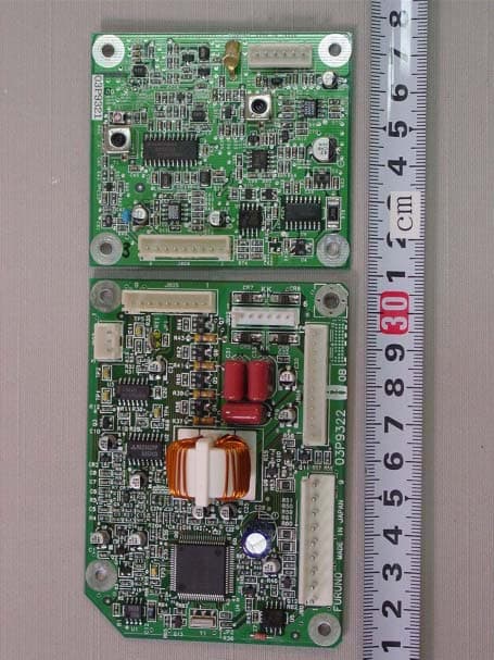
Click to zoom
Application Details
- Equipment Class
- MRD - Marine Radar
- Date of Grant
- May 04, 2005
- Application Purpose
- Original Equipment
- Date of Application
- May 21, 2002
- Equipment Note
- Marine Radar
- Frequency Range
- 9300.00000000 - 9500.00000000
- Company
- Furuno USA Inc
- Country
- United States
Documents & Files
Document Text
Text extracted from the exhibit documents filed with the FCC. Open a document above to read the original.
ID Label/Location Info
LL LL AA AA BB BB OO OO TT TT EE EE CC CC HH HH Furuno Labotech International Report no.: FLI 12-02-016 Form: Q053/01 - Page 9 of 37 - 2Identification of Equipment (FCC Rule §§ §§ 2.925) The following nameplates are permanently fixed on the corresponding equipment units. FCC ID: ADB9ZWRTR074 Material of nameplate: Polyester film, 0.1 mm thick Fig. 2.1 Nameplate for Antenna Unit Fig. 2.2 Nameplate for Display Unit MARINE RADAR TYPE SER. NO. ANTENNA UNIT FURUNO ELECTRIC CO., LTD. 9-5 2 A shihara-Cho, Nishinomiya Cit y, Japan MADE IN JAPAN COMPASS SAFE DISTANCE M STEER M STD FCC ID: ADB9ZWRTR074 FURUNO USA, INC. MODEL TYPE INPUT SER. NO. DISPLAY UNIT COMPASS SAFE DISTANCE STD MM NISHINOMIYA CITY. MADE IN JAPAN FURUNO ELECTRIC CO., LTD. STEER MARINE RADAR RSB-0093 R127- 1623 RDP-141 12 - 24 VDC 4311-
ID Label/Location Info
LL LL AA AA BB BB OO OO TT TT EE EE CC CC HH HH Furuno Labotech International Report no.: FLI 12-02-016 - Page E.8 of 18 - 1.8 Name Plate
Internal Photos
LL LL AA AA BB BB OO OO TT TT EE EE CC CC HH HH Furuno Labotech International Report no.: FLI 12-02-016 - Page E.1 of 18 - Attachment E Photographs of the EUT MODEL 1623 (Transceiver RTR-074) 1 Antenna Unit RSB-0093 (including Transceiver RTR-074) 1.1 Outside View LL LL AA AA BB BB OO OO TT TT EE EE CC CC HH HH Furuno Labotech International Report no.: FLI 12-02-016 - Page E.2 of 18 - 1.2 Inside View (showing Antenna Radiator and Transceiver Module (RTR-074)) LL LL AA AA BB BB OO OO TT TT EE EE CC CC HH HH Furuno Labotech International Report no.: FLI 12-02-016 - Page E.3 of 18 - 1.3 Inside View (with shield-covers removed, showing Magnetron (upper left), MIC (lower left), MD Board 03P9270 (upper right), Scanner Motor (center right) and INT Board 03P9322 (lower right)) LL LL AA AA BB BB OO OO TT TT EE EE CC CC HH HH Furuno Labotech International Report no.: FLI 12-02-016 - Page E.4 of 18 - 1.4 MD Board 03P9270 Front side LL LL AA AA BB BB OO OO TT TT EE EE CC CC HH HH Furuno Labotech International Report no.: FLI 12-02-016 - Page E.5 of 18 - 1.5 MD Board 03P9270 Rear side LL LL AA AA BB BB OO OO TT TT EE EE CC CC HH HH Furuno Labotech International Report no.: FLI 12-02-016 - Page E.6 of 18 - 1.6 IF 03P9321 (upper) and INT 03P9322 (lower) Boards Front side LL LL AA AA BB BB OO OO TT TT EE EE CC CC HH HH Furuno Labotech International Report no.: FLI 12-02-016 - Page E.7 of 18 - 1.7 IF 03P9321 (upper) and INT 03P9322 (lower) Boards Rear side LL LL AA AA BB BB OO OO TT TT EE EE CC CC HH HH Furuno Labotech International Report no.: FLI 12-02-016 - Page E.8 of 18 - 1.8 Name Plate LL LL AA AA BB BB OO OO TT TT EE EE CC CC HH HH Furuno Labotech International Report no.: FLI 12-02-016 - Page E.9 of 18 - 2 Display Unit RDP-141 2.1 Front View LL LL AA AA BB BB OO OO TT TT EE EE CC CC HH HH Furuno Labotech International Report no.: FLI 12-02-016 - Page E.10 of 18 - 2.2 Rear View (showing Name Plate and Warning Label) LL LL AA AA BB BB OO OO TT TT EE EE CC CC HH HH Furuno Labotech International Report no.: FLI 12-02-016 - Page E.11 of 18 - 2.3 Inside View (showing DU Board 03P9320) LL LL AA AA BB BB OO OO TT TT EE EE CC CC HH HH Furuno Labotech International Report no.: FLI 12-02-016 - Page E.12 of 18 - 2.4 DU Board 03P9320 Rear side LL LL AA AA BB BB OO OO TT TT EE EE CC CC HH HH Furuno Labotech International Report no.: FLI 12-02-016 - Page E.13 of 18 - 2.5 Inside View (with DU Board removed) LL LL AA AA BB BB OO OO TT TT EE EE CC CC HH HH Furuno Labotech International Report no.: FLI 12-02-016 - Page E.14 of 18 - 2.6 Inside View (showing LCD Module) LL LL AA AA BB BB OO OO TT TT EE EE CC CC HH HH Furuno Labotech International Report no.: FLI 12-02-016 - Page E.15 of 18 - 2.7 LCD Module Rear side LL LL AA AA BB BB OO OO TT TT EE EE CC CC HH HH Furuno Labotech International Report no.: FLI 12-02-016 - Page E.16 of 18 - 2.8 Inside View (showing Back of Front Panel and PNL Board 02P6305) LL LL AA AA BB BB OO OO TT TT EE EE CC CC HH HH Furuno Labotech International Report no.: FLI 12-02-016 - Page E.17 of 18 - 2.9 PNL Board 02P6305 Front side LL LL AA AA BB BB OO OO TT TT EE EE CC CC HH HH Furuno Labotech International Report no.: FLI 12-02-016 - Page E.18 of 18 - 2.10 Inside View (Back of Front Panel with PNL Board removed)
Operational Description
MARINE RADAR MODEL 1623 Your Local Agent/DealerYour Local Agent/Dealer 9-52 Ashihara-cho,9-52 Ashihara-cho, Nishinomiya, JapanNishinomiya, Japan Telephone :Telephone :0798-65-21110798-65-2111 Telefax :Telefax :0798-65-42000798-65-4200 FIRST EDITION :FIRST EDITION : . .00000000 Printed in JapanPrinted in Japan All rights reserved.All rights reserved. PUB.No.PUB.No.OME-35100OME-35100 (()) MODEL1623MODEL1623 *OME35100Z00**OME35100Z00* *OME35100Z00**OME35100Z00* * O M E 3 5 1 0 0 Z 0 0 ** O M E 3 5 1 0 0 Z 0 0 * i SAFETY INSTRUCTIONS WARNING ELECTRICAL SHOCK HAZARD Do not open the equipment. Only qualified personnel should work inside the equipment. Turn off the radar power switch before servicing the antenna unit. Post a warning sign near the switch indi- cating that it should not be turned on while the antenna unit is being serviced. Prevent the potential risk of being struck by the rotating antenna and exposure to RF radiation hazard. Wear a safety belt and hard hat when working on the antenna unit. Serious injury or death can result if someone falls from the radar antenna mast. Do not disassemble or modify the equipment. Fire, electrical shock or serious injury can result. Turn off the power immediately if water leaks into the equipment or the equip- ment is emitting smoke or fire. Continued use of the equipment can cause fire or electrical shock. WARNING Use the proper fuse. Use of a wrong fuse can damage the equipment and void the warranty. Keep heater away from equipment. Heat can alter equipment shape and melt the power cord, which can cause fire or electrical shock. NOTICE A warning label is attached to the equipment. Do not remove the label. If the label is missing or damaged, contact a FURUNO agent or dealer. WARNING To avoid electrical shock, do not remove cover. No user-serviceable parts inside. Name: Warning Label (1) Type: 86-003-1011-0 Code No.: 100-236-230 Safety Instructions for the Operator ii Safety Instructions for the Installer Ground the equipment to prevent mutual interference. NOTICE Observe the following compass safe distances to prevent interference to a magnetic compass: Standard Steering compass compass TBA TBA Antenna unit TBA TBA Display unit Do not open the equipment unless totally familiar with electrical circuits and service manual. Only qualified personnel should work inside the equipment. Wear a safety belt and hard hat when working on the antenna unit. Serious injury or death can result if someone falls from the radar antenna mast. WARNING Construct a suitable service platform from which to install the antenna unit. Serious injury or death can result if some- one falls from the radar antenna mast. Be sure that the power supply is compatible with the voltage rating of the equipment. Connection of an incorrect power supply can cause fire or damage the equipment. Use only the specified power cable. Fire or equipment damage can result if a different cable is used. ELECTRICAL SHOCK HAZARD iii TABLE OF CONTENTS FOREWORD ............................................ iv SYSTEM CONFIGURATION ..................... v EQUIPMENT LISTS ................................. vi 1. OPERATION ........................................ 1 1.1 Controls ............................................... 1 1.2 Indications ........................................... 2 1.3 Turning Power On/Off.......................... 3 1.4 Transmitting, Standby .......................... 3 1.5 Adjusting Display Contrast, Brilliance.. 3 1.6 Choosing the Range............................ 4 1.7 Receiver Sensitivity ............................. 4 1.8 Suppressing Sea Clutter...................... 5 1.9 Suppressing Rain Clutter..................... 6 1.10 Measuring the Range .......................... 6 1.11 Measuring the Bearing ........................ 7 1.12 Shifting the Display.............................. 7 1.13 Zoom.................................................... 8 1.14 User Menu Overview ........................... 8 1.15 Heading Line ....................................... 9 1.16 Interference Rejector ........................... 9 1.17 Noise Rejector ..................................... 9 1.18 Echo Trail, Trail Brilliance .................... 9 1.19 Echo Stretch ...................................... 10 1.20 Guard Alarm ...................................... 10 1.21 Watchman.......................................... 11 1.22 Suppressing Long-range Rain Clutter ................................................. 11 1.23 Panel Backlighting ............................. 12 1.24 Hue .................................................... 12 1.25 Resetting Distance Run..................... 12 1.26 PROG Key ......................................... 12 1.27 Turning Navigation Data On/Off ........ 13 1.28 Outputting Cursor Position to Navigator .......................................... 13 1.29 Setting up Nav Data Displays............ 13 1.30 System Menu..................................... 15 1.31 Installation Menu ............................... 16 2. MAINTENANCE, TROUBLESHOOTING ...................... 18 2.1 Maintenance ..................................... 18 2.2 Replacing the Fuse ........................... 19 2.3 Troubleshooting ................................ 19 2.4 Diagnostics ....................................... 20 2.5 Test Pattern ....................................... 21 2.6 Replacing the Magnetron ................ 21 2.7 Replacing the Synchro Belt............... 21 3. INSTALLATION ................................. 22 3.1 Antenna Unit Installation ................... 22 3.2 Display Unit Installation..................... 24 3.3 Wiring ................................................ 25 3.4 Adjustments ...................................... 26 3.5 Magnetron Heater Voltage ................ 28 SPECIFICATIONS OUTLINE DRAWINGS INTERCONNECTION DIAGRAM SCHEMATIC DIAGRAMS iv FOREWORD A Word to the Owner of the MODEL 1623 Congratulations on your choice of the MODEL 1623 Marine Radar. For over 50 years …
Text truncated - open the document above for the full version.
RF Exposure Info
i SAFETY INSTRUCTIONS WARNING Do not disassemble or modify the equipment. Fire, electrical shock or serious injury can result. Immediately turn off the power at the switchboard if the equipment is emitting smoke or fire. Continued use of the equipment can cause fire or electrical shock. Contact a FURUNO agent for service. Keep heater away from equipment. A heater can melt the equipment's power cord, which can cause fire or electrical shock. Use the proper fuse. Fuse rating is shown on the equipment. Use of a wrong fuse can result in damage to the equipment. ELECTRICAL SHOCK HAZARD Do not open the equipment. Only qualified personnel should work inside the equipment. CAUTION A warning label is attached to the equip- ment. Do not remove the label. If the label is missing or damaged, contact a FURUNO agent or dealer about replacement. WARNING To avoid electrical shock, do not remove cover. No user-serviceable parts inside. Name: Warning Label (1) Type: 86-003-1011-0 Code No.: 100-236-230 WARNING Radio Frequency Radiation Hazard The radar antenna emits electromagnetic radio frequency (RF) energy which can be harmful, particularly to your eyes. Never look directly into the antenna aperture from a close distance while the radar is in operation or expose yourself to the trans- mitting antenna at a close distance. Distances at which RF radiation levels of 100 and 10 W/m 2 exist are given in the table below. Note: If the antenna unit is installed at a close distance in front of the wheel house, your administration may require halt of transmission within a certain sector of antenna revolution. This is possible - Ask your FURUNO representative or dealer to provide this feature. MODEL Distance to 100 W/m 2 point Distance to 10 W/m 2 point 1722 Nil Worst case 0.50 m 1732 1742 1762 0.20 m Nil Worst case 0.50 m Nil Worst case 1.00 m Worst case 3.00 m No one navigation device should ever be solely replied upon for the navigation of a vessel. Always confirm position against all available aids to navigation, for safety of vessel and crew. CAUTION 1752 0.15 m Worst case 2.00 m
Test Report
LABOTECH Furuno Labotech International Report no. : FLI 12-02-016 Attachment A [ TEST DATA for Clause 3.4. SPURIOUS EMISSIONS AT ANTENNA TERMINALS ] 1. Spurious emissions for 0.125 nm Range: Ref. level: -10.64 dBm Emission limitations: (a)25 dB for 50 to 100 % of the authorized BW (100 MHz) (b)35 dB for 100 to 250 % of the authorized BW (100 MHz) Fig. 1.1 Without Filter Emission limitations: (c) 43 + 10 log Pm = 37.9 dB for more than 250 % of the authorized BW (100 MHz) Fig. 1.2 Without Filter Emission limitations: (c) 43 + 10 log Pm = 37.9 dB for more than 250 % of the authorized BW (100 MHz) Fig. 1.3 With Filter No. 2 - Page A1 of 6 - LABOTECH Furuno Labotech International Report no. : FLI 12-02-016 Emission limitations: (c) 43 + 10 log Pm = 37.9 dB for more than 250 % of the authorized BW (100 MHz) Fig. 1.4 With Filter No. 2 Emission limitations: (c) 43 + 10 log Pm = 37.9 dB for more than 250 % of the authorized BW (100 MHz) Fig. 1.5 With Filter No. 2 - Page A2 of 6 - LABOTECH Furuno Labotech International Report no. : FLI 12-02-016 2.Spurious emissions for 2 nm Range: Ref. level: 0.51 dBm Emission limitations: (a)25 dB for 50 to 100 % of the authorized BW (100 MHz) (b)35 dB for 100 to 250 % of the authorized BW (100 MHz) Fig. 2.1 Without Filter Emission limitations: (c) 43 + 10 log Pm = 39.8 dB for more than 250 % of the authorized BW (100 MHz) Fig. 2.2 Without Filter Emission limitations: (c) 43 + 10 log Pm = 39.8 dB for more than 250 % of the authorized BW (100 MHz) Fig. 2.3 With Filter No. 2 - Page A3 of 6 - LABOTECH Furuno Labotech International Report no. : FLI 12-02-016 Emission limitations: (c) 43 + 10 log Pm = 39.8 dB for more than 250 % of the authorized BW (100 MHz) Fig. 2.4 With Filter No. 2 Emission limitations: (c) 43 + 10 log Pm = 39.8 dB for more than 250 % of the authorized BW (100 MHz) Fig. 2.5 With Filter No. 2 - Page A4 of 6 - LABOTECH Furuno Labotech International Report no. : FLI 12-02-016 3.Spurious emissions for 16 nm Range: Ref. level: 7.49 dBm Emission limitations: (a)25 dB for 50 to 100 % of the authorized BW (100 MHz) (b)35 dB for 100 to 250 % of the authorized BW (100 MHz) Fig. 3.1 Without Filter Emission limitations: (c) 43 + 10 log Pm = 41.34 dB for more than 250 % of the authorized BW (100 MHz) Fig. 3.2 Without Filter Emission limitations: (c) 43 + 10 log Pm = 41.34 dB for more than 250 % of the authorized BW (100 MHz) Fig. 3.3 With Filter No. 2 - Page A5 of 6 - LABOTECH Furuno Labotech International Report no. : FLI 12-02-016 Emission limitations: (c) 43 + 10 log Pm = 41.34 dB for more than 250 % of the authorized BW (100 MHz) Fig. 3.4 With Filter No. 2 Emission limitations: (c) 43 + 10 log Pm = 41.34 dB for more than 250 % of the authorized BW (100 MHz) Fig. 3.5 With Filter No. 2 - Page A6 of 6 - LABOTECH Furuno Labotech International Report no.: FLI 12-02-016 - Page B.1 of 3 - Attachment B [ TEST DATA for Clause 3.5 FIELD STRENGTH OF SPURIOUS RADIATION ] LABOTECH Furuno Labotech International Report no.: FLI 12-02-016 - Page B.2 of 3 - LABOTECH Furuno Labotech International Report no.: FLI 12-02-016 - Page B.3 of 3 - LABOTECH Furuno Labotech International Report no. : FLI 12-02-016 Attachment C [ TEST DATA for Clause 3.7 SUPPRESSION OF INTERFERENCE ABOARD SHIPS ] 1.Harmful Interference to Receiver (Band : 14 kHz - 490 kHz) - Page C.1 of 21 - LABOTECH Furuno Labotech International Report no. : FLI 12-02-016 . (Band : 490 kHz - 5 MHz) - Page C.2 of 21 - LABOTECH Furuno Labotech International Report no. : FLI 12-02-016 (Band : 5 MHz - 10 MHz) - Page C.3 of 21 - LABOTECH Furuno Labotech International Report no. : FLI 12-02-016 (Band : 10 MHz - 30 MHz) - Page C.4 of 21 - LABOTECH Furuno Labotech International Report no. : FLI 12-02-016 (Band : 30 MHz - 100 MHz) - Page C.5 of 21 - LABOTECH Furuno Labotech International Report no. : FLI 12-02-016 (Band : 100 MHz - 300 MHz) - Page C.6 of 21 - LABOTECH Furuno Labotech International Report no. : FLI 12-02-016 (Band : 300 MHz - 1 GHz) - Page C.7 of 21 - LABOTECH Furuno Labotech International Report no. : FLI 12-02-016 2.Electromagnetic Field (Band : 14 kHz - 490 kHz, Limit at 1 nm = 0.1 μV/m = -20 dBμV/m) -26 dBμV/m -26 dBμV/m - Page C.8 of 21 - LABOTECH Furuno Labotech International Report no. : FLI 12-02-016 (Band : 490 kHz - 5 MHz, Limit at 1 nm = 0.1 μV/m = -20 dBμV/m) Ref. level (dBμV/m) = 100 - 126 = -26 (at 0.5 MHz) = 100 - 96 = 4 (at 3 MHz) = 100 - 88 = 12 (at 5 MHz) -20 dBμV/m limit line - Page C.9 of 21 - LABOTECH Furuno Labotech International Report no. : FLI 12-02-016 (Band : 5 MHz - 10 MHz, Limit at 1 nm = 0.1 μV/m = -20 dBμV/m) Ref. level (dBμV/m) = 100 - 88 = 12 (at 5 MHz) = 100 - 83 = 17 (at 7 MHz) = 100 - 78 = 22 (at 10 MHz) -20 dBμV/m limit line - Page C.10 of 21 - LABOTECH Furuno Labotech International Report no. : FLI 12-02-016 (Band : 10 MHz - 30 MHz, Limit at 1 nm = 0.1 μV/m = -20 dBμV/m) Ref. level (dBμV/m) = 100 - 78 = 22 (at 10 MHz) = 100 - 70 = 30 (at 20 MHz) = 100 - 67 = 33 (at 30 MHz) -20 dBμV/m limit line - Page C.11 of 21 - LABOTECH Furuno Labotech International Report no. : FLI 12-02-016 (Band : 30 MHz - 100 MHz, Limit at 1 nm = 0.1 μV/m = -10.5 dBμV/m) Ref. level (dBμV/m) = 100 - 61 = 39 - 10.5 dBμV/m limit line - Page C.12 of 21 - LABOTECH Furuno Labotech International Report no. : FLI 12-02-016 (Band : 100 MHz - 300 MHz, Limit at 1 nm = 0.1 μV/m = -0 dBμV/m) Ref. level (dBμV/m) = 100 - 60 = 40 0 dBμV/m limit line All components above the limit are from external noise or signals, not from RADAR. - Page C.13 of 21 - LABOTECH Furuno Labotech International Report no. : FLI 12-02-016 (Band : 300 MHz - 1 GHz, Limit at 1 nm = 3 μV/m = -9.5 dBμV/m) Ref. level (dBμV/m) = 100 - 59.5 = 40.5 −9.5 dBμV/m limit line - Page C.14 of 21 - LABOTECH Furuno Labotech International Report no. : FLI 12-02-016 3.Power Input to an Artificial Antenna (Band : 14 kHz - 490 kHz, Limit at 2 m = -81 dBm) -81 dBm limit line All components above the limit are from external noise or signals, not from RADAR. - P…
Text truncated - open the document above for the full version.
Test Report
LL LL AA AA BB BB OO OO TT TT EE EE CC CC HH HH This report shall not be reproduced except in full, without the written approval of Furuno Labotech International Co., Ltd. TECHNICAL INFORMATION TEST REPORT ON THE PERFORMANCE OF MARINE RADAR Trade Name : FURUNO Transceiver Type : RTR-074 Report no.: FLI 12-02-016 Date of issue: April 22, 2002 Furuno Labotech International Co., Ltd. 9-52 Ashihara-cho, Nishinomiya City, Hyogo 662-8580, Japan Tel: +81-798-63-1094 Fax: +81-798-63-1098 LL LL AA AA BB BB OO OO TT TT EE EE CC CC HH HH Furuno Labotech International Report no.: FLI 12-02-016 Form: Q053/01 - Page 1 of 37 - All tests were performed in Furuno Labotech International Co., Ltd. All data herein contained is true and correct to our best knowledge. All tests were performed by: Name: Katsumi Imamura Function: Test Engineer Signature: Review and report by: Name: Toshiro Segawa Function: Manager, QA Signature: This report has been verified and approved by: Date: April 22, 2002 Name: Mitsuyoshi Komori Function: Manager, Technical Section Signature: LL LL AA AA BB BB OO OO TT TT EE EE CC CC HH HH Furuno Labotech International Report no.: FLI 12-02-016 Form: Q053/01 - Page 2 of 37 - * * * * * * C O N T E N T S * * * * * * 1General Information...............................................................................................................................3 2Identification of Equipment (FCC Rule §2.925).................................................................................. 9 3Test data................................................................................................................................................ 10 3.1RF Power Output (FCC Rule §2.1046) ................................................................................................. 10 3.2 Modulation Characteristics (FCC Rule §2.1047)................................................................................. 13 3.3Occupied Bandwidth (FCC Rule §2.1049)............................................................................................ 18 3.4Spurious Emissions at Antenna Terminal (FCC Rule §2.1051)........................................................... 20 3.5Field Strength of Spurious Radiation (FCC Rule §2.1053)................................................................ 23 3.6Frequency Stability (FCC Rule §2.1055)............................................................................................... 25 3.7Suppression of Interference Aboard Ships (FCC Rule § 80.217)........................................................ 28 4Photographs to Reveal Equipment Construction and Layout (FCC Rule §2.1033)............. 32 5Description of Circuitry and Devices (FCC Rules §2.1033)......................................................... 33 5.1 Function of Each Semiconductor or Active Device ............................................................................... 33 5.2 Description of the circuits employed for suppression of spurious radiation, for limiting or shaping the control pulse, and for limiting or controlling power................................................................................ 34 6 Operator’s Manual Incl. Circuit Diagrams (FCC Rule §2.1033)........................................................... 37 Attachment A[ Test data for 3.4 Spurious Emissions at Antenna Terminal ] ......... A.1 - A.6 Attachment B[ Test data for 3.5 Field Strength of Spurious Radiation ] ......... B.1 - B.3 Attachment C[ Test data for 3.7 Suppression of Interference Aboard Ships ] ......... C.1 - C.21 Attachment D[ List of Test/ Measuring Equipment ] ......... D.1 - D.3 Attachment E[ Photographs of the EUT ] ......... E.1 - E.18 LL LL AA AA BB BB OO OO TT TT EE EE CC CC HH HH Furuno Labotech International Report no.: FLI 12-02-016 Form: Q053/01 - Page 3 of 37 - 1General Information 1.1General (a)Manufacturer:Furuno Electric Co., Ltd. Ashihara-cho 9-52, Nishinomiya-city, 662-8580 Japan (b)Model:MODEL 1623 TypeSerial Number Display unitRDP-1414311-0002 Antenna unitRSB-0093R127-0002 Transceiver: RTR-074Contained in Antenna unit Radiator: (c)Primary Function:Search, Navigation and anticollison (d)Discrimination Range Discrimination:25 meters on a range scale of 0.75 nm Bearing Discrimination:6.2°on a range scale of 0.75 nm (e)Minimum Range: 23 meters on a range scale of 0.25 nm (f)Frequency Range:Fixed frequency, X-band Type of Emission:P0N (g)Power Supply: 12 - 24 VDC 1.2Antenna Unit 1.2.1Transceiver Type:RTR-074 (1)Transmitter (a)Assignable Frequency for Shipborne Radar: Between 9300 and 9500 MHz (FCC Rule §80.375 (d)-(1)) (b)Type of RF Generator Magnetron Type:E3588 Peak Output Power:2.2 kW nominal (c)Magnetron Ratings Center frequency of Magnetron:9410 MHz Tolerances E3588 Manufacturing:±30 MHz Pulling:27 MHz Tolerance for 20゚C temperature variation: -5 MHz (d)Guard Band: LL LL AA AA BB BB OO OO TT TT EE EE CC CC HH HH Furuno Labotech International Report no.: FLI 12-02-016 Form: Q053/01 - Page 4 of 37 - Guard Band is specified to be equal to 1.5/T MHz, where "T" is the pulselength in microseconds. See para (e). (FCC Rule §80.209(b)) (e) Pulse Characteristics: Range Scale (nm)(Short )(Middle)(Long ) 0.125 (*1) 0.25 0.5 0.75 1 1.5 2 (*1) 3 4 6 8 12 16 (*1) (24) (*2) Pulselength (μs) 0.080.300.80 P.R.R.(Hz)30001200600 Duty cycle2.40X10 -4 3.60X10 -4 4.80X10 -4 Guard Band (MHz)18.755.001.88 Note (*1): Tests were carried out for the underlined Range Scales. (*2): For km range scale only. (2)Modulator (a)FET Type:2SK1449 Trigger Voltage: Approx. +10 VDC positive (3)Receiver (a)Passband (MHz) RF Stage:100 MHz IF Stage: PulselengthShortMiddleLong (MHz)1555 LL LL AA AA BB BB OO OO TT TT EE EE CC CC HH HH Furuno Labotech International Report no.: FLI 12-02-016 Form: Q053/01 - Page 5 of 37 - Video Amp.: PulselengthShortMiddleLong (MHz)152.41.1 (b)Gain (overall) (dB):Sufficient to cause limiting, approximately 130 (c)Overall Noise Figure (dB): 10 (typical) (d)Video Output Voltage…
Text truncated - open the document above for the full version.
Contact Information
Applicant
Bill Haynes(Deep Sea Product Manager)
Technical Specifications
| # | Rule Parts | Frequency Range | Power Output | Emission | Tolerance |
|---|---|---|---|---|---|
| 1 | 80,90 | 9.30 GHz - 9.50 GHz | 2200 W | 43M7P0N | 30.0000000000 ppm |
Other Applications from Furuno USA Inc
ADB-9ZWRTR137
Feb 18, 2026Transceiver unit for the radar sensor
Equipment Class
MRD - Marine RadarADB9ZWRTR136
Jul 01, 2024Transceiver unit for the radar sensor
Equipment Class
MRD - Marine Radar
ADB9ZWRTR128
Apr 06, 2022Transceiver unit for the radar sensor
Equipment Class
MRD - Marine Radar
ADB9ZWRTR133
Sep 26, 2021Transceiver unit for the radar sensor
Equipment Class
MRD - Marine Radar
ADB9ZWRTR129
May 23, 2021Transceiver unit for the radar sensor
Equipment Class
MRD - Marine Radar