ADB9ZWRTR087Marine Radar
Furuno USA Inc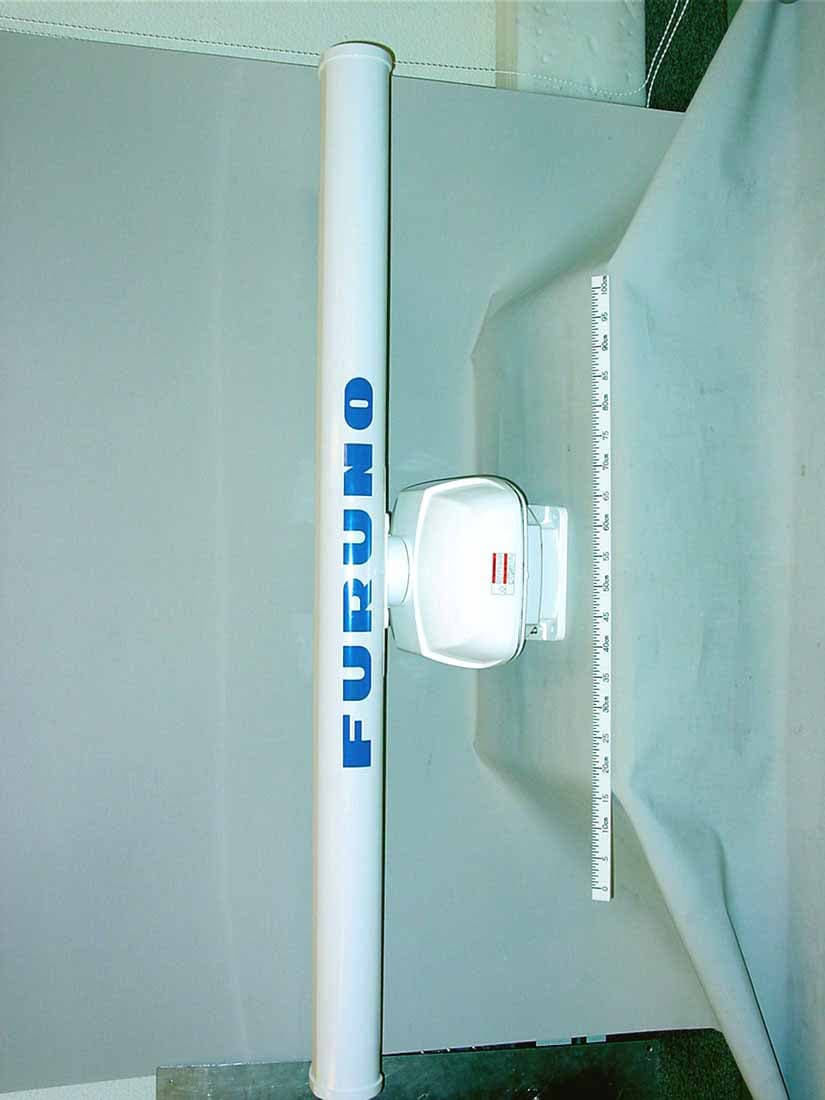
Click to zoom
Application Details
- Equipment Class
- MRD - Marine Radar
- Date of Grant
- Oct 27, 2005
- Application Purpose
- Original Equipment
- Date of Application
- Oct 06, 2005
- Equipment Note
- Marine Radar
- Frequency Range
- 9380.00000000 - 9440.00000000
- Company
- Furuno USA Inc
- Country
- United States
Documents & Files
Document Text
Text extracted from the exhibit documents filed with the FCC. Open a document above to read the original.
Users Manual
MARINE RADAR FR-8062, FR-8122, FR-8252 i SAFETY INSTRUCTIONS WARNING Radio Frequency Radiation Hazard The radar antenna emits electromagnetic radio frequency (RF) energy which can be harmful, particularly to your eyes. Never look directly into the antenna aperture from a close distance while the radar is in operation or expose yourself to the transmitting antenna at a close distance. Distances at which RF radiation levels of 100 and 10 W/m 2 exist are given in the table below. Note: If the antenna unit is installed at a close distance in front of the wheel house, your administration may require halt of transmission within a certain sector of antenna revolution. This is possible. Ask your FURUNO representative or dealer to provide this feature. MODEL Distance to 100 W/m 2 point Distance to 10 W/m 2 point FR-8062 Nil Worst case 2.50 m Worst case 2.30 m XN-12A XN-13A XN-12A XN-13A Worst case 0.50 m Worst case 0.30 m Worst case 7.50 m Worst case 7.00 m FR-8122 XN-12A XN-13A Worst case 0.80 m Worst case 0.70 m Worst case 9.50 m Worst case 9.00 m FR-8252 ii WARNING ELECTRICAL SHOCK HAZARD Do not open the equipment. Only qualified personnel should work inside the equipment. Turn off the radar power switch before servicing the antenna unit. Post a warn- ing sign near the switch indicating it should not be turned on while the antenna unit is being serviced. Prevent the potential risk of being struck by the rotating antenna and exposure to RF radiation hazard. Wear a safety belt and hard hat when working on the antenna unit. Serious injury or death can result if someone falls from the radar antenna mast. Do not disassemble or modify the equipment. Fire, electrical shock or serious injury can result. Turn off the power immediately if water leaks into the equipment or the equip- ment is emitting smoke or fire. Continued use of the equipment can cause fire or electrical shock. WARNING Use the proper fuse. Fuse rating is shown on the equipment. Use of a wrong fuse can result in damage to the equipment. Keep heater away from equipment. Heat can alter equipment shape and melt the power cord, which can cause fire or electrical shock. Do not place liquid-filled containers on the top of the equipment. Fire or electrical shock can result if a liquid spills into the equipment. Do not operate the equipment with wet hands. Electrical shock can result. iii WARNINGWARNING No one navigational aid should be relied upon for the safety of vessel and crew. The navigator has the responsibility to check all aids available to confirm position. Electronic aids are not a substitute for basic navigational principles and common sense. • This ARP automatically tracks automatically or manually acquired radar targets and calculates their courses and speeds, indicating them by vectors. Since the data generated by the auto plotter are based on what radar targets are selected, the radar must always be optimally tuned for use with the auto plotter, to ensure required targets will not be lost or unwanted targets such as sea returns and noise will not be acquired and tracked. • A target does not always mean a land- mass, reef, ships or other surface vessels but can imply returns from sea surface and clutter. As the level of clutter changes with environment, the operator should properly adjust the A/C SEA, A/C RAIN and GAIN controls to be sure target echoes are not eliminated from the radar screen. CAUTION The plotting accuracy and response of this ARP meets IMO standards. Tracking accuracy is affected by the following: • Tracking accuracy is affected by course change. One to two minutes is required t o restore vectors to full accuracy after an abrupt course change. (The actual amount depends on gyrocompass specifications.) • The amount of tracking delay is inversely proportional to the relative speed of the target. Delay is on the order of 15—30 seconds for high relative speed; 30—60 seconds for low relative speed. The data generated by ARP, AIS and video plotter are intended for reference only. Refer to official nautical charts for detailed and up-to-date information. iv WARNING To avoid electrical shock, do not remove cover. No user-serviceable parts inside. WARNING LABEL Warning labels are attached to the equipment. Do not remove any label. If a label is missing or damaged, contact a FURUNO agent or dealer about replacement. WARNINGARNING Radiation hazard. Only qualified personnel should work inside scanner. Confirm that TX has stopped before opening scanner. DISPLAY UNIT Name:Warning Label (1) Type:86-003-1011-0 Code No.: 100-236-230 ANTENNA UNIT Name:Radiation Warning Label Type:03-142-3201-0 Code No.: 100-266-890 TFT LCD The high quality TFT (Thin Film Transistor) LCD displays 99.999% of its picture ele- ments. The remaining 0.01% may drop out or light, however this is an inherent property of the LCD; it is not a sign of malfunction. v TABLE OF CONTENTS FOREWORD ............................................................................................... ix SYSTEM CONFIGURATION ...................................................................... xi 1. OPERATIONAL OVERVIEW .............................................................. 1-1 1.1Controls .....................................................................................................................1-1 1.2Turning the Radar On/Off, Transmitting ....................................................................1-4 1.3Display Indications.....................................................................................................1-5 1.4Display Brilliance, Panel Dimmer ..............................................................................1-6 1.5Menu Overview..........................................................................................................1-6 1.6Tuning........................................................................................................................1-7 1.7Presentation Modes............................…
Text truncated - open the document above for the full version.
Cover Letter(s)
Federal Communications Commission Office of Engineering and Technology 445 12th Street, SW Washington, DC 20554 Request for Confidentiality Dear Sir or Madam, In regard to the FCC application for ID ADB9ZWRTR087 The following documents are company confidential, containing technical information of a proprietary nature. Circuit Diagrams/Schematics Operational Description I respectfully request that documents of this category be kept confidential. Thank you for your assistance. Best regards, Shane Ryan Type Acceptance Commercial Service FURUNO USA Inc. (360) 834-9300 X5060 (360) 834- 833-5195 [email protected]
External Photos
Furuno Labotech International Co., Ltd Document number: FLI 01-05-016 Date of issue: 30 June 2005 - Page 1 of 3 - Photographs of the Furuno Radar FR-8252 with Transceiver RTR-087 included 1 External View 1.1 Antenna unit RSB-0073 (with Transceiver RTR-087 contained) 1.1.1 Front View Furuno Labotech International Co., Ltd Document number: FLI 01-05-016 Date of issue: 30 June 2005 - Page 2 of 3 - 1.1.2 Rear View ID Label is affixed on the Scanner Case of the Antenna unit. Furuno Labotech International Co., Ltd Document number: FLI 01-05-016 Date of issue: 30 June 2005 - Page 3 of 3 - 1.1.3 Name Plate (ID Label)
ID Label/Location Info
Furuno Labotech International Document number: FLI 01-05-027 Date of issue: 30 June 2005 Form: Q053/01 - Page 1 of 2 - Identification of Equipment for the Furuno Radar FR-8252 with Transceiver RTR-087 included (FCC Rule, 2.925) 1 ID Label The following nameplates are permanently fixed on the corresponding equipment units. FCC ID: ADB9ZWRTR087 Material of Nameplate: Polyester film, 0.2 mm thick Photo. 1.1 Name Plate for Antenna unit Including FCC ID Photo. 1.2 Name Plate for Display unit Furuno Labotech International Document number: FLI 01-05-027 Date of issue: 30 June 2005 Form: Q053/01 - Page 2 of 2 - 2 ID Label Location Photo. 2 ID Label Location
Internal Photos
Furuno Labotech International Co., Ltd Document number: FLI 01-05-028 Date of issue: 30 June 2005 - Page 1 of 5 - Photographs of the Furuno Radar FR-8252 with Transceiver RTR-087 included 1 Internal View 1.1 Antenna unit RSB-0073 1.1.1 Inside View (with Top cover opened, showing Scanner Motor (upper) and Transceiver RTR-087 (lower)) Furuno Labotech International Co., Ltd Document number: FLI 01-05-028 Date of issue: 30 June 2005 - Page 2 of 5 - 1.1.2 Transceiver Top View (with RTB shield-cover removed, showing RTB Board 03P9405 (right),IF AMP Board enclosed by shield-cover (center), Magnetron (top), Circulator (center left), Limiter (lower left) and MIC (bottom left)) Furuno Labotech International Co., Ltd Document number: FLI 01-05-028 Date of issue: 30 June 2005 - Page 3 of 5 - 1.1.3 Transceiver Top View (with IF AMP’s shield-cover removed, showing IF AMP Board 03P9404 (center)) Furuno Labotech International Co., Ltd Document number: FLI 01-05-028 Date of issue: 30 June 2005 - Page 4 of 5 - 1.1.4 Transceiver Bottom View Furuno Labotech International Co., Ltd Document number: FLI 01-05-028 Date of issue: 30 June 2005 - Page 5 of 5 - 1.1.5 Transceiver Bottom View (with shield-cover removed, showing MD 03P9239 (left), RFC 03P9238 (upper right) Boards and Pulse Transformer (lower right))
Parts List/Tune Up Info
Furuno Labotech International Co., Ltd. Document no.: FLI 01-05-053 Date of issue: 6 October 2005 PARTS LIST of Antenna units for FURUNO Marine radar Types: FR-8XX2 series including Transceiver RTR-085/-086/-087 Antenna units of this equipment contain the complex modules, printed circuit boards and major discrete parts. These are listed below: 1 FR-8062 (TX power: 6 kWpeak) Function modules/ Major discrete parts Module type/ Type number Remarks 1 Antenna unit 1.1 Scanner RSB-0070, RSB-0073 24 rpm, 24/36/48 rpm Antenna drive motor RM8025, RM8711 24 rpm, 24/36/48 rpm Reed switch RS 1 NO/ 03S8621 1.2 Transceiver RTR-085 1.2.1 RTB Board 03P9405 1.2.2 IF AMP Board 03P9404 1.2.3 MD Board 03P9235 1.2.4 RRV Board 03P9323 Magnetron MAF1422B, MG4006 Circulator RC4356 Limiter RU9099 MIC (Microwave Integrated Circuit) RU9731 1.3 Radiator XN12A, XN13A 4-ft type, 6-ft type Furuno Labotech International Co., Ltd. Document no.: FLI 01-05-053 Date of issue: 6 October 2005 2 FR-8122 (TX power: 12 kWpeak) Function modules/ Major discrete parts Module type/ Type number Remarks 1 Antenna unit 1.1 Scanner RSB-0073 24/36/48 rpm Antenna drive motor RM8711 24/36/48 rpm, Reed switch RS 1 NO/ 03S8621 1.2 Transceiver RTR-086 1.2.1 RTB Board 03P9405 1.2.2 IF AMP Board 03P9404 1.2.3 PTU Board 03P9236 1.2.4 MD Board 03P9237 Magnetron MAF1425B Circulator RC4356 Limiter RU9099 MIC (Microwave Integrated Circuit) RU9731 HV (Pulse) transformer RT4427 1.3 Radiator XN12A, XN13A 4-ft type, 6-ft type Furuno Labotech International Co., Ltd. Document no.: FLI 01-05-053 Date of issue: 6 October 2005 3 FR-8252 (TX power: 25 kWpeak) Function modules/ Major discrete parts Module type/ Type number Remarks 1 Antenna unit 1.1 Scanner RSB-0073 24/36/48 rpm Antenna drive motor RM8711 24/36/48 rpm Reed switch RS 1 NO/ 03S8621 1.2 Transceiver RTR-087 1.2.1 RTB Board 03P9405 1.2.2 IF AMP Board 03P9404 1.2.3 RFC Board 03P9238 1.2.4 MD Board 03P9239 Magnetron M1458(F) Circulator RC4356 Limiter RU9099 MIC (Microwave Integrated Circuit) RU9731 HV (Pulse) transformer RT9023 Fan motor MMS-06C24DS-R01/ 03S9110 1.3 Radiator XN12A, XN13A 4-ft type, 6-ft type
Parts List/Tune Up Info
3-1 3. SETTING UP THE EQUIPMENT 3.1 Opening the Installation Menu After you have installed the equipment, set up the equipment as follows. 1. Press the MENU key. The main menu appears on the screen. 2. Rotate the trackball downward to choose Installation. The installation menu appears in gray to right side of the screen. 3. While pressing down the CANCEL/HL OFF key, press the MENU key five times. [ENTER]: Enter [CANCEL/HL OFF]: Back [MENU]: Exit System GPS Mark Target Trails Custom 1 Custom 2 Custom 3 Target ARP AIS Tuning Type View Position Input Source Language Purpose Antenna Height Heading Adjust : Center : Main : 5 m : 0 ° : 8062 : English : Sea Tuning Initial Adjust Manual MBS Adjust Auto Installation Setup Manual Timing Adjust Local Time Offset : 0 : - 0.1 H : 0 Menu Installation Initial Factory Sector Blank 1 Installation Total TX Time : 000000.5 h (Total On Time: 000000.6 h)* * : Displayed when scrolled. 4. Press the ENTER key. The highlighted cursor appears in the Installation menu. 5. Rotate the trackball downward or upward to choose an item in the Installation menu. 6. Press the ENTER key to show setting window. 7. Rotate the trackball downward or upward to choose an option. 8. Press the ENTER key to set it. 9. Finally, press the MENU key to close the main menu. Basic settings Language: The default setting is English. Choose an appropriate language. Purpose: Choose the purpose of this radar among River, Sea and IEC. The default setting is Sea. River: To use this radar on the river Sea: To use this radar at oceans. IEC: To use this radar as the type approved radar. Type: Choose type of this radar among 8062 (6 kW radar), 8122 (12 kW radar) and 8252 (25 kW radar) to coincide with the specifications of the antenna unit. The default setting is 8062. Unsuitable setting may result malfunctions. 3. SETTING UP THE EQUIPMENT 3-2 View Position: Choose an operating position for this radar among Left, Left-Center, Center, Right-Center and Right to view the colors (echo, background, characters, etc.) correctly. The default setting is Center. Left: When operating this radar at the left side. Left-Center: When operating this radar at the left-center side. Center: When operating this radar at center position. Right-Center: When operating this radar at the right-center side. Right: When operating this radar at the right side. Input Source: Choose the input source between Main and Sub. The default setting is Main. Main: When using this display unit as main radar. Sub: When using this display unit as sub display. Antenna Height: Choose a position of the antenna unit from the sea level among 5, 10, 15, 20, 30, 40 and 50 m. The default setting is 5 m. Local Time Offset: To display a local time on the screen, set the time difference from the UTC. Heading Adjustment You have mounted the antenna unit facing straight ahead in the direction of the bow. Therefore, a small but conspicuous target dead ahead visually should appear on the heading line (zero degrees). In practice, you will probably observe some small error on the display because of the difficulty in achieving accurate initial positioning of the antenna unit. The following adjustment will compensate for this error. 1. Set ship’s heading toward a suitable target (for example, ship or buoy) at a range between 0.125 and 0.25 nautical mile. 2. Transmit the radar at 0.25 nm range and measure the bearing of that target relative to ship’ heading with EBL. 3. Open the Installation menu, and choose Heading Adjust. 4. Press the ENTER key to show the HEADING ADJUST window. S S 0 ° (0 ° ∼ 359 °) 5. Rotate the trackball upward or downward to set the value measured at the step 2 above. 6. Press the ENTER and confirm that the target shows dead ahead on the screen. 3-3 Auto Installation Setup When this item is executed, the tune adjustment, timing adjustment, video adjustment and MSB adjustment are automatically done. 1. Transmit the radar at 48 nm range. 2. Choose Auto Installation Setup at the installation menu and press the ENTER key. 3. Rotate the trackball to choose Yes, and then press the Enter key. Automatically, the tune adjustment begins, indicating “Tuning adjusting....” Then, the timing adjustment, video adjustment and MSB adjustment are execute automatically, indicating “Timing adjustment...”, “Video adjustment...”, and “MSB adjustment...” in that order. After adjustment, the window disappears. If you do not satisfy the result of the Auto Installation Setup, execute Manual Timing Adjust, Tuning Initial Adjust and Manual MSB Adjust as follows. Tuning Initial Adjust 1. Transmit the radar. 2. Open the Installation menu, and choose Tuning Initial Adjust. 3. Press the ENTER key to show the setting window. 4. Rotate the trackball to choose Yes, and then press the Enter key. The tune adjustment begins, indicating “Tuning adjusting....” After adjustment, the window disappears. Manual Timing Adjust This adjustment ensures proper radar performance, especially on short ranges. The radar measures the time required for a transmitted echo to travel to the target and return to the source. The received echo appears on the display based on this time. Thus, at the instant the transmitter is fired, the sweep should start from the center of the display (sometimes called sweep origin.) A trigger pulse generated in the display unit goes to the antenna unit through the signal cable to trigger the transmitter (magnetron). The time taken by the signal to travel up to the antenna unit varies, depending largely on the length of signal cable. During this period the display unit should wait before starting the sweep. When the display unit is not adjusted correctly, the echoes from a straight local object (for example, a harbor wall or straight pier) will not appear with straight edges – namely, they will be seen as “pushed out” or “pulled in” near the picture center. The range of objects will also be incorrectly shown. (1) Target pulled (2) Correct (3) Target pushed outward…
Text truncated - open the document above for the full version.
Test Report
This report shall not be reproduced except in full, without the written approval of Furuno Labotech International Co., Ltd. TECHNICAL INFORMATION TEST REPORT ON THE PERFORMANCE OF MARINE RADAR Brand Name : FURUNO Transceiver Type : RTR-087 Report no.: FLI 12-05-027 Date of issue: June 30, 2005 Furuno Labotech International Co., Ltd. 9-52 Ashihara-cho, Nishinomiya City, Hyogo 662-8580, Japan Tel: +81-798-63-1094 Fax: +81-798-63-1098 Furuno Labotech International Report no.: FLI 12-05-027 Form: Q053/01 - Page 1 of 39 - All tests were performed in Furuno Labotech International Co., Ltd. All data herein contained is true and correct to our best knowledge. Tested by: Katusmi Imamura/Assistant Chief Engineer, Technical Section Reviewed by: Sadatomo Kuwahara/Chief Engineer, Technical Section Approved by: Mitsuyoshi Komori/Manager, Technical Section Date: June 30, 2005 Name: Mitsuyoshi Komori Manager, Technical Section Signature: Furuno Labotech International Report no.: FLI 12-05-027 Form: Q053/01 - Page 2 of 39 - * * * * * * C O N T E N T S * * * * * * 1 General Information.............................................................................................................................. 3 2 Identification of Equipment (FCC Rule, 2.925)................................................................................. 10 3 Test data.............................................................................................................................................. 11 3.1 RF Power Output (FCC Rule, 2.1046).................................................................................................. 11 3.2 Modulation Characteristics (FCC Rule, 2.1047).................................................................................. 14 3.3 Occupied Bandwidth (FCC Rule, 2.1049) ............................................................................................ 22 3.4 Spurious Emissions at Antenna Terminal (FCC Rule, 2.1051) ............................................................ 24 3.5 Field Strength of Spurious Radiation (FCC Rule, 2.1053) ................................................................... 28 3.6 Frequency Stability (FCC Rule, 2.1055) ............................................................................................... 30 3.7 Suppression of Interference Aboard Ships (FCC Rule, 80.217) .......................................................... 33 4 Photographs to Reveal Equipment Construction and Layout (FCC Rule, 2.1033)...................... 37 5 Description of Circuitry and Devices (FCC Rules, 2.1033)............................................................. 38 6 Operator’s Manual Incl. Circuit Diagrams (FCC Rule, 2.1033)....................................................... 39 Attachment A [ Test data for 3.4 Spurious Emissions at Antenna Terminal ] Attachment B [ Test data for 3.5 Field Strength of Spurious Radiation ] Attachment C [ Test data for 3.7 Suppression of Interference Aboard Ships ] Attachment D [ List of Test/ Measuring Equipment ] Furuno Labotech International Report no.: FLI 12-05-027 Form: Q053/01 - Page 3 of 39 - 1 General Information 1.1 General (a) Manufacturer: Furuno Electric Co., Ltd. Ashihara-cho 9-52, Nishinomiya-city, 662-8580 Japan (b) Model: FR-8252 Type Serial Number Display unit RDP-150 4332-0002 Antenna unit RSB-0073 Antenna rotation rate: 24/36/48 rpm Transceiver: RTR-087 Contained in Antenna unit Radiator (*): XN12A XN13A Power supply unit PSU-008 R151-0002 Note: (*) - 1 (one) selectable (c) Primary Function: Search, Navigation and anticollison (d) Discrimination Range Discrimination:20 meters on a range scale of 1.5 nm Bearing Discrimination: Radiator type: XN12A XN13A Discrimination (°):1.90 1.35 (e) Minimum Range: 20 meters on a range scale of 0.25 nm (f) Frequency Range: Fixed frequency, X-band Type of Emission: P0N (g) Power Supply: 12 - 24 VDC 1.2 Antenna Unit 1.2.1 Transceiver Type: RTR-087 (1) Transmitter (a) Assignable Frequency for Shipborne Radar: Between 9300 and 9500 MHz (FCC Rule, 80.375 (d)-(1)) (b) Type of RF Generator Magnetron Type: M1458 (F) Peak Output Power: 25 kW nominal Furuno Labotech International Report no.: FLI 12-05-027 Form: Q053/01 - Page 4 of 39 - (c) Magnetron Ratings Center frequency of Magnetron:9410 MHz Tolerances M1458 (F) Manufacturing: 30 MHz Pulling: 26 MHz Tolerance for 20°C temperature variation: -5 MHz (d) Guard Band: Guard Band is specified to be equal to 1.5/T MHz, where "T" is the pulselength in microseconds. See para (e). (FCC Rule, 80.209(b)) (e) Pulse Characteristics: Range Scale (nm) (Short ) (Middle)(Long 1)(Long 2) (Long 3) 0.125 0.25 0.5 0.75 1.0 1.5 1.5 2 3 3 4 6 8 12 16 24 36 48 64 72 96 Pulselength (s) 0.08 0.30 0.80 0.80 0.80 P.R.R.(Hz) 2100 1200 600 550 500 Duty cycle 1.68X10 -4 3.60X10 -4 4.80X10 -4 4.40X10 -4 4.00X10 -4 Guard Band (MHz) 18.75 5.00 1.88 1.88 1.88 Note 1: Tests were carried out for the underlined Range Scales. Furuno Labotech International Report no.: FLI 12-05-027 Form: Q053/01 - Page 5 of 39 - (2) Modulator (a) FET Type: 2SK1464 Trigger Voltage: Approx. +20 VDC positive (3) Receiver (a) Passband (MHz) RF Stage: 60 MHz IF Stage: Pulselength Short Middle Long 1Long 2Long 3 (MHz) 40 2.5 2.5 2.5 2.5 (b) Gain (overall) (dB): Sufficient to cause limiting, approximately 100 (c) Overall Noise Figure (dB): 5.0 (typical) (d) Video Output Voltage (V): 4 V negative (e) Features Provided: Sensitivity Time Controls (Anti-clutter Sea), Fast Time Constant (Anti-clutter Rain) (f) If receiver is tunable, describe method of adjusting frequency: Adjustment of tuning voltage of receiver local oscillator (Automatic and manual) 1.2.2 Antenna (a) Antenna Rotation ON-OFF Switch: Not Provided. (b) Reflector: Slotted array antenna Radiator type: XN12A XN13A Length (cm): 120 180 Length (ft): 3.9 5.9 (c) Type of Beam: Vertical fan (d) Beam Width (between half-Radiator power points) Radiator type: XN12A XN13A Horizontal 1.90° 1.35° Vertical 22° 22° (e) …
Text truncated - open the document above for the full version.
Contact Information
Applicant
Bill Haynes(Deep Sea Product Manager)
Technical Specifications
| # | Rule Parts | Frequency Range | Power Output | Emission | Tolerance |
|---|---|---|---|---|---|
| 1 | 90 | 9.38 GHz - 9.44 GHz | 25000 W | 71M3P0N | 3000.0000000000 Hz |
Other Applications from Furuno USA Inc
ADB-9ZWRTR137
Feb 18, 2026Transceiver unit for the radar sensor
Equipment Class
MRD - Marine RadarADB9ZWRTR136
Jul 01, 2024Transceiver unit for the radar sensor
Equipment Class
MRD - Marine Radar
ADB9ZWRTR128
Apr 06, 2022Transceiver unit for the radar sensor
Equipment Class
MRD - Marine Radar
ADB9ZWRTR133
Sep 26, 2021Transceiver unit for the radar sensor
Equipment Class
MRD - Marine Radar
ADB9ZWRTR129
May 23, 2021Transceiver unit for the radar sensor
Equipment Class
MRD - Marine Radar