ADB9ZWRTR087AMarine Radar
Furuno USA Inc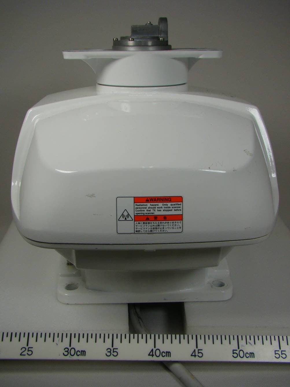
Click to zoom
Application Details
- Equipment Class
- MRD - Marine Radar
- Date of Grant
- Jun 21, 2011
- Application Purpose
- Original Equipment
- Date of Application
- Apr 27, 2011
- Equipment Note
- Marine Radar
- Frequency Range
- 9300.00000000 - 9500.00000000
- Company
- Furuno USA Inc
- Country
- United States
Documents & Files
Document Text
Text extracted from the exhibit documents filed with the FCC. Open a document above to read the original.
Users Manual
Installation Manual MARINE RADAR FR-8062/8122/8252 SYSTEM CONFIGURATION ............................................................................................................... ii EQUIPMENT LISTS..............................................................................................................................iv 1. MOUNTING................................................................................................................................. 1-1 1.1 Antenna Unit.......................................................................................................................... 1-1 1.2 Display Unit ......................................................................................................................... 1-12 1.3 Power Supply Unit............................................................................................................... 1-15 2. WIRING ....................................................................................................................................... 2-1 2.1 Standard Wiring..................................................................................................................... 2-1 2.2 Wiring the Power Supply Unit ...............................................................................................2-2 2.3 Port for External Devices ...................................................................................................... 2-4 3. SETTING UP THE EQUIPMENT ................................................................................................ 3-1 3.1 Setting Language .................................................................................................................. 3-1 3.2 Opening the Installation Menu ..............................................................................................3-2 4. OPTIONAL EQUIPMENT............................................................................................................ 4-1 4.1 ARP Kit ARP-11..................................................................................................................... 4-1 4.2 External Monitor .................................................................................................................... 4-3 4.3 Remote Display ..................................................................................................................... 4-5 4.4 External Buzzer ..................................................................................................................... 4-7 PACKING LIST, INSTALLATION MATERIALS, SPARE PARTS ..................................................... A-1 OUTLINE DRAWINGS......................................................................................................................D-1 INTERCONNECTION DIAGRAMS ................................................................................................... S-1 All brand and product names are trademarks, registered trademarks or service marks of their respective holders. www.furuno.co.jp 9-52, Ashihara-cho, Nishinomiya, 662-8580, JAPAN Telephone: +81-(0)798-65-2111 Fax: +81-(0)798-65-4200 FURUNO Authorized Distributor Dealer All rights reserved. Pub. No. IME-35390-H FR-8062/8122/8252 (AKMU) A:SEP. 2005 H :MAR. 31, 2011 Printed in Japan (Elemental Chlorine Free) The paper used in this manual is elemental chlorine free. i SAFETY INSTRUCTIONS WARNING MODEL Distance to 100 W/m 2 point Distance to 10 W/m 2 point 0.7 m WARNING ELECTRICAL SHOCK HAZARD FR-8122 XN-12A 2.1 m Observe the following compass safe distances to prevent deviation of a magnetic compass. Standard Steering Display unit 0.95 m 0.60 m 0.80 m0.50 m CAUTIONCAUTION Power supply unit Antenna unit FR-8062 (24 rpm) 1.95 m1.25 m FR-8062 XN-12A (4') 0.9 m FR-8062 XN-13A (6') FR-8122 XN-13A 1.9 m FR-8252 XN-12A 4.6 m 0.4 m FR-8252 XN-13A 0.4 m 3.1 m 1.90 m1.20 m 1.10 m0.70 m 1.80 m1.15 m FR-8062 (48 rpm) FR-8122 FR-8252 Indicates a condition that can cause death or serious injury if not avoided. Indicates a condition that can cause minor or moderate injury if not avoided. Read these safety instructions before you operate the equipment. WARNING CAUTION Warning, Caution Prohibitive Action Mandatory Action Radio Frequency Radiation Hazard The radar antenna emits electromagnetic radio frequency (RF) energy which can be harmful, particularly to your eyes. Never look directly into the antenna aperture from a close distance while the radar is in operation or expose yourself to the transmitting antenna at a close distance. Distances at which RF radiation levels of 100 and 10 W/m 2 exist are given in the table below. Note: If the antenna unit is installed at a close distance in front of the wheel house, your administration may require halt of transmission within a certain sector of antenna revolution. Do not open the equipment unless totally familiar with electrical circuits and service manual. Only qualified personnel should work inside the equipment. Wear a safety belt and hard hat when working on the antenna unit. Serious injury or death can result if someone falls from the radar mast. Construct a suitable service platform from which to install the antenna unit. Serious injury or death can result if someone falls from the radar mast. Turn off the power at the mains switchboard before beginning the installation. Fire, electrical shock or serious injury can result if the power is left on or is applied while the equipment is being installed. ii SYSTEM CONFIGURATIONS FR-8062/8122 ANTENNA UNIT RSB-0073-085A-XN12A/XN13A: FR-8062 RSB-0073-086A-XN12A/XN13A: FR-8122 DISPLAY UNIT RDP-150 Auto Plotter ARP-11 (built in display unit) AC-DC Power Supply PR-240 100/110/ 115/220/ 230 VAC, 1 φ 12-24 VDC Remote Display Commercial Monitor (SVGA or better) Gyro Converter AD-100 Heading Sensor PG-1000 NMEA DEVICE NMEA DEVICE External Buzzer OP03-136 : Optional equipment Gyrocompass Category of units Antenna unit: Exposed to weather All oth…
Text truncated - open the document above for the full version.
Users Manual
2. WIRING 2-2 2.2 Wiring the Power Supply Unit Cabling 1. Unfasten four screws to remove the cable clamp. 2. Unfasten four screws to remove the cover. 3. Attach the connectors of three cables as shown in the figure below. POWER Board 03P9419 J1 3P VL3P-VV-S2X 2C-AA050 cable (to 12-24 VDC) MJ-B24 LPF0011-050 cable (to display unit) V H 9 N H 13 V H 4 J3 J4 J5 Ground terminal V H 1 0 J12 N H 1 4 J14 V H 5 J13 V H 2 J11 Antenna cable RW-9771 (03S9771) 4. Lay three cables in respective slots referring to the figure above. 5. Reattach the cover and the cable clamp. 6. Connect a ground wire (local supply, IV-2sq) between the ground terminal and ship’s ground. 2. WIRING 2-3 Jumper block, slide switch setting The jumper block JP1 and slide switch S112 on the PWR board (03P9419) must be set according to radar model. Open the unit, locate JP1 and S112 and set them as below. FR-8252 S S112 T MODEL1964C Jumper block JP1 ("short" for FR-8252 radar; remove dummy connector and attach connector assy. XH2P-L40-ACR.) Slide switch S112 (Upward position for FR-8252) Power supply unit, inside view Jumper block, slide switch Function Setting JP1 Enables/disables motor slow start circuit. Short (disable) S112 TUNE voltage selector (0-12 V, 0-32 V) Upward position (0-12 V) Power requirement, replacement of fuses Power requirement The power for the power supply unit and display unit must be drawn from the same power switch on the power terminal board. Replacement of fuses The power supply unit is shipped with a 15 A fuse(for connection to 12 VDC battery). Replace the fuse with a 7 A (supplied) when the ship’s battery is 24 VDC. 2. WIRING 2-4 2.3 Port for External Devices External equipments can be connected here as shown below. NMEA1(7P) NMEA2(7P) HDG (6P) PC/EXT-BUZZER (7P) NMEA sentence device NMEA sentence device Heading sensor External buzzer, PC, etc. This equipment can receive the following NMEA 0183 format sentences from other equipment. You will need the optional NMEA cable to connect with external equipment. • Course: VTG> RMC • Waypoint Range: BWR> BWC> RMB, Bearing: BWR> BWC (> RMB* 1 ) • Heading (True): HDT> VHW> HDG* 2 > HDM* 2 > VHW* 2 • Heading (Magnetic): HDG> HDM> VHW> HDT* 2 > VHW* 2 • Ship’s speed: Over ground: VTG>RMC> VHW, Through water: VHW • Date: ZDA • Time: ZDA • Own ship’s position: GNS>GGA>RMC> GLL • Depth: DPT>DBT • Wind speed and angle* 3 : True: MWV>VWT, Relative: MWV>VWR • Water temperature: MTW *1: Available when true bearing. *2: Variation data is required. *3: True or Relative is changed with menu. 3-1 3. SETTING UP THE EQUIPMENT 3.1 Setting Language At the first power application after installation, choose a language as follows. 1. Press /BRILL key to turn the power on. “Now Initializing...” appears and after a while the window below appears. Language English Language Francais Language Espanol Language Deutsch Language Italiano Language Portugues Language Dansk Language Svensk Language Norsk Language Chinese Language Japanese Language Thai 2. Rotate the trackball to choose language desired and press the ENTER key. The confirmation window appears. Yes No Language English OK? Changes with language chosen. 3. Choose Yes and press the ENTER key. 3. SETTING UP THE EQUIPMENT 3-2 3.2 Opening the Installation Menu After you have installed the equipment, set it up as follows. 1. Press the MENU key. The main menu appears on the screen. 2. Rotate the trackball downward to choose Installation. The installation menu appears in gray to right side of the screen. 3. While pressing down the CANCEL/HL OFF key, press the MENU key five times to activate the Installation menu. [ENTER]: Enter [CANCEL/HL OFF]: Back [MENU]: Exit System GPS Mark Custom 1 Custom 2 Custom 3 Target ARP AIS Tuning Type View Position Input Source Language Purpose Antenna Height Heading Adjust : Center : Main : 5 m : 0 ° : 8062 : English : Sea Tuning Initial Adjust Manual MBS Adjust Auto Installation Setup** Manual Timing Adjust Local Time Offset : 0 : - 0.1 H : 0 Menu Installation Initial Factory Sector Blank 1** Installation Total TX Time* : 000000.5 h Total On Time* : 000000.6 h * : Displayed when scrolled. Memory Clear* ** : Set the Sector Blank to "Off" in order to execute Auto Installation Setup in the Installation menu. GPS Buoy Video Initial Adjust : 0 Antenna Rotation : Rotate 4. Press the ENTER key. The highlighted cursor appears in the Installation menu. 5. Rotate the trackball downward or upward to choose an item in the Installation menu. 6. Press the ENTER key to show setting window. 7. Rotate the trackball downward or upward to choose an option. 8. Press the ENTER key to confirm setting. 9. Finally, press the MENU key to close the main menu. Basic Settings Language: Choose an appropriate language. Purpose: Choose the purpose of this radar among River, Sea and IEC. The default setting is Sea. River: To use this radar on a river. Sea: To use this radar on high seas. IEC: To use this radar as the type approved radar. Type: Choose type of this radar among 8062 (6 kW radar), 8122 (12 kW radar) and 8252 (25 kW radar) to agree with the specifications of the antenna unit. The default setting is 8062. Unsuitable setting may result in malfunction. 3. SETTING UP THE EQUIPMENT 3-3 View Position: Choose the operating position for this radar among Left, Left-Center, Center, Right-Center and Right to view echo colors correctly. The default setting is Center. Left: When operating this radar at the left side. Left-Center: When operating this radar at the left-center side. Center: When operating this radar at center position. Right-Center: When operating this radar at the right-center side. Right: When operating this radar at the right side. Approx. angle of the view position as follows. LCD screen 30 15 30 15 0 Left Left-Center Center Right Right-Center Note: The radar echo and trail echo are adjusted by the View Position. The characters are not adjusted. This setting is also reflected on an external monitor (option). Input Sou…
Text truncated - open the document above for the full version.
Cover Letter(s)
Federal Communications Commission Office of Engineering and Technology 445 12th Street, SW Washington, DC 20554 To whom it may concern, We hereby respectfully request that under the provision of KDB Publication 726920, the following documents submitted in support of this application for ADB9ZWRTR087A certification be provided with confidential status. Schematics Parts list/Tune up info Operational description These documents contain trade secrets that are treated as confidential by us. Substantial competitive harm to our company business could result should they be made available to the public. Best regards , Shane Ryan Type Acceptance Commercial Service FURUNO USA Inc. (360) 834-9300 X5060 (360) 834- 833 -5195 [email protected]
Cover Letter(s)
6/8/2011 Federal Communications Commission Office of Engineering and Technology 445 12th Street, SW Washington, DC 20554 To whom it may concern, We hereby respectfully request that under the provision of FCC rules section0.457(d) and0.459, the following documents submitted in support of this application for ADB9ZWRTR087A certification be provided with confidential status. Schematics Parts list/Tune up info Operational description These documents contain trade secrets that are treated as confidential by us. Substantial competitive harm to our company business could result should they be made available to the public. Best regard Shane Ryan Type Acceptance Commercial Service FURUNO USA Inc. (360) 834-9300 X5060 (360) 834- 833 -5195 [email protected]
External Photos
Furuno Labotech International Co., Ltd. Document number: FLI 01-11-009 Date of issue: 15 March 2011 - Page 1 of 3 - Photographs of Antenna unit RSB-0073 with Transceiver RTR-087A for Furuno Radar FR-8252 1 External View 1.1 Front View Furuno Labotech International Co., Ltd. Document number: FLI 01-11-009 Date of issue: 15 March 2011 - Page 2 of 3 - 1.2 Rear View ID Label is affixed on the Scanner Case of the Antenna unit. Furuno Labotech International Co., Ltd. Document number: FLI 01-11-009 Date of issue: 15 March 2011 - Page 3 of 3 - 1.3 Name Plate (ID Label)
ID Label/Location Info
Furuno Labotech International Document number: FLI 01-11-017 Date of issue: 15 March 2011 Form: Q053/01 - Page 1 of 2 - Identification of Equipment for the Furuno Radar Transceiver RTR-087A (FCC Rule, 2.925) 1 ID Label The following nameplate is permanently fixed on the corresponding equipment unit. FCC ID: ADB9ZWRTR087A Material of Nameplate: Polyester film, 0.2 mm thick Furuno Labotech International Document number: FLI 01-11-017 Date of issue: 15 March 2011 Form: Q053/01 - Page 2 of 2 - 2 ID Label Location ID Label is affixed on the Scanner Case of the Antenna unit.
Internal Photos
Furuno Labotech International Co., Ltd. Document number: FLI 01-11-010 Date of issue: 15 March 2011 - Page 1 of 6 - Photographs of Antenna unit RSB-0073 with Transceiver RTR-087A for Furuno Radar FR-8252 1 Internal View 1.1 Inside View (with Top cover opened, showing Scanner Motor (upper) and Transceiver RTR-087A (lower)) Furuno Labotech International Co., Ltd. Document number: FLI 01-11-010 Date of issue: 15 March 2011 - Page 2 of 6 - 1.2 Transceiver Top View (with RTB shield-cover removed, showing RTB Board 03P9405 (right), IF AMP Board enclosed by shield-cover (center), Magnetron (top center), Circulator (center left), Limiter (lower left) and MIC (bottom left)) Furuno Labotech International Co., Ltd. Document number: FLI 01-11-010 Date of issue: 15 March 2011 - Page 3 of 6 - 1.3 Transceiver Right side View (with IF AMP’s shield-cover removed, showing IF AMP Board 03P9404 (center)) Furuno Labotech International Co., Ltd. Document number: FLI 01-11-010 Date of issue: 15 March 2011 - Page 4 of 6 - 1.4 Transceiver Left side View Circulator Limiter Filter Isolator Magnetron Furuno Labotech International Co., Ltd. Document number: FLI 01-11-010 Date of issue: 15 March 2011 - Page 5 of 6 - 1.5 Transceiver Bottom View Furuno Labotech International Co., Ltd. Document number: FLI 01-11-010 Date of issue: 15 March 2011 - Page 6 of 6 - 1.6 Transceiver Bottom View (with shield-cover removed, showing MD Board 03P9239 (left), RFC Board 03P9238 (upper right) and Pulse Transformer (lower right))
Test Report
This report shall not be reproduced except in full, without the written approval of Furuno Labotech International Co., Ltd. Test Report (FCC Rules 2.1046/2.1047/2.1049/2.1051/2.1053/2.1055/80.217) For Trade name: Furuno Model: Transceiver for Marine Radar Type: RTR-087A Report no.: FLI 12-11-031 Date of issue: 15 March 2011 Furuno Labotech International Co., Ltd. 1-16 Fukazu-cho, Nishinomiya-shi, Hyogo 663-8203, Japan Tel: +81-798-63-1094 Fax: +81-798-63-1098 Furuno Labotech International Report no.: FLI 12-11-031 Form: FQ053/04 - Page 2 of 37 - Report Summary FLI project number: FLI 04-10-0339 Test report number: FLI 12-11-031 Date of Initial Issue: 15 March 2011 Revision number: --- Date of Revised Issue: --- Test report revision made: Rev. no. Date PageItemDescription of change --- --- --- --- --- Test standard(s)/ Test specifications: FCC 47 CFR, Sections: 2.1046 - RF Power Output, 2.1047 - Modulation Characteristics, 2.1049 - Occupied Bandwidth, 2.1051 - Spurious Emissions at Antenna Terminal, 2.1055 - Frequency Stability, 2.1053 - Field Strength of Spurious Radiation, 80.217 - Suppression of Interference Aboard Ships. (Date of issue: 1 October 2010) Customer: Furuno Electric Co., Ltd. 9-52 Ashihara-Cho, Nishinomiya-City, 662-8580 Japan Manufacturer: Furuno Electric Co., Ltd. 9-52 Ashihara-Cho, Nishinomiya-City, 662-8580 Japan Trade name: FURUNO Model: Transceiver for Marine Radar Type: RTR-087A Product function and intended use: For Marine Safety navigation Number of samples tested: One Serial number: R199-0001 Power rating: 12 - 24 VDC, 120 W (for Display Unit) (The EUT was powered through the Display unit, not directly from DC mains) Product status: Pre-production model Modifications made to samples during testing: None. Date of receipt of samples: 13 January 2011 Test period: 13 January 2011 to 4 February 2011 Place of test: Furuno Labotech International Co., Ltd. - Nishinomiya Lab. 9-52 Ashihara-Cho, Nishinomiya City, Hyogo Prefecture, 662-8580 Japan - Nishinomiya-Hama Lab. 2-20 Nishinomiya-Hama, Nishinomiya City, Hyogo Prefecture, 662-0934 Japan Anechoic Chamber used for the test has been registered by FCC. (File number: 90607) Test results/ Compliance: Passed. The test results of this report relate only to the samples tested. Tested by: Katsumi Imamura and Akira Inoue Written by: Akiko Inoue Verified by: Yoshihiro Ishii Approved by: Date: 15 March 2011 Name: Yoshihiro Ishii Title: Manager, Technical Section, Furuno Labotech International Co., Ltd. Signature: Furuno Labotech International Report no.: FLI 12-11-031 Form: FQ053/04 - Page 3 of 37 - Testing Laboratory Status Furuno Labotech International Co., Ltd. (hereafter called FLI) has been holding the following status after having been assessed according to the provisions of ISO/IEC 17025 and/or the relevant rules: (1) Telefication Listed Testing Laboratory: - listed by Telefication B. V., Edisonstraat 12a, 6902 PK Zevenaar, The Netherlands - Laboratory assignment number: L116 - Date of initial certification: 26 July 1999 (*) - for testing the following product categories/ test standards: - EN 60945, Maritime navigation and radiocommunication equipment and systems - General requirements. - IEC 61162-1/-2, Maritime navigation and radiocommunication equipment and systems - Digital interfaces - Part 1: Single talker and multiple listeners / Part 2: Single talker and multiple listeners, high speed transmission. (2) BSH Recognized Testing Laboratory: - recognized by Bundesamt für Seeschifffahrt und Hydrographie, Bernhad-Nocht-Str. 78, 20359 Hamburg, Federal Republic of Germany - Recognition certificate number: BSH4613/06201/0835/08 - Date of initial certification: 4 April 2003 (*) - for testing in the fields of: “Marine navigational and radiocommunication equipment and systems” - EMC and environmental tests according to: IEC 60945: 2002, DIN EN 60945: 2003 - Radar - Shipborne navigational displays IEC 60936-1: 1999, DIN EN 60936-1: 2000 IEC 62288: 2008 IEC 60936-2: 1998, DIN EN 60936-2: 1999 (3) TÜV Appointed EMC Test Laboratory: - appointed by TÜV Rheinland Japan Ltd., 19-5 Shin Yokohama 3-chome, Kohoku-ku, Yokohama 222-0033 Japan - Laboratory assignment number: UA 50046428 - Date of initial certification: 21 December 1998 (*) - for carrying out the tests of: - EN 55022, CISPR 22, EN 61000-3-2/-3, EN/IEC 61000-4-2/-3/-4/-5/-6/-8/-11, EN/IEC 61000-6-1/-2, EN/IEC 61000-6-3/-4, EN/IEC 60945, EN/IEC 61326-1, EN/IEC 61326-2-6, EN/IEC 60601-1-2, JIS T 0601-1-2, JIS C 1806-1, EN 55011, CISPR 11. (4) RMRS Recognized Testing Laboratory: - recognized by Russian Maritime Register of Shipping, 8, Dvortsovaya Nab., St. Petersburg, 191186 Russia - Laboratory recognition number : 09.00110.011 - Date of initial certification : 27 January 2009 (*) - for carrying out testing in the field of : 21001301 Elecrtrical measurements and tests, 21001302 EMC tests, 21001500 Mechanical measurements and tests, 21002000 Equipment protection degree tests, and 21002100 Climatic tests for Ship’s radio and navigational equipment and IEC 60945 : 2002 Note: (*) – The current certificates may be found in the FLI web site (http://www.furuno-labotech.co.jp). Furuno Labotech International Report no.: FLI 12-11-031 Form: FQ053/04 - Page 4 of 37 - TABLE OF CONTENTS Report Summary ............................................................................................................................. 2 Testing Laboratory Status ............................................................................................................. 3 1 Principal Information ................................................................................................................... 5 1.1 Equipment under test (EUT) ................................................................................................... 5 1.2 Observation and comments .................................................................................................... 7 2 Test Results Summary .......…
Text truncated - open the document above for the full version.
Contact Information
Applicant
Bill Haynes(Deep Sea Product Manager)
Technical Contact
FURUNO USAShane Ryan
[email protected]360 834-9300
4400 NW Pacific Rim blvd · Camas, Washington · United States
Technical Specifications
| # | Rule Parts | Frequency Range | Power Output | Emission |
|---|---|---|---|---|
| 1 | 80 | 9.30 GHz - 9.50 GHz | 25000 W | 71M3PON |
Other Applications from Furuno USA Inc
ADB-9ZWRTR137
Feb 18, 2026Transceiver unit for the radar sensor
Equipment Class
MRD - Marine RadarADB9ZWRTR136
Jul 01, 2024Transceiver unit for the radar sensor
Equipment Class
MRD - Marine Radar
ADB9ZWRTR128
Apr 06, 2022Transceiver unit for the radar sensor
Equipment Class
MRD - Marine Radar
ADB9ZWRTR133
Sep 26, 2021Transceiver unit for the radar sensor
Equipment Class
MRD - Marine Radar
ADB9ZWRTR129
May 23, 2021Transceiver unit for the radar sensor
Equipment Class
MRD - Marine Radar