ADB9ZWRTR088BTransceiver for Radar model FR-8045
Furuno USA Inc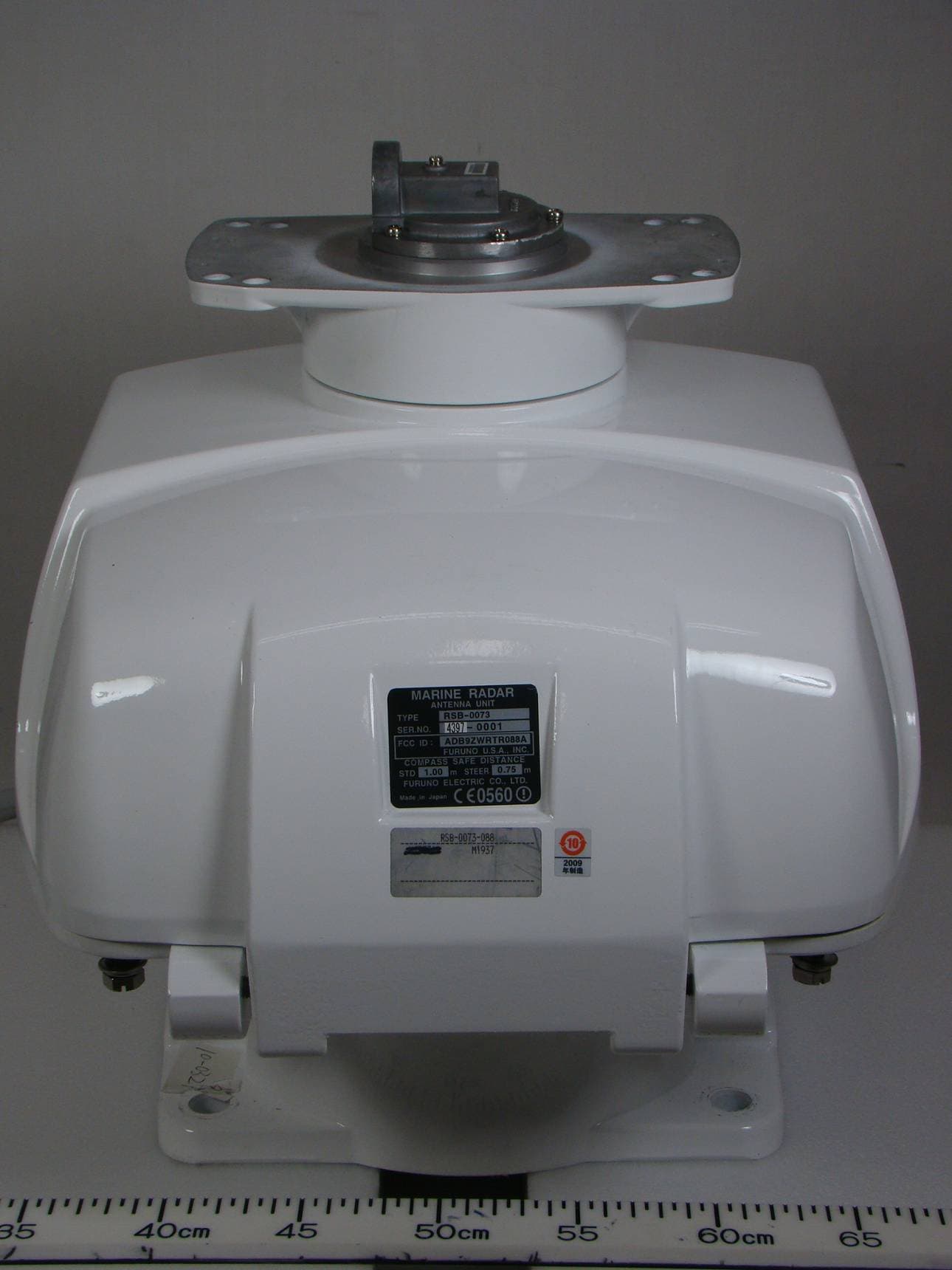
Click to zoom
Application Details
- Equipment Class
- MRD - Marine Radar
- Date of Grant
- May 12, 2014
- Application Purpose
- Original Equipment
- Date of Application
- May 11, 2014
- Equipment Note
- Transceiver for Radar model FR-8045
- Frequency Range
- 9410.00000000 - 9410.00000000
- Company
- Furuno USA Inc
- Country
- United States
Documents & Files
Document Text
Text extracted from the exhibit documents filed with the FCC. Open a document above to read the original.
Users Manual
Furuno Labotech International Co., Ltd. Document number: FLI 01-10-048 Date of issue: 5 January 2011 - Page 4 of 16 - Photographs of the Antenna unit with the Transceiver RTR-088A included for Furuno Marine Radar MODEL 1937 2 Inside View 2.1 Inside front view (with top lid opened.) Transceiver module Furuno Labotech International Co., Ltd. Document number: FLI 01-10-048 Date of issue: 5 January 2011 - Page 5 of 16 - 2.2 Inside front view RTB Board Furuno Labotech International Co., Ltd. Document number: FLI 01-10-048 Date of issue: 5 January 2011 - Page 6 of 16 - 2.3 Inside front view (with Transceiver module removed.) Furuno Labotech International Co., Ltd. Document number: FLI 01-10-048 Date of issue: 5 January 2011 - Page 7 of 16 - 2.4 Transceiver front view (with shield cover for IF Board 03P9404 removed.) Furuno Labotech International Co., Ltd. Document number: FLI 01-10-048 Date of issue: 5 January 2011 - Page 8 of 16 - 2.5 Transceiver right view Magnetron Furuno Labotech International Co., Ltd. Document number: FLI 01-10-048 Date of issue: 5 January 2011 - Page 9 of 16 - 2.6 Transceiver rear view Circulator Magnetron Isolator Filter Furuno Labotech International Co., Ltd. Document number: FLI 01-10-048 Date of issue: 5 January 2011 - Page 10 of 16 - 2.7 Transceiver left view MIC Furuno Labotech International Co., Ltd. Document number: FLI 01-10-048 Date of issue: 5 January 2011 - Page 11 of 16 - 2.8 Transceiver bottom view Furuno Labotech International Co., Ltd. Document number: FLI 01-10-048 Date of issue: 5 January 2011 - Page 12 of 16 - 2.9 Transceiver bottom view (with shield cover removed, showing MD Board 03P9235)
Users Manual
www.furuno.com All brand and product names are trademarks, registered trademarks or service marks of their respective holders. Installation Manual MULTI-COLOR LCD RADAR Model FR-8045/FR-8065/FR-8125/FR8255 SAFETY INSTRUCTIONS ................................................................................................ i SYSTEM CONFIGURATION ........................................................................................... ii EQUIPMENT LISTS........................................................................................................ iii 1. HOW TO INSTALL THE SYSTEM ............................................................................. 1 1.1 Display Unit........................................................................................................................... 1 1.2 Antenna Unit Installation ....................................................................................................... 5 1.3 Power Supply Unit .............................................................................................................. 19 2. CABLE CONNECTION AND WIRING20 2.1 Standard Connection ..........................................................................................................20 2.2 Wiring the Power Supply Unit (FR-8255 only) .................................................................... 21 2.3 Data Signals........................................................................................................................ 23 2.4 Input/Output Ports............................................................................................................... 23 3. EQUIPMENT SETTINGS.......................................................................................... 25 3.1 Setting the Language.......................................................................................................... 25 3.2 How to Set the Purpose ......................................................................................................26 3.3 How to Enter Initial Settings................................................................................................27 4. OPTIONAL EQUIPMENT ......................................................................................... 31 4.1 ARP Kit ARP-11.................................................................................................................. 31 4.2 Connection of Buzzer and/or Remote Display .................................................................... 33 PACKING LISTS ......................................................................................................... A-1 OUTLINE DRAWINGS ................................................................................................ D-1 INTERCONNECTION DIAGRAMS.............................................................................. S-1 i SAFETY INSTRUCTIONS WARNING Radio Frequency Radiation Hazard WARNING CAUTIONCAUTION CAUTIONCAUTION WARNING Indicates a condition that can cause death or serious injury if not avoided. CAUTION Indicates a condition that can cause minor or moderate injury if not avoided. Warning, Caution Mandatory Action Prohibitive Action Read these safety instructions before you operate the equipment. Do not open the equipment unless totally familiar with electrical circuits and service manual. Only qualified personnel should work inside the equipment. Wear a safety belt and hard hat when working on the antenna unit. Serious injury or death can result if someone falls from the radar mast. Construct a suitable service platform from which to install the antenna unit. Serious injury or death can result if someone falls from the radar mast. Turn off the power at the mains switchboard before beginning the installation. Fire, electrical shock or serious injury can result if the power is left on or is applied while the equipment is being installed. Ground the equipment to prevent electrical shock and mutual interference. Observe the following compass safe distances to prevent deviation of a magnetic compass. The radar antenna emits electromagnetic radio frequency (RF) energy which can be harmful, particularly to your eyes. Never look directly into the antenna aperture from a close distance while the radar is in operation or expose yourself to the transmitting antenna at a close distance. Distances at which RF radiation levels of 100 W/m 2 and 10 W/m 2 exist are given in the table below. Note: If the antenna unit is installed at a close distance in front of the wheel house, your administration may require halt of transmission within a certain sector of antenna revolution. This is possible - Ask your FURUNO representative or dealer to provide this feature. FR-8065 100W/m 2 10W/m 2 FR-8125 FR-8255 FR-8045 Model Display Unit RDP-154 FR-8065 Antenna FR-8125 Antenna FR-8255 Antenna FR-8045 Antenna 1.00m 1.95m 0.65m 1.25m PSU-008 0.80m 0.50m RSB-0070 RSB-0070 RSB-0070 RSB-0073 RSB-0073 RSB-0073 1.90m 1.00m 1.10m 1.85m 1.80m 0.95m 1.20m 0.60m 0.70m 1.25m 1.15m 0.60m Model Standard Steering XN-12A XN-13A XN-12A XN-13A XN-12A XN-13A XN-12A XN-13A N/A N/A N/A N/A N/A N/A 1.1m 1.0m 1.9m 0.6m 0.4m3.1m 4.6m 1.7m 2.1m 1.9m ii SYSTEM CONFIGURATION Note 1: 12 VDC cannot be used with this equipment. Note 2: When replacing the antenna, make sure the correct SPU board is used, referring to the table below. ModelSPU Board FR-804503P9586B FR-8065/FR-8125/FR-825503P9586A 24 VDC Display unit RDP-154 External buzzer Echo sounder GPS navigator AIS, etc. Remote display : Basic configuration Heading sensor Echo sounder GPS navigator AIS, etc. : Optional Model FR-8065 Antenna Unit XN-12A-RSB-0070-085A XN-12A-RSB-0073-085A XN-13A-RSB-0070-085A XN-13A-RSB-0073-085A Model FR-8125 Antenna Unit XN-12A-RSB-0070-086A XN-12A-RSB-0073-086A XN-13A-RSB-0070-086A XN-13A-RSB-0073-086A Model FR-8255 Antenna Unit XN-12A-RSB-0070-087A XN-12A-RSB-0073-087A XN-13A-RSB-0070-087A XN-13A-RSB-0073-087A 24 VDC Antenna Power Supply PS…
Text truncated - open the document above for the full version.
Users Manual
20 2.CABLE CONNECTION AND WIRING 2.1Standard Connection Connect all necessary cables, using the figure and table below for reference. No.Description Cable Required 1 Antenna cable to antenna unit (FR-8045)MJ-B24LPF0005-*+R *: 50/100/150/200/300 Antenna cable to antenna unit. (FR-8065/8125) MJ-B24LPF0012-*+R *: 100/150/200/300 Antenna cable to antenna unit. (FR-8255) • MJ-B24LPF0011-050+R • RW-9771 (10m, 15m, 20m, 30m) • VL3P-VV-S2X2C-AA050 2USB (Used by service man only). 3Heading Sensor. (AD-10 format) (MJ-A6SPF0007-100C) 4NMEA1 input/output. (Navigational equipment)(MJ-A7SPF0007-050C) 5NMEA2 input/output. (Navigational equipment)(MJ-A7SPF0007-050C) 6Option. (External buzzer, Remote display) (See section 4.2 for cabling.) 7Power in. To ship’s power (pos = white, neg = black) (MJ-A3SPF0017-050ZC) 8Grounding. Connect from here to ship’s terminal.IV-2sq. Ground the equipment to prevent interference. CAUTION 1 2 3 4 5 6 7 8 2. CABLE CONNECTION AND WIRING 21 2.2Wiring the Power Supply Unit (FR-8255 only) 2.2.1Cabling 1. Unfasten four screws to remove the cable clamp. 2. Unfasten four screws to remove the cover. 3. Attach the connectors of three cables as shown in the figure below. 4. Lay three cables in respective slots referring to the figure above. 5. Reattach the cover and the cable clamp. 6. Connect a ground wire (local supply, IV-2sq) between the ground terminal and ship’s ground. POWER Board 03P9419 J1 3P VL3P-VV-S2X 2C-AA050 cable (to 12-24 VDC) MJ-B24 LPF0011-050 cable (to display unit) V H 9 N H 13 V H 4 J3 J4 J5 Ground terminal V H 1 0 J12 N H 1 4 J14 V H 5 J13 V H 2 J11 Antenna cable RW-9771 (03S9771) 2. CABLE CONNECTION AND WIRING 22 2.2.2Jumper block, slide switch setting The jumper block JP1 and slide switch S112 on the PWR board (03P9419) must be set according to radar model. Open the unit, locate JP1 and S112 and set them as below. 2.2.3Power requirement, replacement of fuses Power requirement The power for the power supply unit and display unit must be drawn from the same power switch on the power terminal board. Replacement of fuses The power supply unit is shipped with a 15 A fuse(for connection to 12 VDC battery). Replace the fuse with a 7 A (supplied) when the ship’s battery is 24 VDC. Jumper block, slide switch FunctionSetting JP1Enables/disables motor slow start circuit. Short (disable) S112TUNE voltage selector (0-12 V, 0-32 V)Upward position (0-12 V) Jumper block JP1 ("short" for FR-8255 radar; remove dummy connector and attach connector assy. XH2P-L40-ACR.) Slide switch S112 (Set to upward position for “FR-8252”) 2. CABLE CONNECTION AND WIRING 23 2.3Data Signals 2.4Input/Output Ports 2.4.1HDG port This port is for AD-10 format. PositionGNS>GGA>RMC> GLL Course true VTG>RMC Course magneticVTG>RMC (true) Speed over the groundVTG>RMC Water speed and headingVHW Distance to waypointBWR>BWC>RMB Destination waypoint, trueBWR>BWC>RMB Destination waypoint, magneticBWR>BWC Heading (true)THS>HDT>VHW (true)>HDG>HDM>VHW (magnetic) Heading (magnetic)HDG> HDM>VHW (magnetic)THS>HDT>VHW (true) Magnetic variationHDG>RMC Cross-track errorXTE>RMB DepthDPT>DBT TemperatureMTW Wind (true)MWV>VWT Wind (relative)MWV>VWR TimeZDA ParameterRatingRemarksCircuit Diagram Forward Current 50mAAbsolute Maximum Reverse Voltage 6VAbsolute Maximum Forward Voltage 1.1V (TYP) 1.4V (MAX) I F =4mA ParameterRatingRemarksCircuit Diagram Forward Current 50mAAbsolute Maximum Reverse Voltage 6VAbsolute Maximum Forward Voltage 1.1V (TYP) 1.4V (MAX) I F =4mA Photocoupler 490Ω GYRO_DATA_H GYRO_DATA_C Photocoupler 490Ω GYRO_CLK_H GYRO_CLK_C 2. CABLE CONNECTION AND WIRING 24 2.4.2NMEA1 ports Transmitter This port complies with “IEC 61162-1 Ed4”. Receiver This port complies with “IEC 61162-1 Ed4”. 2.4.3NMEA2 ports This port complies with “IEC 61162-1 Ed4”. Circuit specification is the same as NMEA1 port. ParameterRatingRemarksCircuit Diagram “H” level output current -60mAAbsolute Maximum “L” level output current 60mAAbsolute Maximum Differential output voltage 1.5V (MIN) 5V (MAX) Load 54Ω ParameterRatingRemarksCircuit Diagram Forward Current 50mAAbsolute Maximum Reverse Voltage 6VAbsolute Maximum Forward Voltage 1.1V (TYP) 1.4V (MAX) I F =4mA Differential Driver TD1_A TD1_B Photocoupler 490Ω RD1_H RD1_C 25 3.EQUIPMENT SETTINGS 3.1Setting the Language After installation, on first power-up, select a language as follows: 1. Press the /BRILL key to turn on the power. "Now Initializing" appears and after a short time the window below appears. 2. Use the CursorPad to select a language required and press the ENTER key. The window shown below appears. 3. Select [Yes] and press the ENTER key. Language selected Language English OK? Yes No 3. EQUIPMENT SETTINGS 26 3.2How to Set the Purpose 1. Press the MENU key. The main menu will appear on the screen. 2. Press the S or T button to select [Factory]. The factory menu title bar will appear in gray color right side of the screen. 3. Hold down the CANCEL/HL OFF key and press the MENU key five times to acti- vate the [Factory] menu. 4. Press the ENTER key. The [Factory] menu becomes active and the cursor moves to the right-hand column. 5. Press S or T to select [Purpose]. 6. Press the ENTER key to show the setting window. 7. Press S or T to select the purpose required. 8. Press the ENTER key to set the purpose. 9. Press the CANCEL/HL OFF key to return to the main menu. Menu Factory Language Purpose Purpose Model : English : Sea : 8065 RTR-085A The model name depends on your radar model. Do not change the model name. ARPA AIS GPS System [Enter]: Enter [CANCEL/HL OFF]: Back [Menu]: Exit Use this menu when setting up in factory Initial Tests Sector Blanks Units Installation Factory River Sea IEC Russian River 3. EQUIPMENT SETTINGS 27 3.3How to Enter Initial Settings After you complete setting the radar purpose, enter the Initial Settings as follows: 1. On the main menu, press S or T to select [Installation]. 2. Press the ENTER key. The [Installation] menu becomes active and the cursor m…
Text truncated - open the document above for the full version.
Users Manual
OPERATOR'S MANUAL www.furuno.com MODEL FR-8065 FR-8045 FR-8125 FR-8255 PRODUCT NAME: MARINE RADAR MULTI-COLOR LCD RADAR The paper used in this manual is elemental chlorine free. ・FURUNO Authorized Distributor/Dealer 9-52 Ashihara-cho, Nishinomiya, 662-8580, JAPAN A:JAN2014 . Printed in Japan All rights reserved. A1:FEB.07, 2014 Pub. No. OME-36320-A1 ( GREG ) FR-8045/8065/8125 0 0 0 1 7 8 5 0 2 1 0 i IMPORTANT NOTICES General How to discard this product Discard this product according to local regulations for the disposal of industrial waste. For disposal in the USA, see the homepage of the Electronics Industries Alliance (http://www.eiae.org/) for the correct method of disposal. How to discard a used battery Some FURUNO products have a battery(ies). To see if your product has a battery, see the chapter on Maintenance. Follow the instructions below if a battery is used. Tape the + and - terminals of battery before disposal to prevent fire, heat generation caused by short circuit. In the European Union The crossed-out trash can symbol indicates that all types of batteries must not be discarded in standard trash, or at a trash site. Take the used batteries to a battery collection site according to your national legislation and the Batteries Directive 2006/66/EU. In the USA The Mobius loop symbol (three chasing arrows) indicates that Ni-Cd and lead-acid rechargeable batteries must be recycled. Take the used batteries to a battery collection site according to local laws. In the other countries There are no international standards for the battery recycle symbol. The number of symbols can increase when the other countries make their own recycle symbols in the future. • This manual has been authored with simplified grammar, to meet the needs of international users. • The operator of this equipment must read and follow the descriptions in this manual. Wrong oper- ation or maintenance can cancel the warranty or cause injury. • Do not copy any part of this manual without written permission from FURUNO. • If this manual is lost or worn, contact your dealer about replacement. • The contents of this manual and equipment specifications can change without notice. • The example screens (or illustrations) shown in this manual can be different from the screens you see on your display. The screens you see depend on your system configuration and equipment settings. • Save this manual for future reference. • Any modification of the equipment (including software) by persons not authorized by FURUNO will cancel the warranty. • All brand and product names are trademarks, registered trademarks or service marks of their re- spective holders. • Ricoh bitmap font is a trademark or registered trademark of Ricoh Company, Ltd. Cd Ni-CdPb ii SAFETY INSTRUCTIONS WARNING Radio Frequency Radiation Hazard WARNING Indicates a condition that can cause death or serious injury if not avoided. CAUTION Indicates a condition that can cause minor or moderate injury if not avoided. Warning, Caution Mandatory Action Prohibitive Action Read these safety instructions before you operate the equipment. The radar antenna sends the electromagnetic radio frequency (RF) energy. This energy can be dangerous to you, especially your eyes. Do not look at the radiator or near the antenna when the antenna is rotating. The distances at which RF radiation levels of 100 W/m 2 and 10 W/m 2 exist are shown in the table. Note: If the antenna unit is installed at a close distance in front of the wheel house, prevent the transmission in that area to protect passengers and crew from microwave radiation. Set the [Sector Blanks] in the [System] menu. FR-8065 100W/m 2 10W/m 2 FR-8125 FR-8255 FR-8045 Model XN-12A XN-13A XN-12A XN-13A XN-12A XN-13A XN-12A XN-13A N/A N/A N/A N/A N/A N/A 1.1m 1.0m 1.9m 0.6m 0.4m3.1m 4.6m 1.7m 2.1m 1.9m SAFETY INSTRUCTIONS iii WARNING ELECTRICAL SHOCK HAZARD Do not open the equipment. Only qualified persons can work inside the equipment. Turn off the power before you service the antenna unit. Post a warning sign near the power switch not to turn on the power while you service the antenna unit. Prevent the potential risk of being struck by the rotating antenna and exposure to RF radiation hazard. Do not disassemble or modify the equipment. Fire or electrical shock can occur. Turn off the power immediately if water leaks into the equipment or smoke or fire is coming from the equipment. Failure to turn off the equipment can cause fire or electrical shock. Use the correct fuse. A wrong fuse can damage the equipment and cause fire. Keep heater away from the equipment. Heat can change the equipment shape and melt the power cord, which can cause fire or electrical shock. Do not put liquid-filled containers on the top of the equipment. Fire or electrical shock can occur if a liquid spills into the equipment. Do not operate the equipment with wet hands. Electrical shock can occur. WARNING SAFETY INSTRUCTIONS iv Do not depend on one navigation device for the navigation of the ship. The navigator must check all aids available to confirm position. Electronic aids are not a replacement for basic navigation principles and common sense. · The ARPA automatically tracks an automatically or manually acquired radar target and calculates its course and speed, indicating them by a vector. Since the data from the auto plotter depend on the selected radar targets, the radar must be optimally tuned for use with the auto plotter, to ensure required targets will not be lost or unnecessary targets like sea returns and noise will not be acquired and tracked. · A target is not always a landmass, reef, ship, but can also be returns from the sea surface and from clutter. As the level of clutter changes with the environment, the operator must correctly adjust the A/C SEA, A/C RAIN and GAIN controls so that the target echoes do not disappear from the radar screen. CAUTIONCAUTION The plotting accuracy and response of this ARPA meets IMO standards. The tracking accu…
Text truncated - open the document above for the full version.
Users Manual
1. OPERATION 1-21 1.19Target Alarm The target alarm looks for targets (ship, landmass, etc.) in the area you set. When a target enters or exits the alarm area, audiovisual alarms are released. 1.19.1How to set a target alarm zone The following procedure shows you how to set a target alarm zone. 1. Press the TARGET ALARM key to activate ALARM 1 or ALARM 2. Press the TARGET ALARM key to change the active ALARM between No. 1 and No. 2. The indication of the currently active ALARM is in a rectangle at the upper-right corner of the screen. 2. Use the CursorPad to move the cursor to the position A and press the ENTER key. 3. Move the cursor to the position B and press the ENTER key. The rectangle that shows alarm status indication at the upper-right corner of the screen disappears. (See figure below) Note 1: To set a 360-degree guard zone, set the position B in the same bearing as the position A. Note 2: When the target alarm zone is not within the range in use, the indica- tion"ALM1(or 2)_RNG" replaces "ALM1(or 2)_IN(or OUT)" in the alarm status area. (When the target alarm zone is within the range of full off-centering, the indication does not change.) Select a range which displays the target alarm zone. CAUTIONCAUTION · Do not depend on the alarm as the only means to detect possible collision situations. · Adjust the A/C SEA, A/C RAIN and GAIN controls correctly so that the alarm system does not miss the target echoes. Cursor + Target alarm zone 1 (Length of dash and interval for alarm zone 2 are longer than alarm zone 1.) A B Alarm status ALM1_IN ALM2_OUT 1. OPERATION 1-22 1.19.2How to stop the audio alarm When a target enters (or exits) the target alarm zone, the target flashes and the alarm sounds. The alarm message appears at the bottom of the screen. To stop the audio alarm, press any key. When the target enters (or exits) the target alarm zone again, the audio alarm sounds. 1.19.3How to select the alarm type You can set the target alarm to activate against targets which enter or exit the alarm zone. In and Out target alarms 1. Press the MENU key to open the menu. 2. Use S or T to select [Alarm] and press the ENTER key. Alarm menu 3. Use S or T to select [Target Alarm 1] or [Target Alarm 2] then press the ENTER key. Target Alarm options 4. Use S or T to select [In] or [Out]. [In]: When the targets enter a target alarm zone, the alarm sounds. [Out]: When the targets exit a target alarm zone, the alarm sounds. 5. Press the ENTER key followed by the MENU key. “In” target alarm “Out” target alarm [ENTER]: Enter [MENU]: Exit [CANCEL/HL OFF]: Back Brill/Color Display Echo Custom 1 Custom 2 Custom 3 Alarm Target Trails Tuning Target Others Menu Echo Choosing the type (in/out) of target alarm 1 Target Alarm 1 Target Alarm 2 Alarm Level Watchman Panel Buzzer Alarm Status : In : In : Med : Off : On External Buzzer : On In Out 1. OPERATION 1-23 1.19.4How to sleep a target alarm temporarily When you do not require a target alarm temporarily, you can sleep the target alarm. The alarm zone remains on the screen, but, any targets that enter or exit the alarm zone do not trigger the audio and visual alarms. 1. Press the TARGET ALARM key to select the ALARM 1 or ALARM 2 indication at the upper-right corner on the screen. The selected indication is in a rectangle. 2. Press the CANCEL/HL OFF key. The alarm indication now shows "ALM1(or 2)_ACK". To activate a sleeping target alarm zone, press the TARGET ALARM key to select the ALARM 1 or ALARM 2 and press the ENTER key. The alarm indication then changes to "ALM1(or 2)_IN(or OUT)". 1.19.5How to deactivate a target alarm 1. Press the TARGET ALARM key to select the ALARM 1 or ALARM 2 indication at the upper-right corner on the screen. The selected indication is in a rectangle. 2. Press the CANCEL/HL OFF key. The alarm indication now shows "ALM1(or 2)_ACK". 3. Press the TARGET ALARM key. The alarm indication "ALM1(or 2)_ACK" is shown in a dashed-line rectangle. 4. Press the CANCEL/HL OFF key. The target alarm zone and the alarm indication are erased from the screen. 1.19.6How to select the target strength which triggers a target alarm You can select the target strength which triggers the target alarm as follows: 1. Press the MENU key to open the menu. 2. Use S or T to select [Alarm] and press the ENTER key. 3. Use S or T to select [Alarm Level] and press the ENTER key. 4. Use S or T to select the echo strength level. 5. Press the ENTER key followed by the MENU key. 1.19.7How to turn the buzzer on/off You can turn on/off the panel buzzer or external buzzer for target alarms. The panel buzzer is for this equipment. The external buzzer is for the optional buzzer, which is connected to this equipment to give the target alarm at a remote location. 1. Press the MENU key to open the menu. 2. Use S or T to select [Alarm] and press the ENTER key. 3. Use S or T to select [Panel Buzzer] (or [External Buzzer] for optional buzzer) and press the ENTER key. 4. Use the S or T to select [On] or [Off] then press the ENTER key. 5. Press the MENU key to close the menu. Low Med High Off On 1. OPERATION 1-24 1.20How to Off-center the Display You can off-center your ship position to expand the view field without selecting a larger range scale. The display can be off-centered manually, or automatically according to speed of the ship. Note: Off-centering is not available in the true motion mode and the 64 NM range scale or higher. 1.20.1How to select the off-center mode 1. Press the MENU key to open the menu. 2. Use S or T to select [Display] and press the ENTER key. 3. Use S or T to select [Offcenter Mode] and press the ENTER key. Offcenter Mode options 4. Use S or T to select [Manual], [Custom] or [Auto] then press the ENTER key. Press the ENTER key to change between on and off. 5. After setting all options, use the T to select [EXIT? YES] and press the ENTER key. 6. Press the MENU key to close the menu. 1.20.2Off-center the display Press the OFF CENTER key to move your ship positi…
Text truncated - open the document above for the full version.
Users Manual
www.furuno.com All brand and product names are trademarks, registered trademarks or service marks of their respective holders. Installation Manual MULTI-COLOR LCD RADAR Model FR-8045/FR-8065/FR-8125/FR8255 SAFETY INSTRUCTIONS ................................................................................................ i SYSTEM CONFIGURATION ........................................................................................... ii EQUIPMENT LISTS........................................................................................................ iii 1. HOW TO INSTALL THE SYSTEM ............................................................................. 1 1.1 Display Unit........................................................................................................................... 1 1.2 Antenna Unit Installation ....................................................................................................... 5 1.3 Power Supply Unit .............................................................................................................. 19 2. CABLE CONNECTION AND WIRING20 2.1 Standard Connection ..........................................................................................................20 2.2 Wiring the Power Supply Unit (FR-8255 only) .................................................................... 21 2.3 Data Signals........................................................................................................................ 23 2.4 Input/Output Ports............................................................................................................... 23 3. EQUIPMENT SETTINGS.......................................................................................... 25 3.1 Setting the Language.......................................................................................................... 25 3.2 How to Set the Purpose ......................................................................................................26 3.3 How to Enter Initial Settings................................................................................................27 4. OPTIONAL EQUIPMENT ......................................................................................... 31 4.1 ARP Kit ARP-11.................................................................................................................. 31 4.2 Connection of Buzzer and/or Remote Display .................................................................... 33 PACKING LISTS ......................................................................................................... A-1 OUTLINE DRAWINGS ................................................................................................ D-1 INTERCONNECTION DIAGRAMS.............................................................................. S-1 i SAFETY INSTRUCTIONS WARNING Radio Frequency Radiation Hazard WARNING CAUTIONCAUTION CAUTIONCAUTION WARNING Indicates a condition that can cause death or serious injury if not avoided. CAUTION Indicates a condition that can cause minor or moderate injury if not avoided. Warning, Caution Mandatory Action Prohibitive Action Read these safety instructions before you operate the equipment. Do not open the equipment unless totally familiar with electrical circuits and service manual. Only qualified personnel should work inside the equipment. Wear a safety belt and hard hat when working on the antenna unit. Serious injury or death can result if someone falls from the radar mast. Construct a suitable service platform from which to install the antenna unit. Serious injury or death can result if someone falls from the radar mast. Turn off the power at the mains switchboard before beginning the installation. Fire, electrical shock or serious injury can result if the power is left on or is applied while the equipment is being installed. Ground the equipment to prevent electrical shock and mutual interference. Observe the following compass safe distances to prevent deviation of a magnetic compass. The radar antenna emits electromagnetic radio frequency (RF) energy which can be harmful, particularly to your eyes. Never look directly into the antenna aperture from a close distance while the radar is in operation or expose yourself to …
Text truncated - open the document above for the full version.
Contact Information
Applicant
Bill Haynes(Deep Sea Product Manager)
Technical Specifications
| # | Rule Parts | Frequency Range | Power Output | Emission | Tolerance |
|---|---|---|---|---|---|
| 1 | 80 | 9.41 GHz - 9.41 GHz | 4000 W | 48M9P0N | 30000.0000000000 Hz |
Other Applications from Furuno USA Inc
ADB-9ZWRTR137
Feb 18, 2026Transceiver unit for the radar sensor
Equipment Class
MRD - Marine RadarADB9ZWRTR136
Jul 01, 2024Transceiver unit for the radar sensor
Equipment Class
MRD - Marine Radar
ADB9ZWRTR128
Apr 06, 2022Transceiver unit for the radar sensor
Equipment Class
MRD - Marine Radar
ADB9ZWRTR133
Sep 26, 2021Transceiver unit for the radar sensor
Equipment Class
MRD - Marine Radar
ADB9ZWRTR129
May 23, 2021Transceiver unit for the radar sensor
Equipment Class
MRD - Marine Radar