ADB9ZWRTR091AMarine Radar
Furuno USA Inc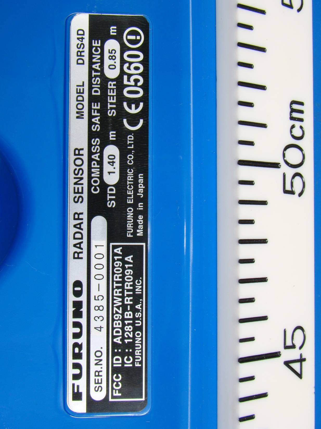
Click to zoom
Application Details
- Equipment Class
- MRD - Marine Radar
- Date of Grant
- Jan 04, 2012
- Application Purpose
- Original Equipment
- Date of Application
- Oct 20, 2011
- Equipment Note
- Marine Radar
- Frequency Range
- 9300.00000000 - 9500.00000000
- Company
- Furuno USA Inc
- Country
- United States
Documents & Files
Document Text
Text extracted from the exhibit documents filed with the FCC. Open a document above to read the original.
Users Manual
www.furuno.co.jp Installation Manual RADAR SENSOR DRS2D/DRS4D/ DRS4A/DRS6A/DRS12A/DRS25A SAFETY INSTRUCTIONS ............................................................................ i SYSTEM CONFIGURATION ....................................................................... ii EQUIPMENT LISTS.................................................................................... iv 1. MOUNTING ............................................................................................ 1 1.1Mounting Considerations .............................................................................................. 1 1.2Mounting Procedure for DRS2D/4D ............................................................................. 2 1.3Mounting Procedure for DRS4A/6A/12A/25A ............................................................... 3 1.4Mounting of Power Supply Unit PSU-013 (for DRS25A)/PSU-012 (Option) ................ 8 2. WIRING .................................................................................................. 9 2.1Wiring inside DRS2D/4D ............................................................................................ 12 2.2Wiring inside DRS4A/6A/12A/25A .............................................................................. 16 2.3Wiring inside Power Supply Unit PSU-013 (for DRS25A) .......................................... 20 2.4Wiring inside Power Supply Unit PSU-012 (Option) ................................................... 21 PACKING LISTS...................................................................................... A-1 OUTLINE DRAWINGS............................................................................. D-1 INTERCONNECTION DIAGRAMS.......................................................... S-1 i WARNING WARNING Wear a safety belt and hard hat when working on the antenna unit. Serious injury or death can result if someone falls from the radar mast. Model Distance to 100 W/m 2 point Distance to 10 W/m 2 point DRS4A Nil 1.20 m Nil 1.20 m The radar antenna emits electromagnetic radio frequency (RF) energy which can be harmful, particularly to your eyes. Never look directly into the antenna aperture from a close distance while the radar is in operation or expose yourself to the trans- mitting antenna at a close distance. Distances at which RF radiation levels of 100 and 10 W/m 2 exist are given in the table below. Note: If the antenna unit is installed at a close distance in front of the wheel house, your administration may require halt of transmission within a certain sector of antenna revolution. This is possible - Ask your FURUNO representive or dealer to provide this feature. CAUTION Do not open the equipment unless totally familiar with electrical circuits and service manual. Only qualified personnel should work inside the equipment. Observe the following compass safe distance to prevent deviation of a ma gnetic compass. Ground the equipment to prevent electrical shock and mutual interference. Construct a suitable service platform from which to install the antenna unit. Serious injury or death can result if the power is left on or is applied while the equipment is being installed. Turn off the power at the mains switch-board before beginning the installation. Fire, electrical shock or serious injury can result if the power is left on or is applied while the equipment is being installed. Model Standard Steering DRS4A 0.80 m 0.50 m DRS6A 0.85 m 0.55 m Radio Frequency Radiation Hazard DRS6A SAFETY INSTRUCTIONS DRS12A DRS2D Nil 0.40 m 0.10 m 1.40 m DRS4D DRS4D 1.40 m 0.85 m DRS2D 1.35 m 0.80 m 0.20 m 2.40 m DRS12A (XN12A) DRS12A (XN13A) 0.20 m 1.90 m 1.15 m 0.70 m PSU-012 0.30 m 0.30 m PSU-013 0.30 m 0.30 m DRS25A 1.00 m 0.60 m 0.50 m 5.30 m DRS25A (XN12A) DRS25A (XN13A) 0.40 m 4.40 m ii SYSTEM CONFIGURATION DRS2D/4D/4A/6A/12A RADAR SENSOR DRS4A/DRS6A/DRS12A OR RECTIFIER RU-1746B 100/110/220/230 VAC 12-24 VDC NMEA 2000 Equipment : Standard Supply : Optional Supply : Local Supply Multi Function Display BlackBox MFDBB Multi Function Display MFD8/12 Power Supply Unit PSU-012* *The power supply unit PSU-012 is necessary in the combination of radar sensor and MFD. NMEA 2000 Equipment RADAR SENSOR DRS2D/DRS4D MFD8 MFD12 MFDBB DRS2D/4D DRS4ADRS6A DRS12A (future development) NO NO NO NO NO NO NO YES YES YES YES NO 12-24 VDC iii DRS25A RADAR SENSOR DRS25A OR RECTIFIER RU-1746B 100/110/220/230 VAC 12-24 VDC NMEA 2000 Equipment : Standard Supply : Optional Supply : Local Supply Multi Function Display BlackBox MFDBB Multi Function Display MFD8/12 Power Supply Unit PSU-013 12-24 VDC iv EQUIPMENT LISTS Standard supply NameTypeCode No.QtyRemarks Radar SensorXN10A-RSB-118-092-1For DRS4A, w/CP03-32601 XN12A-RSB-118-0931For DRS6A, w/CP03-32601 XN12A-RSB-118-094-1For DRS12A, 1255 mm, w/CP03-32601 XN13A-RSB-118-0941For DRS12A, 1795 mm, w/CP03-32601 XN12A-RSB-118-095-1For DRS25A, 1255 mm, w/CP03- 32601 XN13A-RSB-118-095-1For DRS25A, 1795 mm, w/CP03- 32601 DRS2D-1Radome, 2 kW, w/CP03-32101 DRS4D-1Radome, 4 kW, w/CP03-32101 Power Supply Unit PSU-013-1For DRS25A, w/SP03-16101 and CP03-32700 Installation Materials CP03-32101001-025-270 1 set For DRS2D/4D CP03-32601001-025-780 1 set For DRS4A/6A/12A/25A CP03-32200000-011-7201Two-way cable, MOD-ASW0001- 100+, 10 m, for DRS2D/4D/4A/6A/12A CP03-32300000-011-721Two-way cable, MOD-ASW0001- 150+, 15 m, for DRS2D/4D/4A/6A/12A CP03-32400000-011-722Two-way cable, MOD-ASW0001- 200+, 20 m, for DRS2D/4D/4A/6A/12A CP03-32500000-011-723Two-way cable, MOD-ASW0001- 300+, 30 m, for DRS2D/4D/4A/6A/12A CP03-32800000-011-990Two-way cable, MOD-ASW0002- 100+, 10 m, for DRS25A CP03-32810000-011-991Two-way cable, MOD-ASW0002- 150+, 15 m, for DRS25A CP03-32820000-011-992Two-way cable, MOD-ASW0002- 200+, 20 m, for DRS25A CP03-32830000-011-993Two-way cable, MOD-ASW0002- 300+, 30 m, for DRS25A v Optional supply NameTypeCode No.QtyRemarks Power Supply Unit PSU-012-1 set GasketOP03-203001-025-2901 For DRS2D/4D, 10 NMEA2000 cable OP03-205001-…
Text truncated - open the document above for the full version.
Cover Letter(s)
Federal Communications Commission Office of Engineering and Technology 445 12th Street, SW Washington, DC 20554 To whom it may concern, We hereby respectfully request that under the provision of KDB Publication 726920 & rule sections 0.457 and 0.459, the following documents submitted in support of this application for ADB9ZWRTR091A certification be provided with confidential status. Schematics Parts list/Tune up info Operational description These documents contain trade secrets that are treated as confidential by us. Substantial competitive harm to our company business could result should they be made available to the public. Best regards, Shane Ryan Type Acceptance Commercial Service FURUNO USA Inc. (360) 834-9300 X5060 (360) 834- 833-5195 [email protected]
External Photos
® Furuno Labotech International Co., Ltd. Document number: FLI 01-10-017 Date of issue: 22 July 2010 - Page 1 of 4 - Photographs of the Furuno Radar Sensor DRS4D with Transceiver RTR-091A included to Reveal Equipment Construction and Layout (FCC Rule, 2.1033) 1 External View 1.1 Radar Sensor DRS4D (with Transceiver RTR-091A contained) 1.1.1 Right Side View ® Furuno Labotech International Co., Ltd. Document number: FLI 01-10-017 Date of issue: 22 July 2010 - Page 2 of 4 - 1.1.2 Left Side View ® Furuno Labotech International Co., Ltd. Document number: FLI 01-10-017 Date of issue: 22 July 2010 - Page 3 of 4 - 1.1.3 Name Plate layout (ID Label) ID Label Cable entry ® Furuno Labotech International Co., Ltd. Document number: FLI 01-10-017 Date of issue: 22 July 2010 - Page 4 of 4 - 1.1.4 Name Plate (ID Label)
ID Label/Location Info
® Furuno Labotech International Document number: FLI 01-10-026 Date of issue: 22 July 2010 Form: Q053/01 - Page 1 of 2 - Identification of Equipment for the Furuno Radar Sensor DRS4D with Transceiver RTR-091A included (FCC Rule, 2.925) 1 ID Label The following nameplate is permanently fixed on the corresponding equipment unit. FCC ID: ADB9ZWRTR091A Material of Nameplate: Polyester film, 0.2 mm thick ID Label Cable entry ® Furuno Labotech International Document number: FLI 01-10-026 Date of issue: 22 July 2010 Form: Q053/01 - Page 2 of 2 - 2 ID Label Location ID Label is affixed on the Radome base. ID Label
ID Label/Location Info
® Furuno Labotech International Co., Ltd. Document number: FLI 01-10-017 Date of issue: 22 July 2010 - Page 4 of 4 - 1.1.4 Name Plate (ID Label)
Internal Photos
® Furuno Labotech International Co., Ltd. Document number: FLI 01-10-018 Date of issue: 22 July 2010 - Page 1 of 6 - Photographs of the Furuno Radar Sensor DRS4D with Transceiver RTR-091A included to Reveal Equipment Construction and Layout (FCC Rule, 2.1033) 1 Internal View 1.1 Radar Sensor DRS4D (with Transceiver RTR-091A contained) 1.1.1 Inside View (Front side) Fig. 1.1.1 Inside view with Top-cover removed, showing Radiator (upper) and Transceiver module (lower) ® Furuno Labotech International Co., Ltd. Document number: FLI 01-10-018 Date of issue: 22 July 2010 - Page 2 of 6 - 1.1.2 Inside View (Rear side) Fig. 1.1.2 Inside view with Top-cover removed, showing Radiator (upper) and Transceiver module (lower) ® Furuno Labotech International Co., Ltd. Document number: FLI 01-10-018 Date of issue: 22 July 2010 - Page 3 of 6 - 1.1.3 Transceiver Top View (with Shield-cover removed) Fig. 1.1.3 Transceiver top view with Shield-cover remo ved, showing RXM module RU-9752 (left) and SPU Board 03P9469 (right) Limiter Circulator ® Furuno Labotech International Co., Ltd. Document number: FLI 01-10-018 Date of issue: 22 July 2010 - Page 4 of 6 - 1.1.4 Transceiver Top View (with Shield-cover removed) Fig. 1.1.4 Transceiver top view with Shield-cover and SPU Board removed, showing RXM module RU-9752 (lower left) and NMEA2000 Board 03P9462 (center) ® Furuno Labotech International Co., Ltd. Document number: FLI 01-10-018 Date of issue: 22 July 2010 - Page 5 of 6 - 1.1.5 Transceiver Top View (with Shield-cover removed) Fig. 1.1.5 Transceiver top view with Shield-cover removed, showing PWR Board 03P9461 (lower left), MD Board 03P9448 (center le ft) and Magnetron (right) Filter Magnetron Isolator ® Furuno Labotech International Co., Ltd. Document number: FLI 01-10-018 Date of issue: 22 July 2010 - Page 6 of 6 - 1.1.6 Transceiver Top View (with Shield-cover removed) Fig. 1.1.6 Transceiver top view with Shield-cover re moved, showing SPU Board 03P9469 (upper left) and Magnetron (right) Filter Isolator Magnetron
Test Report
This report shall not be reproduced except in full, without the written approval of Furuno Labotech International Co., Ltd. Test Report (FCC Rules 2.1046/2.1047/2.1049/2.1051/2.1053/2.1055/80.217) For Trade name: Furuno Model: Transceiver Marine Radar Sensor DRS4D Type: RTR-091A Report no.: FLI 12-10-033 Date of issue: 22 July 2010 Furuno Labotech International Co., Ltd. 9-52 Ashihara-cho, Nishinomiya City, Hyogo 662-8580, Japan Tel: +81-798-63-1094 Fax: +81-798-63-1098 Furuno Labotech International Report no.: FLI 12-10-033 Form: FQ053/04 - Page 2 of 35 - Report Summary FLI project number: FLI 04-10-0299 Test report number: FLI 12-10-033 Date of Initial Issue: 22 July 2010 Revision number: --- Date of Revised Issue: --- Test report revision made: Rev. no. Date PageItemDescription of change --- --- --- --- --- Test standard(s)/ Test specifications: FCC 47 CFR, Sections: 2.1046 - RF Power Output, 2.1047 - Modulation Characteristics, 2.1049 - Occupied Bandwidth, 2.1051 - Spurious Emissions at Antenna Terminal, 2.1055 - Frequency Stability, 2.1053 - Field Strength of Spurious Radiation, 80.217 - Suppression of Interference Aboard Ships. (Date of issue: 1 October 2009) Customer: Furuno Electric Co., Ltd. 9-52 Ashihara-Cho, Nishinomiya-City, 662-8580 Japan Manufacturer: Furuno Electric Co., Ltd. 9-52 Ashihara-Cho, Nishinomiya-City, 662-8580 Japan Trade name: FURUNO Model: Transceiver for Marine Radar Sensor DRS4D Type: RTR-091A Product function and intended use: For Maritime Safety Navigation Number of samples tested: One Serial number: 4385-0001 Power rating: 12 - 24 VDC Product status: Pre-production model Modifications made to samples during testing: None. State Description Made by Date --- --- --- --- Date of receipt of samples: 2 June 2010 Test period: 3 to 22 June and 21 July 2010 Place of test: Furuno Labotech International Co., Ltd. - Nishinomiya Lab. 9-52 Ashihara-Cho, Nishinomiya City, Hyogo Prefecture, 662-8580 Japan - Nishinomiya-Hama Lab. 2-20 Nishinomiya-Hama, Nishinomiya City, Hyogo Prefecture, 662-0934 Japan Anechoic Chamber used for the test has been registered by FCC. (File number: 90607) Test results/ Compliance: Passed. The test results of this report relate only to the samples tested. Tested by: Akira Inoue Written by: Akiko Inoue Verified by: Yoshihiro Ishii Approved by: Date: 22 July 2010 Name: Yoshihiro Ishii Title: Manager, Technical Section, Furuno Labotech International Co., Ltd. Signature: Furuno Labotech International Report no.: FLI 12-10-033 Form: FQ053/04 - Page 3 of 35 - Testing Laboratory Status Furuno Labotech International Co., Ltd. (hereafter called FLI) has been holding the following status after having been assessed according to the provisions of ISO/IEC 17025 and/or the relevant rules: (1) Telefication Listed Testing Laboratory: - listed by Telefication B. V., Edisonstraat 12a, 6902 PK Zevenaar, The Netherlands - Laboratory assignment number: L116 - Date of initial certification: 26 July 1999 (*) - for testing the following product categories/ test standards: - EN 60945, Maritime navigation and radiocommunication equipment and systems - General requirements. - IEC 61162-1/-2, Maritime navigation and radiocommunication equipment and systems - Digital interfaces - Part 1: Single talker and multiple listeners / Part 2: Single talker and multiple listeners, high speed transmission. (2) BSH Recognized Testing Laboratory: - recognized by Bundesamt für Seeschifffahrt und Hydrographie, Bernhad-Nocht-Str. 78, 20359 Hamburg, Federal Republic of Germany - Recognition certificate number: BSH4613/06201/0835/08 - Date of initial certification: 4 April 2003 (*) - for testing in the fields of: “Marine navigational and radiocommunication equipment and systems” - EMC and environmental tests according to: IEC 60945: 2002, DIN EN 60945: 2003 - Radar - Shipborne navigational displays IEC 60936-1: 1999, DIN EN 60936-1: 2000 IEC 62288: 2008 IEC 60936-2: 1998, DIN EN 60936-2: 1999 (3) TÜV Appointed EMC Test Laboratory: - appointed by TÜV Rheinland Japan Ltd., 19-5 Shin Yokohama 3-chome, Kohoku-ku, Yokohama 222-0033 Japan - Laboratory assignment number: UA 50046428 - Date of initial certification: 21 December 1998 (*) - for carrying out the tests of: - EN 55022, CISPR 22, EN 61000-3-2/-3, EN/IEC 61000-4-2/-3/-4/-5/-6/-8/-11, EN/IEC 61000-6-1/-2, EN/IEC 61000-6-3/-4, EN/IEC 60945, EN/IEC 61326-1, EN/IEC 61326-2-6, EN/IEC 60601-1-2, JIS T 0601-1-2, JIS C 1806-1, EN 55011, CISPR 11. (4) RMRS Recognized Testing Laboratory: - recognized by Russian Maritime Register of Shipping, 8, Dvortsovaya Nab., St. Petersburg, 191186 Russia - Laboratory recognition number : 09.00110.011 - Date of initial certification : 27 January 2009 (*) - for carrying out testing in the field of : 21001301 Elecrtrical measurements and tests, 21001302 EMC tests, 21001500 Mechanical measurements and tests, 21002000 Equipment protection degree tests, and 21002100 Climatic tests for Ship’s radio and navigational equipment and IEC 60945 : 2002 Note: (*) – The current certificates may be found in the FLI web site (http://www.furuno-labotech.co.jp). Furuno Labotech International Report no.: FLI 12-10-033 Form: FQ053/04 - Page 4 of 35 - TABLE OF CONTENTS Report Summary ............................................................................................................................. 2 Testing Laboratory Status ............................................................................................................. 3 1 Principal Information ................................................................................................................... 5 1.1 Equipment under test (EUT) ................................................................................................... 5 1.2 Observation and comments .................................................................................................... 8 2 Test Results Summary ..................................................................…
Text truncated - open the document above for the full version.
Contact Information
Applicant
Bill Haynes(Deep Sea Product Manager)
Test Firm
Labotech International Co., LtdYoshihiro Ishii
Technical Specifications
| # | Rule Parts | Frequency Range | Power Output | Emission | Tolerance |
|---|---|---|---|---|---|
| 1 | 80 | 9.30 GHz - 9.50 GHz | 4000 W | 49M7P0N | 3000.0000000000 Hz |
Other Applications from Furuno USA Inc
ADB-9ZWRTR137
Feb 18, 2026Transceiver unit for the radar sensor
Equipment Class
MRD - Marine RadarADB9ZWRTR136
Jul 01, 2024Transceiver unit for the radar sensor
Equipment Class
MRD - Marine Radar
ADB9ZWRTR128
Apr 06, 2022Transceiver unit for the radar sensor
Equipment Class
MRD - Marine Radar
ADB9ZWRTR133
Sep 26, 2021Transceiver unit for the radar sensor
Equipment Class
MRD - Marine Radar
ADB9ZWRTR129
May 23, 2021Transceiver unit for the radar sensor
Equipment Class
MRD - Marine Radar