ADB9ZWRTR104Transceiver for Radar Sensor DRS4DL
Furuno USA Inc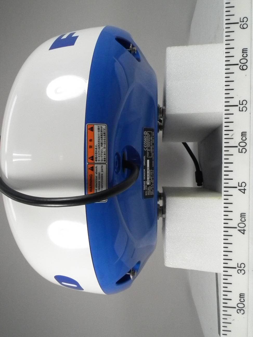
Click to zoom
Application Details
- Equipment Class
- MRD - Marine Radar
- Date of Grant
- Feb 02, 2015
- Application Purpose
- Original Equipment
- Date of Application
- Feb 02, 2015
- Equipment Note
- Transceiver for Radar Sensor DRS4DL
- Frequency Range
- 9410.00000000 - 9410.00000000
- Company
- Furuno USA Inc
- Country
- United States
Documents & Files
Document Text
Text extracted from the exhibit documents filed with the FCC. Open a document above to read the original.
Users Manual
www.furuno.com All brand and product names are trademarks, registered trademarks or service marks of their respective holders. Installation Manual RADAR SENSOR MODEL DRS4DL SAFETY INFORMATION.................................................................................................. i SYSTEM CONFIGURATION .......................................................................................... iii EQUIPMENT LIST .......................................................................................................... iv 1. INSTALLATION.......................................................................................................... 1 1.1 Installation Considerations.................................................................................................... 1 1.2 Installation of the Radar Sensor............................................................................................2 2. WIRING.......................................................................................................................6 2.1 Power Requirement .............................................................................................................. 6 2.2 Check Points After Installation ..............................................................................................6 3. MAINTENANCE, TROUBLE- SHOOTING................................................................. 8 3.1 Maintenance ......................................................................................................................... 8 3.2 Replacement of Fuse............................................................................................................ 8 3.3 Troubleshooting .................................................................................................................... 9 3.4 Replacement of Magnetron................................................................................................... 9 PACKING LIST ............................................................................................................ A-1 OUTLINE DRAWING ................................................................................................... D-1 INTERCONNECTION DIAGRAM ................................................................................ S-1 The paper used in this manual is elemental chlorine free. ・FURUNO Authorized Distributor/Dealer 9-52 Ashihara-cho, Nishinomiya, 662-8580, JAPAN A:0000 Printed in Japan All rights reserved. Z1:JAN.30, 2015 Pub. No.IME-36370-Z1 (TASU)DRS4DL 0 0 0 1 6 5 8 2 8 1 0 i SAFETY INFORMATION Read these safety instructions before installing or operating the equipment. WARNING Indicates a potentially hazardous situation which, if not avoided, can result in minor or moderate injury. Warning, CautionProhibitive Action CAUTION Mandatory Action Indicates a potentially hazardous situation which, if not avoided, can result in serious injury or death. Wear a safety belt and hard hat when working on the antenna unit. Serious injury or death can result if someone falls from the radar mast. ELECTRICAL SHOCK HAZARD Do not open the equipment. The installation does not require you to open the radar sensor. Be sure the power source is compatible with the voltage rating of the equipment. Connection of an incorrect power source can cause fire or damage the equipment. Turn off the power at the power source before beginning the installation. Fire, electrical shock or serious injury can result if the power is left on or is applied while the equipment is being installed. WARNING Do not disassemble or modify the equipment. Fire, electrical shock or serious injury can result. Use the proper fuse. Use of a wrong fuse can damage the equipment or cause fire. Do not depend one navigation device for the navigation of the vessel. For the safety of vessel and crew, the navigator must check all aids available to confirm position. SAFETY INFORMATION ii WARNING The radar antenna emits electromagnetic radio frequency (RF) energy which can be harmful, particularly to your eyes. Never look directly into the antenna aperture from a close distance while the radar is in operation or expose yourself to the transmitting antenna at a close distance. Distances at which RF radiation levels of 100, 50 and 10 W/m 2 exist are given in the table below. 100 W/m 2 10 W/m 2 50 W/m 2 N/AN/A1.1 m WARNING LABEL A warning label is attached to the sensor. Do not remove the label. If the label is missing or damaged, contact a FURUNO agent or dealer about replacement. Name: Warning Label (2) Type: 03-129-1001-3 Code No: 100-236-743 NOTICE Observe the following compass safe distance to prevent interference to a magnetic compass. It is recommended that you connect the sensor to a disconnecting device (circuit breaker, etc.) to control the power. Standard compass Steering compass 1.55 m 0.95 m iii SYSTEM CONFIGURATION Power supply 12/24 VDC RADAR SENSOR DRS4DL Multi Function Display TZTL12F/TZTL15F * TZT9/TZT14/TZTBB LAN Pre-attached power/LAN cable 1 m : Standard Supply * Software upgrade is required. Selectable power/LAN cable CP03-36400/ CP03-36410/ CP03-36420/ CP03-36430 (10/15/20/30 m) iv EQUIPMENT LIST Standard supply Optional supply NameTypeCode No.QtyRemarks Radar SensorRSB-127-104000-027-200-001 Installation MaterialsCP03-35701001-265-920-001 CP03-36400000-027-211-001Power/LAN cable 10 m CP03-36410000-027-212-001Power/LAN cable 15 m CP03-36420000-027-213-001Power/LAN cable 20 m CP03-36430000-027-214-001Power/LAN cable 30 m Spare PartsSP03-17901001-351-470-001 DocumentsIME-36370-*000-165-828-101 MDC-36370-*000-165-829-101 E32-01314-*000-178-948-101 NameTypeCode No.QtyRemarks Radome MountOP03-209001-078-350-001 1 1.INSTALLATION 1.1Installation Considerations General considerations • The radar sensor has no power switch. Therefore, it is recommended that you con- nect the sensor to a distribution switchboard with a switch for power control. Sensor placement • Install the radar sens…
Text truncated - open the document above for the full version.
Users Manual
i IMPORTANT NOTICES General How to discard this product Discard this product according to local regulations for the disposal of industrial waste. For disposal in the USA, see the homepage of the Electronics Industries Alliance (http://www.eiae.org/) for the correct method of disposal. How to discard a used battery Some FURUNO products have a battery(ies). To see if your product has a battery, see the chapter on Maintenance. Follow the instructions below if a battery is used. Tape the + and - terminals of battery before disposal to prevent fire, heat generation caused by short circuit. In the European Union The crossed-out trash can symbol indicates that all types of batteries must not be discarded in standard trash, or at a trash site. Take the used batteries to a battery collection site according to your national legislation and the Batteries Directive 2006/66/EU. In the USA The Mobius loop symbol (three chasing arrows) indicates that Ni-Cd and lead-acid rechargeable batteries must be recycled. Take the fin- ished batteries to a battery collection site according to local laws. In the other countries There are no international standards for the battery recycle symbol. The number of symbols can increase when the other countries make their own recycle symbols in the future. • This manual has been authored with simplified grammar, to meet the needs of international users. • The operator of this equipment must read and follow the descriptions in this manual. Wrong oper- ation or maintenance can cancel the warranty or cause injury. • Do not copy any part of this manual without written permission from FURUNO. • If this manual is lost or worn, contact your dealer about replacement. • The contents of this manual and equipment specifications can change without notice. • The example screens (or illustrations) shown in this manual can be different from the screens you see on your display. The screens you see depend on your system configuration and equipment settings. • Save this manual for future reference. • Any modification of the equipment (including software) by persons not authorized by FURUNO will cancel the warranty. • The microSDXC logo is a trademark of the SD Card Association. • Apple, App Store, iPhone, iPod, iPad are registered trademarks of Apple Inc, registered in the USA and other countries. • Android, Google and Google Play are registered trademarks of Google, Inc. • FLIR is a registered trademark of FLIR Systems, Inc. • OceanView is a registered trademark of Ocean Optics, Inc. • Fusion-Link is a registered trademark of FUSION Electronics, Ltd. • All brand and product names are trademarks, registered trademarks or service marks of their re- spective holders. Cd ii SAFETY INSTRUCTIONS WARNING CAUTION Warning, CautionProhibitive ActionMandatory Action WARNING The front panel of the display unit is made of glass. Handle it with care. Injury can result if the glass breaks. Please review these safety instructions before you operate the equipment. Indicates a condition that can cause death or serious injury if not avoided. Indicates a condition that can cause minor or moderate injury if not avoided. The radar antenna emits electromagnetic radio frequency (RF) energy. This energy can be dangerous to you, especially your eyes. Do not look at the radiator or near the antenna when the antenna is rotating. The distances at which RF radiation levels of 100 W/m 2 and 10 W/m 2 exist are shown in the table. Check that no person is near the radar antenna before you turn on the radar. Serious injury or death can occur if a person is hit by a rotating radar antenna. Turn off the power immediately at the switchboard if water leaks into the equipment or smoke or fire is coming from the equipment. Failure to turn off the equipment can cause fire or electrical shock. Do not open the equipment. Only qualified persons can work inside the equipment. N/A1.2 m 1.1 m 1.2 m 0.1 m 1.4 m Antenna Model Distance to 100 W/m 2 point Distance to 10 W/m 2 point DRS25A w/XN13A DRS25A w/XN12A DRS12A w/XN13A DRS12A w/XN12A DRS6A DRS4DL DRS4A DRS2D 0.2 m 0.2 m 0.5 m 0.4 m 0.4 m 2.4 m 1.9 m 5.3 m 4.4 m DRS4D N/A N/A N/A WARNING SAFETY INSTRUCTIONS iii WARNING Keep units other than the radar antenna away from rain and water. Fire or electrical shock can occur if water gets inside the equipment. Do not disassemble or modify the equipment. Fire or electrical shock can occur if the equipment is disassembled or modified. Do not operate the equipment with wet hands. Electrical shock can occur. WARNING Do not depend on one navigation device for the navigation of the vessel. Always check your position against all available aids to navigation, for the safety of vessel and crew. A radar is an excellent anti-collision aid, but remember to keep watch for possible collision conditions. Always keep a watch while underway. Do not leave any objects near the radar antenna. Fire, electrical shock or injury can result if something gets caught in the radar antenna. Use the correct fuse. A wrong fuse can cause fire or serious damage to the equipment. Do not maneuver the vessel based on the depth indication alone. Grounding can occur. The TFT LCD is constructed using the latest LCD techniques, and displays 99.99% of its pixels. The remaining 0.01% of the pixels may drop out or blink, however this is not an indication of malfunction. About the TFT LCD A safety label is attached to the display unit. Do not remove the label. If the label is missing or damaged, contact a FURUNO agent or dealer about replacement. Name: Warning Label (1) Type: 86-003-1011-3 Code No.: 100-236-233-10 Safety Labels WARNING To avoid electrical shock, do not remove cover. No user-serviceable parts inside. iv TABLE OF CONTENTS FOREWORD ....................................................................................................................x SYSTEM CONFIGURATION .........................................................................................xii 1. SYSTEM …
Text truncated - open the document above for the full version.
Users Manual
1. SYSTEM INTRODUCTION 1-11 1.7How to Edit the Display Icons The default home screen arrangement provides seven displays in configurations ac- cording to the equipment that you have in your network. If the arrangement does not meet your requirements, you can change the display icons as required. You can set a maximum of 10 display icons to show, and split a display screen up to three ways. For example, you can show the radar and sounder (fish finder) displays in a two-way split screen. The screen can be a full-screen, two-way split or three-way split. The displays avail- able depend on the display division selected and your system configuration. The table below outlines the display divisions and possible displays. 1.7.1How to add a new display icon 1. Tap the [Home] icon to show the home screen. 2. Tap the + icon. (If the icon is not shown, this means the capacity for display icons has been reached. Erase an unnecessary icon to make room. See paragraph 1.7.2.) 3. Follow the instructions below to create a display icon. Your arrangement is then opened on the screen and the home screen is updated ac- cording to your arrangement. Display divisionAvailable displays FullPlotter, weather, radar, sounder, instrument, camera Two-way splitPlotter, radar, sounder Three-way splitPlotter, radar, sounder, instrument, camera Available displays Display division Custom display areaCustom display area Drag display division Drag display division Drag display type Drag display type Tap to save icon. 1. SYSTEM INTRODUCTION 1-12 1.7.2How to edit or remove a display icon Long tap the display icon to edit to show the editing icons on the display icon. Tap the applicable editing icon, referring to the figure and description below. Change contents of display icon: Tap the icon at the upper left corner. See the il- lustration in paragraph 1.7.1 for how to set the icon. Remove display icon: Tap the icon at the upper right corner to remove the icon from the home screen. Change size of display icon: Tap the icon at the lower right corner to switch the size between large and small. (Large icons are shown on the quick page.) Long tap Remove icon Change size of icon Change contents of icon 1. SYSTEM INTRODUCTION 1-13 1.8Hidden Functions This equipment has five functions that are normally hidden from view: quick page, slide-out menu, pop-up menu, [Layers] menu, and data area (navdata). Swipe or tap the screen at the locations shown below to access the functions. A function window is automatically erased from the screen when it is not operated with the time specified with [User Interface Auto-Hide] in the [General] - [Settings] menu. You can erase the window at any time by tapping the screen. Function description The quick page selects displays. The display icons set to large size appear on the quick page. (See paragraph 1.6.2.) The slide-out menu provides quick access to often-used functions in the active dis- play. The color of the function name changes according to function status as shown below. Unavailable functions are grayed out. Swipe SwipeSwipe SwipeSwipe SwipeSwipe SwipeSwipe Tap Slide-out menu Pop-up menu Layers menu* Quick page Data area * Radar sensor connected. [Radar Overlay], [Radar Rings], [Guard Zone 1] and [Guard Zone 2] do not appear with no radar sensor connection. 1. SYSTEM INTRODUCTION 1-14 The pop-up menu provide a subset of functions that are relevant to the object or lo- cation tapped. Unavailable functions are grayed out. The [Layers] menu mainly controls the items that are displayed on the top layer of the active display. Unavailable functions are grayed out. (This menu can also be accessed from the slide-out menu (where available)). The figure below shows the [Layers] menu for the radar and weather displays. The data area shows navigation data. See the next section for details. Hidden function availability and screen division Display CameraInstrumentPlotterRadarSounderWeather LayersNoNoYesYesNoYes Pop-upYesYesYesYesYesYes Data areaYesYesYesYesYesYes Quick pageYesYesYesYesYesYes Slide-outYesYesYesYesYesYes Full screen displays and hidden function availability Layers menu for radar display Layers menu for weather display A B C A: Data area, [Layers] menu, pop-up menu, quick page B: Pop-up menu, quick page, slide-out menu C: [Layers] menu, pop-up menu, slide-out menu Three-way split screen hidden function availability 1. SYSTEM INTRODUCTION 1-15 1.9Data Area The data area at the left side of the screen shows various navigation data, in movable and editable data boxes. You can select the data to display, select format (analog or digital) and change the order of the data. Data availability depends on your system configuration. Note: The data display is also available in the two- and three-way split screens, on the left screen. Two types of data sets are available, navigation data and route data. Select the de- sired set with [DATA] or [ROUTE] at the bottom of the data area. 1.9.1How to change the order of the data Drag and drop the data boxes to change their order. Data area Data area DATA ROUTE RADAR 1. SYSTEM INTRODUCTION 1-16 1.9.2How to change the contents of a data box Tap the data box to change, and the [MODIFY NAVDATA] pop-up menu appears. Tap the data to use on the pop-up menu. 1.9.3How to add data to a data area 1. Tap any unoccupied area in the data area to display the [ADD NAVDATA] pop-up menu. Tap item to change Tap an item DATA ROUTE RADAR Cursoror DATA ROUTE RADAR 1. SYSTEM INTRODUCTION 1-17 2. Tap the data to add on the pop-up menu The added data appears at the bottom of the data display. [Cursor information] is added in the example shown below. 1.9.4How to delete a data box Tap the data box to delete, then tap [Remove] on the pop-up menu. DATA ROUTE RADAR 1. SYSTEM INTRODUCTION 1-18 1.9.5How to switch an indication between analog (graphic) and dig- ital Tap the data box for which to switch the indication, and the [MODIFY NAVDATA] pop- up menu appears. Use the [Graphic] flipswitch to…
Text truncated - open the document above for the full version.
Users Manual
1. SYSTEM INTRODUCTION 1-23 1.13Sounder (Fish Finder) Introduction The sounder display provides a picture of the echoes found by the fish finder. Echoes are scrolled across the screen from the right position to the left position. The echoes at the right position are the current echoes. These echoes can be from separate fish, a school of fish, or the bottom. Depth to the bottom is indicated always, provided the gain is set correctly. You can scroll the echoes backward. Both low and high TX frequencies are provided. (Frequencies depend on the trans- ducer connected.) The low frequency has a wide detection area, which is for general detection and understanding bottom conditions. The high frequency has a narrow beam that helps you inspect fish. The range, gain, clutter and TVG can be adjusted automatically according to your pur- pose (cruising or fishing) to let you do other tasks. Home icon Bottom echo Depth scale Fish mark * A-scope Frequency, depth 750- m 556 Slider bar * Requires appropriate transducer. Undo icon ft HF 556 1. SYSTEM INTRODUCTION 1-24 1.14Settings Menu The [Settings] menu provides the options for customizing your system. The [Settings] menu, as well as all other items on the home screen, is automatically closed, and the previous operation display restored, when no operation is detected for approx. one minute. 1. Tap the [Home] icon to go to the home screen. 2. Tap [Settings]. 3. Tap a sub menu. For example, tap the [General] sub menu. 4. Do one of the following according to the menu item: • ON/OFF flipswitch: Tap the flipswitch to switch between [ON] and [OFF]. • Slider bar, keyboard: Set level by dragging the slider, or tapping the keyboard icon () to enter the level with the numeric software keyboard. (See the next page for the appearance of the numeric keyboard.) Sub menus Menu name Preview screen shows you the result of certain selections. Back button Close button 1. SYSTEM INTRODUCTION 1-25 • Alphabet, numerical data entry: A menu item that requires entry of alphabet and/or numerical data has a keyboard icon (). Tap the keyboard icon to show the keyboard. (The keyboard displayed depends on the item selected. Some items provide only the numeric keyboard.) Enter data, then tap to con- firm. Confirm setting Switch to numerical keyboard Erase line Close window Title Delete selected character Cancel Alphabet keyboard Cursor (light blue) Shift cursor Numeric keyboard Switch to alphabet keyboard 1. SYSTEM INTRODUCTION 1-26 • Color selection: A menu item that requires selection of color shows the current color selection on the menu page. Tap the color option desired. Current selec- tion is highlighted with a light blue square. • Option selection: A menu item that requires selection of an option shows the current selection on the menu page Tap the option desired. Current selection has a checkmark. 5. Tap the close button to finish. Tap menu item. 1. SYSTEM INTRODUCTION 1-27 1.15Function Gesture The function gesture controls what occurs when you tap the screen with two fingers. Select the function as below. 1. Open the home screen, then select [Settings] - [General]. 2. Tap [Function Gesture]. 3. Tap a function among the following: [None]: Nothing happens. [Screen Capture]: Capture the screen. The message shown below appears. Tap OK to save the screen capture. The information following “BILLFISHSCREEN- SHOT” is the year, month, day, hour, minute and second the screenshot was cap- tured. [Event]: Record an event to the logbook. The selected mark is put at the position at the time the screen was tapped (see paragraph 4.2.2) [Home]: Open the home screen (see section 1.6) [Settings]: Open the [Settings] menu (see section 1.14). [List]: Open the lists menu (see section 1.14 and section 4.8). Event Home Settings List Tide Fusion Fusion Bar 1. SYSTEM INTRODUCTION 1-28 [Tide]: Open the tide graph (see section 1.14 and paragraph 3.2.4). [Fusion]:Show full FUSION display. [Fusion Bar]: Show the FUSION bar. 4. Tap the close button to finish. 1.16Language The default interface language is English (United States). To select a different lan- guage, do as follows: 1. Open the home screen, then tap [Settings] - [General]. 2. Tap [Language]. 3. Tap the language to use. The message "APPLICATION HAS TO RESTART NOW! DO YOU WANT TO RESTART APPLICATION?" appears. 4. Tap [OK] then the equipment restarts. 1. SYSTEM INTRODUCTION 1-29 1.17Man Overboard (MOB) The MOB function is used to mark the location of man overboard. At the moment the MOB function is activated, the MOB mark is put at the current position, on the plotter and radar displays. How to mark the MOB position Tap [MOB] on the home screen. The plotter display opens, the MOB mark () is at the location at the moment MOB was activated, and the MOB location is automatically set as destination. At the moment of activation the following occurs. • The message"MOB" flashes in the status bar, yellow characters on a red back- ground. The aural alarm sounds if it is enabled. Tap the status bar to stop the flash- ing and silence the aural alarm. • The MOB mark is highlighted. • A yellow line connects between the MOB mark and current location. This line shows the straightest course between own ship and the MOB mark. MOB information Tap a MOB mark to display the name, comment and depth (plotter display only). How to delete a MOB mark Inactive MOB mark: Tap a MOB mark to display the pop-up menu. Tap [Delete]. Active MOB mark: Before you erase an active MOB mark, you must stop navigation. Tap the active MOB mark to display the pop-up menu then select [Stop Nav]. Tap the MOB mark to display the pop-up menu, then tap [Delete]. MOB mark on the plotter display MOB mark on the radar display 1. SYSTEM INTRODUCTION 1-30 1.18Wireless LAN Settings You can connect to the internet with the wireless LAN signal to download weather in- formation (see chapter 11) and to connect to an iPhone, iPod, iPad, or Android ™ de- vice. To download weather information, connect th…
Text truncated - open the document above for the full version.
Users Manual
2. PLOTTER 2-13 2.11.1XTE alarm The XTE alarm tells you when your ship goes off course by more than the limit set (XTE alarm boundaries). 1. Turn on [XTE Alarm] in the [Alarm] menu. 2. Tap [XTE Alarm Value] to display the software keyboard. 3. Set the value, then tap . 4. Tap the close button at the top of the screen to close the menu. 2.11.2Depth alarm The depth alarm tells you when the depth to the bottom is shallower than the value you set. Requires depth data. 1. Turn on [Depth Alarm] in the [Alarm] menu. 2. Tap [Depth Alarm Value] to display the software keyboard. 3. Set the value, then tap . 4. Tap the close button to finish. 2.11.3SST alarm The sea surface temperature alarms tells you when the sea surface temperature is over, under, within, or out of range of the temperature you set. Requires a temperature sensor. 1. Tap [Sea Surface Temperature Alarm] on the [Alarm] menu. 2. Tap [Over], [Under], [Within], [Out of] or [Shear]. Follow the appropriate procedure below. Alarm setting Go to point Intended course :Alarm area Starting point 2. PLOTTER 2-14 [Over] or [Under] The [Over] or [Under] alarm sounds when the temperature is over or under the set value, respectively. 1) Tap [Temperature Alarm Value] to display the software keyboard. 2) Set the value, then tap . Go to step 3. [Within] or [Out of] The [Within] or [Out of] alarm sounds when the temperature is within or out of the temperature range set, respectively. 1) Tap [Temperature Alarm Minimum Value] to display the software keyboard. 2) Set the minimum value, then tap . 3) Tap [Temperature Alarm Maximum Value] to display the software keyboard. 4) Set the minimum value, then tap . Go to step 3. [Shear] The shear alarm sounds when the temperature exceeds the alarm setting for 10 seconds. 1) Tap [Temp. Shear Alarm Value] to display the software keyboard. 2) Set the value, then tap . Go to step 3. 3. Tap the close button to finish. 2.11.4Speed alarm The speed alarm tells you when the speed of your ship is over or under the limit set. Set the value at [Speed Alarm Value]. 1. Tap [Speed Alarm] on the [Alarm] menu. 2. Tap [Over] or [Under]. 3. Tap [Speed Alarm Value] to display the software keyboard. 4. Set the value for [Over] or [Under] then tap . 5. Tap the close button to finish. 2. PLOTTER 2-15 2.11.5Anchor watch alarm The anchor watch alarm tells you that your ship has moved a distance greater than the set value when the ship must not be moving. 1. Turn on [Anchor Watch Alarm] in the [Alarm] menu. 2. Tap [Anchor Watch Alarm Value] to display the software keyboard. 3. Set the value, then tap . 4. Tap the close button to finish. 2.11.6Other Alarm menu items The followings are the alarm menu items not previously mentioned. [Hardware Alarm]: This alarm alerts you when something is wrong with the hardware. [Notification Sound]: Activate or deactivate the notification sound (for "Waypoint Crossing" (see section 5.8), "End of Route" (section 4.11) or fish finder alarms (section 7.10)). [Alarm Sound]: Disable or enable the buzzer. [Sound Alarm Until Acknowledged]: Turn this item on to sound the aural alarm until an alarm is acknowledged (see paragraph 2.11.7). [Save Log File]: Save alert list to SD card. [Reset Default Settings]: Select this menu item to restore default settings for the [Alarm] menu. Your ship's position where you start the anchor watch alarm. Alarm setting : Alarm area 2. PLOTTER 2-16 2.11.7How to show the Alarms list When an alarm is violated, you can see the name of the offending alarm on the [Alarms] list. The list stores both warning and system messages. Open the home screen, then tap [Lists] followed by [Alarms]. Active alarms are flashing. Tap an active alarm to acknowledge it and stop the f lashing. Acknowledged alarms appear in the [HISTORIC] section. Tap the close button to close the list. 2.12Track The track (or movement) of your ship is plotted on the screen with position data. Your track lets you see how your ship has moved. The track is saved to the internal memory if the track is active. A line runs between each track point. The internal memory stores a maximum of 30,000 track points. Your track remains on the screen when the power is turned off. You can delete the track that you do not need from the home screen. The saved track can be shown on the screen, and you can make a route with the saved track. 2.12.1How to start, stop recording the track Start recording Open the slide-out menu or tap the boat icon, then turn [Track] on. Stop recording Method 1: Tap the track, then tap [Stop Track]. Method 2: Open the slide-out menu or tap the boat icon. Turn [Track] off. 2.12.2How to show or hide the track display Open the [Layers] menu and turn [Tracks] on or off. Sea Surface Temperature Alarm Depth Alarm Track 2. PLOTTER 2-17 2.12.3Track interval In drawing the track, the position of your ship is stored into the memory of this unit at an interval of time. A shorter interval provides better reconstruction of the track, but the storage time of the track is reduced. 1. Open the home screen, then tap [Settings] - [Ship & Track]. 2. Tap [Track Interval]. 3. Tap a time interval. 4. Tap the close button at the top of the screen to close the menu. 2.12.4Track color Track can be displayed in a single color or multiple colors. For multiple colors, you can display the track according to the conditions shown below. • SST (Sea Surface Temperature) • Speed • Depth • Bottom sediment Note: The “bottom sediment” method requires a bottom discrimination capable trans- ducer, bottom discrimination sounder BBDS1, or network sounder DFF1-UHD. From the home screen 1. Open the home screen, then tap [Settings] - [Ship & Track]. 2. Tap [Track Color]. 3. Tap [Fixed] or [Variable]. Tap “>” to go back one layer. For [Fixed], go to the next step. For [Variable], go to step 5. 2. PLOTTER 2-18 4. Tap [Fixed Color Setup] then tap a color. Go to step 10. 5. Tap [Variable Color] then tap an option. [Depth]: Change the color of the track …
Text truncated - open the document above for the full version.
Contact Information
Applicant
Bill Haynes(Deep Sea Product Manager)
Test Firm
Labotech International Co., Ltd.Yoshihiro Ishii
Technical Specifications
| # | Rule Parts | Frequency Range | Power Output | Emission | Tolerance |
|---|---|---|---|---|---|
| 1 | 80 | 9.41 GHz - 9.41 GHz | 4000 W | 55M9P0N | 30000.0000000000 Hz |
Other Applications from Furuno USA Inc
ADB-9ZWRTR137
Feb 18, 2026Transceiver unit for the radar sensor
Equipment Class
MRD - Marine RadarADB9ZWRTR136
Jul 01, 2024Transceiver unit for the radar sensor
Equipment Class
MRD - Marine Radar
ADB9ZWRTR128
Apr 06, 2022Transceiver unit for the radar sensor
Equipment Class
MRD - Marine Radar
ADB9ZWRTR133
Sep 26, 2021Transceiver unit for the radar sensor
Equipment Class
MRD - Marine Radar
ADB9ZWRTR129
May 23, 2021Transceiver unit for the radar sensor
Equipment Class
MRD - Marine Radar