ADB9ZWRTR107Transceiver for Radar model FAR-3230S/3330S
Furuno USA Inc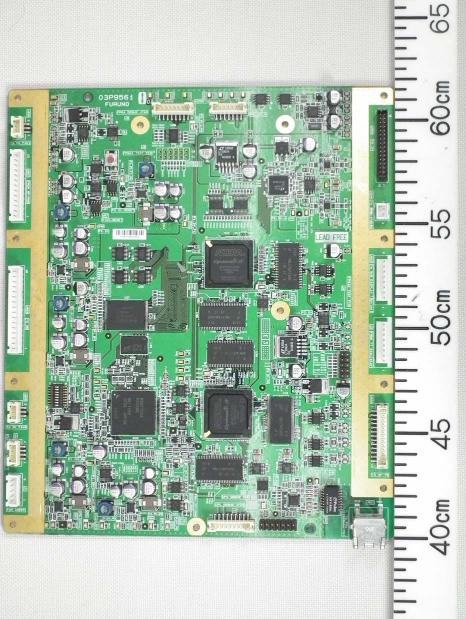
Click to zoom
Application Details
- Equipment Class
- MRD - Marine Radar
- Date of Grant
- Jan 09, 2015
- Application Purpose
- Original Equipment
- Date of Application
- Jan 09, 2015
- Equipment Note
- Transceiver for Radar model FAR-3230S/3330S
- Frequency Range
- 3050.00000000 - 3050.00000000
- Company
- Furuno USA Inc
- Country
- United States
Documents & Files
Document Text
Text extracted from the exhibit documents filed with the FCC. Open a document above to read the original.
Users Manual
OPERATOR'S MANUAL www.furuno.com CHART RADAR FAR-3210 FAR-3220 FAR-3230S FAR-3230S-SSD FAR-3310 FAR-3320 FAR-3330S FAR-3330S-SSD FAR-3320W FAR-3330SW FAR-3210-BB FAR-3220-BB FAR-3230S-BB FAR-3230S-SSD-BB FAR-3220W-BB FAR-3230SW-BB Model (Product Name: MARINE RADAR) The paper used in this manual is elemental chlorine free. ・FURUNO Authorized Distributor/Dealer 9-52 Ashihara-cho, Nishinomiya, 662-8580, JAPAN A:APR2014 . Printed in Japan All rights reserved. B2:DEC.15, 2014 Pub. No. OME-36160-B2 ( YOTA ) FAR-3000SERIES 0 0 0 1 7 8 0 2 7 1 1 i IMPORTANT NOTICES General How to discard this product Discard this product according to local regulations for the disposal of industrial waste. For disposal in the USA, see the homepage of the Electronics Industries Alliance (http://www.eiae.org/) for the correct method of disposal. How to discard a used battery Some FURUNO products have a battery(ies). To see if your product has a battery, see the chapter on Maintenance. Follow the instructions below if a battery is used. Tape the + and - terminals of battery before disposal to prevent fire, heat generation caused by short circuit. In the European Union The crossed-out trash can symbol indicates that all types of batteries must not be discarded in standard trash, or at a trash site. Take the used batteries to a battery collection site according to your national legislation and the Batteries Directive 2006/66/EU. In the USA The Mobius loop symbol (three chasing arrows) indicates that Ni-Cd and lead-acid rechargeable batteries must be recycled. Take the used batteries to a battery collection site according to local laws. In the other countries There are no international standards for the battery recycle symbol. The number of symbols can increase when the other countries make their own recycle symbols in the future. • This manual has been authored with simplified grammar, to meet the needs of international users. • The operator of this equipment must read and follow the descriptions in this manual. Wrong oper- ation or maintenance can cancel the warranty or cause injury. • Do not copy any part of this manual without written permission from FURUNO. • If this manual is lost or worn, contact your dealer about replacement. • The contents of this manual and equipment specifications can change without notice. • The example screens (or illustrations) shown in this manual can be different from the screens you see on your display. The screens you see depend on your system configuration and equipment settings. • Save this manual for future reference. • Any modification of the equipment (including software) by persons not authorized by FURUNO will cancel the warranty. • All brand and product names are trademarks, registered trademarks or service marks of their re- spective holders. • “C-MAP” means “C-MAP by Jeppesen” in this manual. • Windows is a registered trademark of the Microsoft Corporation of the USA and other countries. Cd Ni-CdPb ii SAFETY INSTRUCTIONS The operator must read the safety instructions before attempting to operate the equipment. The radar antenna emits electromagnetic radio frequency (RF) energy that can be harmful, particularly to your eyes. Never look directly into the antenna aperture from a close distance while the radar is in operation or expose yourself to the transmitting antenna at a close distance. Distances at which RF radiation level of 100, 50 and 10 W/m 2 are given in the table below. Indicates a potentially hazardous situation which, if not avoided, could result in death or serious injury. Indicates a potentially hazardous situation which, if not avoided, could result in minor or moderate injury. 100W/m 2 Radar model FAR-3220/ FAR-3320/ FAR-3220-BB FAR-3210/ FAR-3310/ FAR-3210-BB FAR-3230S/ FAR-3330S/ FAR-3230S-BB FAR-3330SW/ FAR-3230SW-BB FAR-3320W/ FAR-3220W-BB TransceiverMagnetronAntenna 10W/m 2 50W/m 2 Warning, CautionProhibitive Action Mandatory Action Radio Frequency Radiation Hazard WARNING CAUTION WARNING RTR-105 FNE1201 XN12CF XN20CF XN24CF RTR-106 MG5436 XN12CF XN20CF XN24CF RTR-108 MG5436 XN20CF XN24CF RTR-107 MG5223F SN36CF RTR-109 MG5223F SN36CF Magnetron radar 100W/m 2 Radar model FAR-3230S-SSD/ FAR-3330S-SSD/ FAR-3230S-SSD-BB TransceiverAntenna 10W/m 2 50W/m 2 RTR-111 SN36CF Solid state radar N/A N/A N/A 1.0 m 0.5 m4.6 m 0.6 m 1.4 m4.4 m 0.4 m 0.9 m3.0 m 0.3 m 0.6 m2.5 m 1.3 m 2.7 m9.5 m 1.0 m 1.7 m6.8 m 0.7 m 1.3 m5.5 m N/A 0.26 m2.3 m 0.5 m 1.2 m5.5 m 0.3 m 0.9 m4.0 m SAFETY INSTRUCTIONS iii WARNING Do not open the equipment. The equipment uses high voltage that can cause electrical shock. Refer any repair work to a qualified technician. Before turning on the radar, be sure no one is near the antenna. Prevent the potential risk of being struck by the rotating antenna, which can result in serious injury or death. If water leaks into the equipment or something is dropped into the equipment, immediately turn off the power at the switchboard. Fire or electrical shock can result. If the equipment is giving off smoke or fire, immediately turn off the power at the switchboard. Fire or electrical shock can result. If you feel the equipment is acting abnormally or giving off strange noises, immediately turn off the power at the switchboard and contact a FURUNO service techni- cian. Do not disassemble or modify the equipment. Fire, electrical shock or serious injury can result. Make sure no rain or water splash leaks into the equipment. Fire or electrical shock can result if water leaks into the equipment. Do not place liquid-filled containers on or near the equipment. Fire or electrical shock can result if a liquid spills into the equipment. Do not operate the equipment with wet hands. Electrical shock can result. Keep objects away from the open- type antenna unit, so as not to impede rotation of the antenna. Fire, electrical shock or serious injury can result. Use the proper fuse. Use of the wrong fuse can cause fire or damage the equipment. The TT function is a valuable…
Text truncated - open the document above for the full version.
Users Manual
www.furuno.com All brand and product names are trademarks, registered trademarks or service marks of their respective holders. Installation Manual CHART RADAR Model FAR-3230S(-BB)/FAR-3330S (Product Name: MARINE RADAR) SAFETY INSTRUCTIONS ................................................................................................ i SYSTEM CONFIGURATION .......................................................................................... iii EQUIPMENT LISTS........................................................................................................ vi 1. INSTALLATION....................................................................................................... 1-1 1.1 Antenna Unit ......................................................................................................................1-1 1.2 Monitor Unit........................................................................................................................1-8 1.3 Radar Control Unit, Trackball Control Unit.........................................................................1-8 1.4 Power Supply Unit (PSU-014/PSU-015)..........................................................................1-11 1.5 Processor Unit .................................................................................................................1-12 1.6 Sensor Adapter MC-3000S/3010A/3020D/3030D (option) ..............................................1-13 1.7 Intelligent Hub HUB-3000 (option) ...................................................................................1-14 1.8 Switching Hub HUB-100 (option) .....................................................................................1-16 2. WIRING.................................................................................................................... 2-1 2.1 Overview ............................................................................................................................2-1 2.2 Antenna Unit ......................................................................................................................2-3 2.3 Processor Unit .................................................................................................................2-10 2.4 Power Supply Unit ...........................................................................................................2-21 2.5 Monitor Unit......................................................................................................................2-25 2.6 Sensor Adapters (option) .................................................................................................2-26 2.7 LAN Signal Converter Kit (option)....................................................................................2-43 2.8 Intelligent Hub HUB-3000 (option) ...................................................................................2-47 2.9 How to Extend the Control Unit Cable (option) ................................................................2-48 3. SETTINGS AND ADJUSTMENTS .......................................................................... 3-1 3.1 How to Access the Radar Installation Menu ......................................................................3-1 3.2 How to Align the Heading ..................................................................................................3-1 3.3 How to Adjust the Sweep Timing .......................................................................................3-2 3.4 How to Suppress Main Bang .............................................................................................3-3 3.5 Dual Radar Display ............................................................................................................3-3 3.6 Other Settings ....................................................................................................................3-6 4. INPUT/OUTPUT DATA............................................................................................ 4-1 4.1 Processor Unit ...................................................................................................................4-1 4.2 IEC 61162 Sentences ........................................................................................................4-2 APPENDIX 1 JIS CABLE GUIDE ............................................................................. AP-1 APPENDIX 2 ROD TERMINALS .............................................................................. AP-2 APPENDIX 3 DIGITAL INTERFACE ........................................................................ AP-7 PACKING LISTS ......................................................................................................... A-1 OUTLINE DRAWINGS ................................................................................................ D-1 INTERCONNECTION DIAGRAMS.............................................................................. S-1 The paper used in this manual is elemental chlorine free. ・FURUNO Authorized Distributor/Dealer 9-52 Ashihara-cho, Nishinomiya, 662-8580, JAPAN A:APR2014 . Printed in Japan All rights reserved. C:OCT.15, 2014 Pub. No. IME-36180-C ( AKMU ) FAR-3230S 0 0 0 1 7 8 0 3 3 1 2 i SAFETY INSTRUCTIONS The operator and installer must read the applicable safety instructions before attempting to install or operate the equipment. DANGER Indicates a potentially hazardous situation which, if not avoided, will result in death or serious injury. Indicates a potentially hazardous situation which, if not avoided, could result in death or serious injury. CAUTION Indicates a potentially hazardous situation which, if not avoided, can result in minor or moderate injury. Warning, Caution Prohibitive Action Mandatory Action DANGER Wear a safety belt and hard hat when working on the antenna unit. Serious injury or death can result if someone falls from the radar antenna mast. WARNING Radio Frequency Radiation Hazard The radar an…
Text truncated - open the document above for the full version.
Users Manual
2. WIRING 2-8 8) Fasten the two heater elements to the chassis. Fasten the base of the heater with two M5 screws (supplied) coated with marine sealant supplied. Fasten the installation materials to each of the cover bolts. 9) Attach the supplied earth label over the earth label attached near the ground- ing terminal. Note: If it is necessary to open the front cover after installing the DE- ICER kit, remove the power cable from the locking wire saddle in the right figure then detach the cover slowly to prevent damage to the heater. 14. Re-mount the RF unit then reconnect the connectors for the motor (J803, J840 and J804), the four bolts (see step 4) and the coaxial cable (see step 3). The torque must be 27.5 N•m. 15. Pass the LAN cable of the antenna cable from the cable entrance through two locking wire saddles to the LAN port at the bottom of the RF unit (J821). 16. Attach appropriate WAGO connector (supplied) to both the antenna cable and the cable for the sub monitor. Connect the antenna cable and the cable for the sub monitor to the RF-TB Board as shown below. A terminal opener is provided on the RF-TB Board. Cover BoltCover Bolt M5 screwM5 screw Fixing Shaft Fixing Shaft SD Heater Fixing Plate SD Heater Fixing Plate M5 screw coated with marine sealantM5 screw coated with marine sealant Grounding terminalGrounding terminal Earth label Remove the power cable from the locking wire saddle to open the front cover. Remove the power cable from the locking wire saddle to open the front cover. Locking wire saddles Locking wire saddles LAN portLAN port 2. WIRING 2-9 • Antenna cable: Power : TB801 on RF-TB Board (03P9570) LAN : J821 on RF-TB board Shields : For the power cable, screw on RF-TB Board (03P9570). For the LAN cable, screw near the LAN slot. For the antenna cable RW-9600, connect the crimp-on lug (that binds unused wires) together with the shield of the power cable. • Cable for sub monitor: Remove (or Loosen) four bolts shown in the right figure to remove the RF-TB board from the RF unit. Signal : TB803 on RF-TB board Coax. cable : TB804 on RF-TB board Shield : Screw on chassis. 17. Reconnect the performance monitor connector (J807), see step 2 on page 2-5. 18. Check that the gasket on the rear cover is seated properly, then close the covers. The torque must be 21.0 N•m. Wire How to connect wires to WAGO connector Press downward. Terminal opener WAGO connector Twist <Procedure> 1. Twist the cores. 2. Press the terminal opener downward. 3. Insert the wire to hole. 4. Remove the terminal opener. 5. Pull the wire to confirm that it is secure. 1367891124510 BRNREDORG YEL GRN BLU PPL WHT Pin Color TB801TB801 Grounding point for Power cable Grounding point for Power cable Grounding point for LAN cable Grounding point for LAN cable LoosenLoosen RemoveRemove TB804TB804 TB803TB803 13678911 12 13 14 15 1624510 BRNRED ORG YELBLKWHT Pin Color How to fasten the coaxial cable NOTICE Do not use crimp-on lug, to prevent contact resistance from increasing. Fasten conductor with screw.Fasten conductor with screw. Fasten shield with clamp.Fasten shield with clamp. Pass through the locking wire saddle. Pass through the locking wire saddle. 2. WIRING 2-10 2.3Processor Unit Note: The interface ports approved for interconnecting navigation equipment are shown in the figure below. For details, see paragraph 2.3.3 "How to select the serial input/output format". 2.3.1How to connect cables to terminals in the processor unit Use screws (M3×6, supplied) to attach the wiring plate 1 and wiring plate 2 to the pro- cessor unit. Connect the cables shown below to the connectors at the front of the pro- cessor unit. Bind cables to the appropriate fixing metal with the cable ties (supplied). For the cables from the monitor unit (type: DVI-D/D SLINK5M/10M* (*: MU-190 only), DSUB9P-X2-L5/10M) and ground wire, connect them to the processor unit directly (without fixing to a wiring plate). Tighten the fixing screws on these connectors to pre- vent disconnection from the processor unit. Note: Connect the cables so that they do not interfere with the opening or closing of the DVD tray. J5J5J5 J11J11J11 J4J4J4 J3J3J3 J8J8J8 J9J9J9 J10J10J10 J6J6J6 J7J7J7 J12J12J12 J13J13J13 J14J14J14 J3, J4 For IEC 61162-2 or IEC 61162-1 J5, J6, J7, J8, J9, J10 For IEC 61162-1 Top view of EC-3000 OK UP Desktop or Bulkhead (Sideway slot) Hanging or Bulkhead (Vertical slot) 2. WIRING 2-11 Cables connected at wiring plate 1 assy • USB cables from the control units • Printer cable • LAN cable (type: DTI-C5E350 VCV) from the HUB-3000 • LAN cable (type: FR-FTPC-CY) from the HUB-100/MC-3000S Cables connected at the wiring plate 2 • Power cable (Type: IEC60320-C13-L5M) • LAN cable to the LAN3 port Wiring plate 2 assy Wiring plate 1 Slide the plate toward the unit to hide LED and switches. MU-190/231 (DVI1: DVI-D/D S-LINK cable, COM1: DSUB9P-X2-L cable) COM1 DVI3 USB1 RCU-025/026 (TS-20-071-1 cable) USB2/3 Optional control unit RCU-024/025/026 (TS-20-071-1 cable) HUB-3000 (DTI-C5E350 VCV cable) LAN1 LAN2 HUB-100/MC-3000S (FR-FTPC-CY cable, within 50m) DVI1 COM2 Cable clamp Ground wire (IV-2sq., local supply) Power cable (IEC60320-C13- L5M cable) USB4 For USB printer LAN3 MOD-Z072-005+ DVI2 MU-190/231 (DVI2: DVI-D/D S-LINK cable or DVI-BNCX5-L2000 cable) VDR (DVI3: BNCX5-L2000 cable) (COM2: DSUB9P-X2-L cable) 2. WIRING 2-12 How to fabricate the LAN cable Fabricate the LAN cable (FR-FTPC-CY, DTI-C5E350 VCV), as shown below. (Wrap both edges of the armor with vinyl tape.) Make sure the shield of the cable contacts the shell of the modular plug. Note: For a locally supplied LAN cable, expose the armor and clamp the armor with the cable clamp. Wrap vinyl tape. (width: 20 mm) Cable jacket Armor Outer vinyl sheath Inner vinyl sheath 55 30 Using special crimping tool MPT5-8 (PANDUIT CORP.), crimp the modular plug. Finally check the plug visually. Expose inner vinyl sheath. Remove the outer sheath by approx 25 mm. Be careful not to damage inner shield and cor…
Text truncated - open the document above for the full version.
Users Manual
2. WIRING 2-33 2.6.2MC-3010A/3020D/3030D • MC-3010A: Inputs analog signal. To use MC-3010A as current input, connect short pins to each terminals. • MC-3020D: Inputs digital signal (8ch contact input). Contact or voltage input is se- lectable (contact input requires short pins). • MC-3030D: Outputs digital signal (8ch, normal open/close). Fabrications MC1.5-W-L600/1000/2000/3000 cable (Input) Vinyl tape (width: 10) Vinyl tape (width: 10) Vinyl tape (width: 10) Shield (fold back) Shield (fold back) Shield (fold back) Core: 6Core: 6Core: 6 303030 120120120 TTYCSLA-1 (MC-3010A) Vinyl tape (width: 10) Vinyl tape (width: 10) Vinyl tape (width: 10) 808080 606060 606060 Pass drain wire through shrink tubing (local supply), then attach crimp-on lug (pre-attached in unit). Core: 6Core: 6Core: 6 MPYC-12 cable (MC-3030D) MC1.5-W-L600/1000/2000/3000 cable (Output) Vinyl tape (width: 10) Vinyl tape (width: 10) Vinyl tape (width: 10) Shield (fold back) Shield (fold back) Shield (fold back) Core: 6Core: 6Core: 6 303030 100100100 80 or more 80 or more 80 or more Not used: Cut with 50, and wind tape to insulate. Not used: Cut with 50, and wind tape to insulate. Not used: Cut with 50, and wind tape to insulate. 125125125 858585 Core: 6Core: 6Core: 6 MPYC-12 cable (MC-3020D) Not used: Cut with 50, and wind tape to insulate. Not used: Cut with 50, and wind tape to insulate. Not used: Cut with 50, and wind tape to insulate. TTYCS-1 (MC-3010A) 80 or more 80 or more 80 or more 135135135 959595 Core: 6Core: 6Core: 6 Vinyl tape (width: 10) Vinyl tape (width: 10) Vinyl tape (width: 10) 80 or more 80 or more 80 or more Shield (fold back) Shield (fold back) Shield (fold back) 303030 606060 Core: 6Core: 6Core: 6 2. WIRING 2-34 Connection MC-3020D/3030D J1J1J1 J2J2J2 J4J4J4 J5J5J5 J3J3J3 MC1.5-W-L cableMC1.5-W-L cableMC1.5-W-L cable TTYCS-1/ TTYCSLA-1 TTYCS-1/ TTYCSLA-1 TTYCS-1/ TTYCSLA-1 IV-1.25sq. (Local supply)IV-1.25sq. (Local supply)IV-1.25sq. (Local supply) Note: The cable shield must lie in the cable clamp. For TTYCSLA cables, pass the drain wire through shrink tubing, then attach these crimp-on lugs and screws to connect drain wires to chassis. J1J1 J2J2 J4J4 J5J5 J3J3 MC1.5-W-L cableMC1.5-W-L cable MPYC-12MPYC-12 IV-1.25sq. (Local supply)IV-1.25sq. (Local supply) J6J6 Note: The cable shield must lie in the cable clamp. 2. WIRING 2-35 Input method (MC-3010A only) Select the method of the analog data input, power voltage or power current. Note 1: The input must not exceed the range of the input voltage, to prevent malfunc- tion. • Setting for voltage input: -10V to +10V or 0 to 10V (depending on the setting) • Setting for contact input: Voltage 4mA to 20mA. Note 2: When changing the input method, turn off the MC-3010A and on again to put change in effect. Power voltage: Input the amount of power voltage change to the operational ampli- fier. Power current: Pass the power current to the shunt resistor, 1kΩ/parallel (com- bined resistance: 500Ω) to input the amount of voltage change at the both ends of the resistor to the operational amplifier. Connector J3 Pin # Signal nameIn/OutDescriptionPower voltagePower current 1AN1_INInAnalog 1 inputTTYCS(LA)-1 2AN1_GND-Analog 1 GND 3CURR1_JP1-Analog 1 input, power current/ voltage setting jumper 1 Pin #3-#4: open Pin #3-#4: short 4CURR1_JP2-Analog 1 input, power current/ voltage setting jumper 2 AN-IN AN-GND CURR-JP1 AN +15V AN GND AN - 15V Opeamp Vin InGnd +V S1 -VS1 +V S2 -VS2 OutGnd +1 5V GND -15V Voltage source Load Jumper: open 1kΩ 1% 0.5W×2 CURR-JP2 AN- IN AN- GND CURR- JP 1 CURR- JP 2 AN +15V AN GND AN - 15V Opeamp Vin InGnd +V S1 -VS1 +V S2 -VS2 OutGnd +1 5V GND -15V Current source Load Jumper short 1kΩ 1% 0.5W×2 Use NH connector and AWG24 cable. 2. WIRING 2-36 Connector J4 Connector J5 How to set ACK input (MC-3020D) Use the connectors J3 to J6 to set the ACK input for ACK1 to ACK8 as shown below. Note: The input must not exceed the range of the input voltage, to prevent malfunc- tion. • Setting for voltage input: 21.6V to 31.2V • Setting for contact input: Voltage cannot be input (contact signal only). Input circuit for voltage input Input circuit for contact input Pin # Signal nameIn/OutDescriptionPower voltagePower current 1AN2_INInAnalog 2 inputTTYCS(LA)-1 2AN2_GND-Analog 2 GND 3CURR2_JP1-Analog 2 input, power current/ voltage setting jumper 1 Pin #3-#4: open Pin #3-#4: short 4CURR2_JP2-Analog 2 input, power current/ voltage setting jumper 1 Pin # Signal nameIn/OutDescriptionPower voltagePower current 1AN3_INInAnalog 3 inputTTYCS(LA)-1 2AN3_GND-Analog 3 GND 3CURR3_JP1-Analog 3 input, power current/ voltage setting jumper 1 Pin #3-#4: open Pin #3-#4: short 4CURR3_JP2-Analog 3 input, power current/ voltage setting jumper 1 DC12V_OUT DIGI_IN1 DIGI_RTN1 GND(DC12V) GND 5V DC voltage input (21.6V to 31.2V) + - 12V GND 470Ω/ 0.5W 2.2kΩ / 1W Register Photocoupler circuit MC-DIN Board GND 5V 12V GND 470Ω/ 0.5W 2.2kΩ / 1W Contact input DC12V_OUT DIGI_INx DIGI_RTNx GND(DC12V) Register Photocoupler circuit MC-DIN Board Use NH connector and AWG24 wire. 2. WIRING 2-37 Connector J3 Connector J4 Connector J5 Pin # Signal nameIn/OutRemarks ACK1 contact ACK1 voltage ACK2 contact ACK2 voltage 1DC12V_OUTOutACK1 InPin #1-#2: short No connec- tion Depending on ACK1 input 2DIGI_IN1InMPYC-12 3DIGI_RTN1OutMPYC-12 4GND (DC12V) InNo connec- tion 5DC12V_OUTOutACK2 In Depending on ACK2 input Pin #1-#2: short No connec- tion 6DIGI_IN2InMPYC-12 7DIGI_RTN2OutMPYC-12 8GND (DC12V) InNO con- nection Pin #Signal nameIn/Out Remarks ACK1 contact ACK1 voltage ACK2 contact ACK2 voltage 1DC12V_OUTOutACK3 InPin #1-#2: short No connection Depending on ACK3 in- put 2DIGI_IN3InMPYC-12 3DIGI_RTN3OutMPYC-12 4GND (DC12V) InNo connection 5DC12V_OUTOutACK4 In Depending on ACK4 input Pin #1-#2: short No con- nection 6DIGI_IN4InMPYC-12 7DIGI_RTN4OutMPYC-12 8GND (DC12V) InNo con- nection Pin #Signal nameIn/OutRemarks ACK1 contact ACK voltage ACK2 contact ACK2 voltage 1DC12V_OUTOutACK5 InPin #1-#2: short No…
Text truncated - open the document above for the full version.
Users Manual
APPENDIX 3 DIGITAL INTERFACE AP-12 VTG - Course over ground and ground speed ZDA - Time and date Output sentences For ACK, ALR and HBT see input sentences. ABM - UAIS Addressed binary and safety related message ALC - Cyclic alert list $**VTG,x.x,T,x.x,M,x.x,N,x.x,K,a,*hh <CR><LF> 1 2 3 4 5 6 7 8 9 1. Course over ground, degrees (0.00 - 360.00) 2. T=True (fixed) 3. Course over ground, degrees (No use) 4. M=Magnetic (No Use) 5. Speed over ground, knots (0.00-99.94) 6. N=Knots (fixed) 7. Speed over ground (0.00-99.94) 8. K=km/h (fixed) 9. Mode indicator ( A=Autonomous, D=Differential E=Estimated (dead reckoning) M=Manual input S=Simulator P=Precision) $**ZDA,hhmmss.ss,xx,xx,xxxx,xx,xx<CR><LF> 1 2 3 4 5 6 1. UTC (000000.00 - 235960.99) 2. Day (01 - 31) 3. Month (01 -12) 4. Year (UTC, 1970 - 2037) 5. Local zone, hours (No use) 6. Loca zone, minutes (No use) !**ABM,x,x,x,xxxxxxxxx,x,x.x,s--s,x,*hh<CR><LF> 1 2 3 4 5 6 7 8 1. Total number of sentences needed to transfer the message (1 - 9) 2. Message sentence number (1 - 9) 3. Message sequence identifier (0 - 3) 4. The MMSI of destination AIS unit for the ITU-R M.1371 message (9 digits) 5. AIS channel for broadcast of the radio message (0 - 3) 6. VDL message number (6 or 12), see ITU-R M.1371 7. Encapsulated data (1 - 63 bytes) 8. Number of fill-bits (0 - 5) $**ALC,xx,xx,xx,x.x, aaa,x.x,x.x,x.x,’’’’’’’’’,*hh<CR><LF> 1 2 3 4 5 6 7 8 9 1. Total number of sentences this message (01 to 99) 2. Sentence number (01 to 99) 3. Sequential message identifier (00 to 99) 4. Number of alert entries (0 to 3) 5. Manufacturer mnemonic code (FEC, null) 6. Alert identifier (999 or 10001 to 10999) 7. Alert instance (null) 8. Revision counter (1 to 99) 9. Additional alert entries (see Note) Note: Alert entry 0 - n: Each alert entry consists of - Manufacturer Identifier (see ALF Manufactuer - Alert Identifier (see ALF Alert identifier) - Alert instance (see ALF instance) - Revision counter (see ALF revision counter) Each entry identifies a certain alert with a certain state. It is not allowed that an alert entry is split between two ALC sentences. Alert entry 1 See Note APPENDIX 3 DIGITAL INTERFACE AP-13 ALF - Alert sentence ARC - Alert command refused BBM - UAIS broadcast binary message EVE - General event message $**ALF,x,x,x,hhmmss.ss,a,a,a,aaa,x.x,x.x,x.x,x,c--c,*hh<CR><LF> 1 2 3 4 5 6 7 8 9 10 11 12 13 1. Total number of ALF sentences this message (1, 2) 2. Sentence number (1, 2) 3. Sequential message identifier (0 to 9) 4. Time of last change (hh=00 to 23, mm=00 to 59, ss.ss=00.00 to 60.99), null 5. Alert category (A=Alert category A, B=Alert category B, C=Alert category C), null 6. Alert priority (A=Alarm, W=Warning, C=Caution), null when #2 is 2. 7. Alert state (V=Not ACKed, S=Silence, A=ACked, O/U=Resolved, Not ACKed, N=Normal state), null when #2 is 2. 8. Manufacturer mnemonic code (FEC, null) 9. Alert identifier (999 or 10001 to 10999) 10. Alert instance (null) 11. Revision counter (1 to 99) 12. Escalation counter (0 to 2) 13. Alert text (max. 18 characters) $**ARC,hhmmss.ss,aaa,x.x,x.x,c*hh<CR><LF> 1 2 3 4 5 1. Release time of the alert command refused (hh: 00 to 23, mm: 00 to 59, ss.ss: 00.00 to 60.99) 2. Used for proprietary alerts, defined by the manufacturer (FEC, null) 3. The alert identifier (1 to 999 or 10001 to 10999) 4. The alert instance (Null) 5. Refused alert command (A: Acknowledge) $**BBM,x,x,x,x,xx,s--s,x,*hh<CR><LF> 12 3 4 5 6 7 1. Total number of sentences needed to transfer the message (1 - 9) 2. Sentence number (1 - 9) 3. Sequential Message identifier (0 - 9) 4. AIS channel for broadcast of the radio message (0 - 3) 5. ITU-R M.1371 message ID (8 or 14) 6. Encapsulated data (1 - 63 bytes) 7. Number of fill-bits, 0 to 5 $ **EVE,hhmmss.ss,c--c,c--c*hh <CR><LF> 1 2 3 1. Event time (000000.00 - 235960.99) 2. Tag code used for identification of source of event (RA0001 - RA0010, EI0001 - EI0016, IN0001 - IN0016, II0001 - II0016) 3. Event description (OPERATION) Note: This sentence is output after input has been detected from either the trackball or the keyboard. APPENDIX 3 DIGITAL INTERFACE AP-14 OSD- Own ship data RSD - Radar system data TLB - Target label TTD - Tracked target data $**OSD,53.21,A,57.89,R,12.52,R,45.67,6.78,N*hh<CR><LF> 1 2 3 4 5 6 7 8 9 1. Heading, degrees true (0.00 - 359.99, null) 2. Heading status (A=data valid, V=data invalid) 3. Vessel course, degrees true (0.00 - 359.99, null) 4. Course reference (B/M/W/R/P, null) B=Bottom tracking log M=Manually entered W=Water referenced R=Radar tracking (of fixed target) P=Positioning system ground reference 5. Vessel speed (0.00 - 999.99, null) 6. Speed reference, B/M/W/R/P 7. Vessel set, degrees true, manually entered (0.00 - 359.99) 8. Vessel drift (speed), manually entered (0.00 - 99.99, null) 9. Speed units (N=Knots) $RARSD,x.x,x.x,x.x,x.x,x.x,x.x,x.x,x.x,x.x,x.x,x.x,N,H*hh <CR><LF> 1 2 3 4 5 6 7 8 9 10 11 12 13 1. Origin 1 range, from own ship (0.000 - 999) (see note 2) 2. Origin 1 bearing, degrees from 0 (0.0 - 359.9) (see note 2) 3. Variable range marker 1(VRM1), range (0.000 - 999) 4. Bearing line 1(EBL1), degrees from 0 (0.0 - 359.9) 5. Origin 2 range (0.000 - 999.9) (see note 2) 6. Origin 2 bearing (0.0 - 359.9)(see note 2) 7. VRM2,.9 range (0.000 - 999) 8. EBL2, degrees (0.0 - 360.0) 9. Cursor range, from own ship (0.000 - 999) 10. Cursor bearing, degrees clockwise from 0 (0.0 - 359.9) 11. Range scale in use (0.0625 - 120) 12. Range units (K/N/S) 13. Display rotation (see note 1) NOTES 1 Display rotation: C=Course-up, course-over-ground up, degrees true H=Head-up, ship's heading(center-line) 0 up N=North-up, true north is 0 up 2 Origin 1 and origin 2 are located at the stated range and bearing from own ship and provide for two independent sets of variable range markers (VRM) and electronic bearing lines (EBL) originating away from own ship position. $**TLB,x.x,c--c,x.x,c--c,...,x.x,c--c*hh<CR><LF> 1 2 3 3 1. Target number “n” reported by the device (1 - 1023) 2. Label ass…
Text truncated - open the document above for the full version.
Contact Information
Applicant
Bill Haynes(Deep Sea Product Manager)
Test Firm
Labotech International Co., Ltd.Yoshihiro Ishii
Technical Specifications
| # | Rule Parts | Frequency Range | Power Output | Emission | Tolerance |
|---|---|---|---|---|---|
| 1 | 80 | 3.05 GHz - 3.05 GHz | 30000 W | 50M0P0N | 30000.0000000000 Hz |
Other Applications from Furuno USA Inc
ADB-9ZWRTR137
Feb 18, 2026Transceiver unit for the radar sensor
Equipment Class
MRD - Marine RadarADB9ZWRTR136
Jul 01, 2024Transceiver unit for the radar sensor
Equipment Class
MRD - Marine Radar
ADB9ZWRTR128
Apr 06, 2022Transceiver unit for the radar sensor
Equipment Class
MRD - Marine Radar
ADB9ZWRTR133
Sep 26, 2021Transceiver unit for the radar sensor
Equipment Class
MRD - Marine Radar
ADB9ZWRTR129
May 23, 2021Transceiver unit for the radar sensor
Equipment Class
MRD - Marine Radar