ADB9ZWRTR109Transceiver for Radar model FAR-3330SW
Furuno USA Inc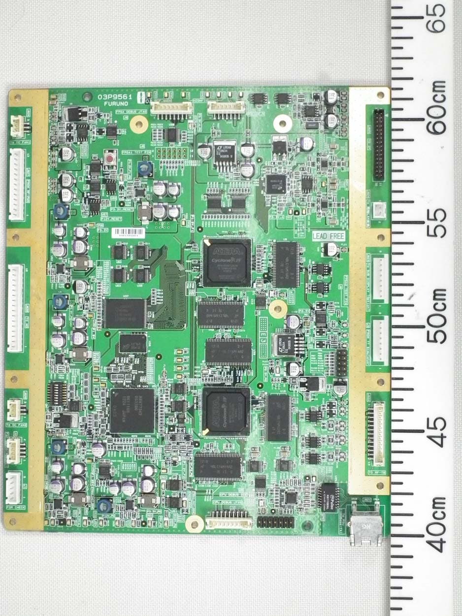
Click to zoom
Application Details
- Equipment Class
- MRD - Marine Radar
- Date of Grant
- Jan 09, 2015
- Application Purpose
- Original Equipment
- Date of Application
- Jan 09, 2015
- Equipment Note
- Transceiver for Radar model FAR-3330SW
- Frequency Range
- 3050.00000000 - 3050.00000000
- Company
- Furuno USA Inc
- Country
- United States
Documents & Files
Document Text
Text extracted from the exhibit documents filed with the FCC. Open a document above to read the original.
Users Manual
OPERATOR'S MANUAL www.furuno.com CHART RADAR FAR-3210 FAR-3220 FAR-3230S FAR-3230S-SSD FAR-3310 FAR-3320 FAR-3330S FAR-3330S-SSD FAR-3320W FAR-3330SW FAR-3210-BB FAR-3220-BB FAR-3230S-BB FAR-3230S-SSD-BB FAR-3220W-BB FAR-3230SW-BB Model (Product Name: MARINE RADAR) The paper used in this manual is elemental chlorine free. ・FURUNO Authorized Distributor/Dealer 9-52 Ashihara-cho, Nishinomiya, 662-8580, JAPAN A:APR2014 . Printed in Japan All rights reserved. B2:DEC.15, 2014 Pub. No. OME-36160-B2 ( YOTA ) FAR-3000SERIES 0 0 0 1 7 8 0 2 7 1 1 i IMPORTANT NOTICES General How to discard this product Discard this product according to local regulations for the disposal of industrial waste. For disposal in the USA, see the homepage of the Electronics Industries Alliance (http://www.eiae.org/) for the correct method of disposal. How to discard a used battery Some FURUNO products have a battery(ies). To see if your product has a battery, see the chapter on Maintenance. Follow the instructions below if a battery is used. Tape the + and - terminals of battery before disposal to prevent fire, heat generation caused by short circuit. In the European Union The crossed-out trash can symbol indicates that all types of batteries must not be discarded in standard trash, or at a trash site. Take the used batteries to a battery collection site according to your national legislation and the Batteries Directive 2006/66/EU. In the USA The Mobius loop symbol (three chasing arrows) indicates that Ni-Cd and lead-acid rechargeable batteries must be recycled. Take the used batteries to a battery collection site according to local laws. In the other countries There are no international standards for the battery recycle symbol. The number of symbols can increase when the other countries make their own recycle symbols in the future. • This manual has been authored with simplified grammar, to meet the needs of international users. • The operator of this equipment must read and follow the descriptions in this manual. Wrong oper- ation or maintenance can cancel the warranty or cause injury. • Do not copy any part of this manual without written permission from FURUNO. • If this manual is lost or worn, contact your dealer about replacement. • The contents of this manual and equipment specifications can change without notice. • The example screens (or illustrations) shown in this manual can be different from the screens you see on your display. The screens you see depend on your system configuration and equipment settings. • Save this manual for future reference. • Any modification of the equipment (including software) by persons not authorized by FURUNO will cancel the warranty. • All brand and product names are trademarks, registered trademarks or service marks of their re- spective holders. • “C-MAP” means “C-MAP by Jeppesen” in this manual. • Windows is a registered trademark of the Microsoft Corporation of the USA and other countries. Cd Ni-CdPb ii SAFETY INSTRUCTIONS The operator must read the safety instructions before attempting to operate the equipment. The radar antenna emits electromagnetic radio frequency (RF) energy that can be harmful, particularly to your eyes. Never look directly into the antenna aperture from a close distance while the radar is in operation or expose yourself to the transmitting antenna at a close distance. Distances at which RF radiation level of 100, 50 and 10 W/m 2 are given in the table below. Indicates a potentially hazardous situation which, if not avoided, could result in death or serious injury. Indicates a potentially hazardous situation which, if not avoided, could result in minor or moderate injury. 100W/m 2 Radar model FAR-3220/ FAR-3320/ FAR-3220-BB FAR-3210/ FAR-3310/ FAR-3210-BB FAR-3230S/ FAR-3330S/ FAR-3230S-BB FAR-3330SW/ FAR-3230SW-BB FAR-3320W/ FAR-3220W-BB TransceiverMagnetronAntenna 10W/m 2 50W/m 2 Warning, CautionProhibitive Action Mandatory Action Radio Frequency Radiation Hazard WARNING CAUTION WARNING RTR-105 FNE1201 XN12CF XN20CF XN24CF RTR-106 MG5436 XN12CF XN20CF XN24CF RTR-108 MG5436 XN20CF XN24CF RTR-107 MG5223F SN36CF RTR-109 MG5223F SN36CF Magnetron radar 100W/m 2 Radar model FAR-3230S-SSD/ FAR-3330S-SSD/ FAR-3230S-SSD-BB TransceiverAntenna 10W/m 2 50W/m 2 RTR-111 SN36CF Solid state radar N/A N/A N/A 1.0 m 0.5 m4.6 m 0.6 m 1.4 m4.4 m 0.4 m 0.9 m3.0 m 0.3 m 0.6 m2.5 m 1.3 m 2.7 m9.5 m 1.0 m 1.7 m6.8 m 0.7 m 1.3 m5.5 m N/A 0.26 m2.3 m 0.5 m 1.2 m5.5 m 0.3 m 0.9 m4.0 m SAFETY INSTRUCTIONS iii WARNING Do not open the equipment. The equipment uses high voltage that can cause electrical shock. Refer any repair work to a qualified technician. Before turning on the radar, be sure no one is near the antenna. Prevent the potential risk of being struck by the rotating antenna, which can result in serious injury or death. If water leaks into the equipment or something is dropped into the equipment, immediately turn off the power at the switchboard. Fire or electrical shock can result. If the equipment is giving off smoke or fire, immediately turn off the power at the switchboard. Fire or electrical shock can result. If you feel the equipment is acting abnormally or giving off strange noises, immediately turn off the power at the switchboard and contact a FURUNO service techni- cian. Do not disassemble or modify the equipment. Fire, electrical shock or serious injury can result. Make sure no rain or water splash leaks into the equipment. Fire or electrical shock can result if water leaks into the equipment. Do not place liquid-filled containers on or near the equipment. Fire or electrical shock can result if a liquid spills into the equipment. Do not operate the equipment with wet hands. Electrical shock can result. Keep objects away from the open- type antenna unit, so as not to impede rotation of the antenna. Fire, electrical shock or serious injury can result. Use the proper fuse. Use of the wrong fuse can cause fire or damage the equipment. The TT function is a valuable…
Text truncated - open the document above for the full version.
Users Manual
OPERATOR'S MANUAL www.furuno.com CHART RADAR FAR-3210 FAR-3220 FAR-3230S FAR-3230S-SSD FAR-3310 FAR-3320 FAR-3330S FAR-3330S-SSD FAR-3320W FAR-3330SW FAR-3210-BB FAR-3220-BB FAR-3230S-BB FAR-3230S-SSD-BB FAR-3220W-BB FAR-3230SW-BB Model (Product Name: MARINE RADAR) The paper used in this manual is elemental chlorine free. ・FURUNO Authorized Distributor/Dealer 9-52 Ashihara-cho, Nishinomiya, 662-8580, JAPAN A:APR2014 . Printed in Japan All rights reserved. B2:DEC.15, 2014 Pub. No. OME-36160-B2 ( YOTA ) FAR-3000SERIES 0 0 0 1 7 8 0 2 7 1 1 i IMPORTANT NOTICES General How to discard this product Discard this product according to local regulations for the disposal of industrial waste. For disposal in the USA, see the homepage of the Electronics Industries Alliance (http://www.eiae.org/) for the correct method of disposal. How to discard a used battery Some FURUNO products have a battery(ies). To see if your product has a battery, see the chapter on Maintenance. Follow the instructions below if a battery is used. Tape the + and - terminals of battery before disposal to prevent fire, heat generation caused by short circuit. In the European Union The crossed-out trash can symbol indicates that all types of batteries must not be discarded in standard trash, or at a trash site. Take the used batteries to a battery collection site according to your national legislation and the Batteries Directive 2006/66/EU. In the USA The Mobius loop symbol (three chasing arrows) indicates that Ni-Cd and lead-acid rechargeable batteries must be recycled. Take the used batteries to a battery collection site according to local laws. In the other countries There are no international standards for the battery recycle symbol. The number of symbols can increase when the other countries make their own recycle symbols in the future. • This manual has been authored with simplified grammar, to meet the needs of international users. • The operator of this equipment must read and follow the descriptions in this manual. Wrong oper- ation or maintenance can cancel the warranty or cause injury. • Do not copy any part of this manual without written permission from FURUNO. • If this manual is lost or worn, contact your dealer about replacement. • The contents of this manual and equipment specifications can change without notice. • The example screens (or illustrations) shown in this manual can be different from the screens you see on your display. The screens you see depend on your system configuration and equipment settings. • Save this manual for future reference. • Any modification of the equipment (including software) by persons not authorized by FURUNO will cancel the warranty. • All brand and product names are trademarks, registered trademarks or service marks of their re- spective holders. • “C-MAP” means “C-MAP by Jeppesen” in this manual. • Windows is a registered trademark of the Microsoft Corporation of the USA and other countries. Cd Ni-CdPb ii SAFETY INSTRUCTIONS The operator must read the safety instructions before attempting to operate the equipment. The radar antenna emits electromagnetic radio frequency (RF) energy that can be harmful, particularly to your eyes. Never look directly into the antenna aperture from a close distance while the radar is in operation or expose yourself to the transmitting antenna at a close distance. Distances at which RF radiation level of 100, 50 and 10 W/m 2 are given in the table below. Indicates a potentially hazardous situation which, if not avoided, could result in death or serious injury. Indicates a potentially hazardous situation which, if not avoided, could result in minor or moderate injury. 100W/m 2 Radar model FAR-3220/ FAR-3320/ FAR-3220-BB FAR-3210/ FAR-3310/ FAR-3210-BB FAR-3230S/ FAR-3330S/ FAR-3230S-BB FAR-3330SW/ FAR-3230SW-BB FAR-3320W/ FAR-3220W-BB TransceiverMagnetronAntenna 10W/m 2 50W/m 2 Warning, CautionProhibitive Action Mandatory Action Radio Frequency Radiation Hazard WARNING CAUTION WARNING RTR-105 FNE1201 XN12CF XN20CF XN24CF RTR-106 MG5436 XN12CF XN20CF XN24CF RTR-108 MG5436 XN20CF XN24CF RTR-107 MG5223F SN36CF RTR-109 MG5223F SN36CF Magnetron radar 100W/m 2 Radar model FAR-3230S-SSD/ FAR-3330S-SSD/ FAR-3230S-SSD-BB TransceiverAntenna 10W/m 2 50W/m 2 RTR-111 SN36CF Solid state radar N/A N/A N/A 1.0 m 0.5 m4.6 m 0.6 m 1.4 m4.4 m 0.4 m 0.9 m3.0 m 0.3 m 0.6 m2.5 m 1.3 m 2.7 m9.5 m 1.0 m 1.7 m6.8 m 0.7 m 1.3 m5.5 m N/A 0.26 m2.3 m 0.5 m 1.2 m5.5 m 0.3 m 0.9 m4.0 m SAFETY INSTRUCTIONS iii WARNING Do not open the equipment. The equipment uses high voltage that can cause electrical shock. Refer any repair work to a qualified technician. Before turning on the radar, be sure no one is near the antenna. Prevent the potential risk of being struck by the rotating antenna, which can result in serious injury or death. If water leaks into the equipment or something is dropped into the equipment, immediately turn off the power at the switchboard. Fire or electrical shock can result. If the equipment is giving off smoke or fire, immediately turn off the power at the switchboard. Fire or electrical shock can result. If you feel the equipment is acting abnormally or giving off strange noises, immediately turn off the power at the switchboard and contact a FURUNO service techni- cian. Do not disassemble or modify the equipment. Fire, electrical shock or serious injury can result. Make sure no rain or water splash leaks into the equipment. Fire or electrical shock can result if water leaks into the equipment. Do not place liquid-filled containers on or near the equipment. Fire or electrical shock can result if a liquid spills into the equipment. Do not operate the equipment with wet hands. Electrical shock can result. Keep objects away from the open- type antenna unit, so as not to impede rotation of the antenna. Fire, electrical shock or serious injury can result. Use the proper fuse. Use of the wrong fuse can cause fire or damage the equipment. The TT function is a valuable…
Text truncated - open the document above for the full version.
Users Manual
1. OPERATIONAL OVERVIEW 1-31 1.20The Settings Menu The [Settings] button gives you access to the user profiles and the [Settings] menu. The [Settings] menu has facilities for screenshot management, file management, di- agnostic tests and customizing. See chapter 22. 1.21User Profiles for Radar, Chart Radar The [Settings] button lets you store ten sets of custom settings and color settings (ech- oes, TT and AIS symbols and echo trails). This allows individual users to quickly set the system according to their preferences. 1.21.1How to create a profile 1. Set the settings (echoes, TT and AIS symbols, echo trail, etc.) as desired. 2. Click [] on the Status bar then click [Manage Profile]. 3. Select a profile number from the “Profile” drop- down list. Note: Profiles 06-10 are disabled in the default set- ting. To enable a disabled profile, select the profile to enable from the “Profile” drop-down list then un- check [Disable this profile]. 4. Click [Save Current Settings]. 1.21.2How to disable a profile Select the profile to disable from the “Profile” drop-down list then check [Disable this profile]. Profile 01 cannot be disabled. 1.21.3How to activate a profile 1. Click [] on the Status bar. 2. Click the profile number to activate. The confir- mation message "Attention: Settings will be changed to Profile XX. Do you wish to contin- ue?" appears. 3. Click [Yes]. [Settings] button Profiles (enabled) 1. OPERATIONAL OVERVIEW 1-32 1.21.4How to restore a profile to the default settings 1. Click [] on the Status bar then click [Manage Profile]. 2. Select a profile number from the “Profile” drop-down list. 3. Click [Restore Default Settings]. The confirmation message "Attention: This profile will be restored to the default. Do you wish to continue?" appears. 4. Click [Yes]. Note: This setting for the default is available when selecting a profile to activate next time (see paragraph 1.21.3). 1.21.5How to change the settings on the current display to the rec- ommended settings 1. Click [] on the Status bar. 2. Click [Default Settings]. The confirmation message "Attention: Settings will be changed to the default. Do you wish to continue?" appears. 3. Click [Yes]. The settings on the following table are changed to the recommended settings. Note: This function is not available when using the interswitch function (see section 2.29). ItemsSettings RAIN, SEAAUTO GAIN, EAVNo change Automatic Clutter Elimina- tion (ACE) OFF TUNE (other than solid state radar) TUNE AUTO TX CH (for solid state ra- dar) No change RANGE6 NM, 6 SM, 6 km, 6 kyd VRM10.25 NM, 0.25 SM, 0.25 km, 0.25 kyd VRM2OFF (No change) EBL1ON (No change) EBL2OFF (No change) Presentation modeNorth-up TM Note: Head-up RM with no heading or position data. Off CenterThe ship’s position is put beyond 75% of the range scale. TrailTrail time: 6 min, Trail mode: True-G Past POSNOFF Lost TGTOFF TT ACQNo change Note: TT OFF with no heading data. VectorVector time: 6 min, Vector reference: REL AZ1, AZ2 (acquisition zone) OFF AISDISP ALL Note: FUNC OFF with no heading or position data. AssociationTT (>) CPA/TCPACPA: 2 NM, TCPA: 12 min 1. OPERATIONAL OVERVIEW 1-33 1.22How to View Chart Software Version No., Chart System Information, and Operator's Manual You can show chart program no., chart system information, and the operator's manual as follows: 1. Click the [Operating Mode] button at the left end of the Status bar to select [Chart for Radar]. 2. Click the [?] button on the Status bar. 3. Select [Manual] to show the operator's manual, or [About] to show chart and sys- tem information. On the [About] screen, click the [Version] tab to show the chart software version no., conning software version no., S52 presentation library version, ENC user permit no., and C-MAP SDK software version no. Click the [System 1] tab to show system infor- mation: CPU type, RAM capacity, SSD free/SSD capacity, Equipment ID and dongle information. [Function] shows the system’s capabilities. Click the [System 2] tab to show the startup time for this equipment. AIS CPAAUTO ACT ALL Operating modeRADAR MAP (Radar map)No change RouteNo change AlertAZ1/AZ2: OFF, Lost TGT: OFF Antenna connection statusNo change RANGE RINGOFF PI LINEPI1 to PI6: OFF Number of PI line, mode, bearing range truncate: No change SPD (Own Ship Sensor Setting) Stabilization Mode: Bottom* Sensor Type: GPS* Sensor Setting: No change (System or Local) *: These settings can not be applied, the settings are changed according to the priority order of SPD. ItemsSettings [?] button 1. OPERATIONAL OVERVIEW 1-34 The information shown in the following illustration may be different from those on your system. 1.23Tips (operational guidance) This chart radar provides operational tips for the display area, InstantAccess bar and Mark box. To get a tip, simply put the cursor on the object. For example, put the cursor on the [BRILL] button on the InstantAccess bar. The tip "Adjust brilliance" appears. If you do not need the tips, you can turn them off with [TIPS GUIDANCE] in the [INI- TIAL SETTING] menu. XXXXXXXXXXXXXXXXXXXXXXXXXXXX [Version] tab [System 1] tab [System 2] tab Startup Time :06 Jan 2014 09:23:20 Equipment ID : Function : ecdis,radar Tip 2-1 2.RADAR, CHART RADAR OPERATION 2.1How to Transmit After the power is turned on and the magnetron has warmed*, "ST-BY" appears at the screen center, meaning the radar is ready to transmit radar pulses. You can transmit by pushing the STBY/TX key on the Control Unit, or clicking the [STBY TX] button on the Status bar. *: The solid state radar does not have a magnetron, therefore it has no warming peri- od. The radar is initially set to previously used range and pulse length. Other settings such as brilliance levels, VRMs, EBLs and menu option selections are also set to previous settings. The STBY/TX key (or [STBY TX] button) toggles the radar between STBY and TRANSMIT state. The antenna is stopped in stand-by and rotates in transmit. Set the radar in standby when its use is not re…
Text truncated - open the document above for the full version.
Users Manual
2. RADAR, CHART RADAR OPERATION 2-59 2.40Icing Prevention You can rotate the antenna (24 rpm) without transmission to keep the antenna from freezing. 1. Open the menu then select the [8 INITIAL SETTING] menu. Select [9 ICING PRE- VENTION] (IMO type) or [0 ICING PREVENTION] (A and B types). 2. Select [ON]. The following message appears at the bottom of the screen. 3. Click [Start Antenna Rotation] to rotate the antenna without transmission. The message changes as follow. To stop the antenna rotation, click [Stop Antenna Rotation]. With this feature active and the antenna stopped, pushing the STBY/TX key on the Control Unit or click the [STBY TX] button on the Status bar rotates the antenna and transmits pulses. Operating one of the above-mentioned controls again stops trans- mission but the antenna rotates. When the antenna stops When the antenna rotates [STBY TX] is grayed out. ICING PREVENTION Rotate Antenna to Prevent Icing. Start Antenna Rotation ICING PREVENTION Antenna Rotating, No TX. Stop Antenna Rotation ACE ACE 2. RADAR, CHART RADAR OPERATION 2-60 2.41Chart Radar Functions 2.41.1How to switch between radar and chart radar modes Click the [CHART ON/OFF] button on the InstantAccess bar to show or hide the chart. Indication on button and corresponding mode [Chart ON]: Chart radar mode active. (Chart and radar picture are displayed.) [Chart OFF]: Radar mode active. (Only the radar picture is displayed.) When the GPS position is lost, the chart radar mode cannot be used. When this oc- curs, the label on the button shows [Chart OFF] and the button is grayed out. 2.41.2How to show or hide chart objects The [Chart Disp] button on the InstantAccess bar has several buttons which control chart object visibility. No.ItemFunction 1[Coast Line Only]Hold down the left button to temporarily display only the coastline. Chart symbols (depth contours, navigation buoys, etc.) are temporarily erased from the screen. 2[Chart Top Layer]Hold down the left button to temporarily put the chart objects (buoy, lighthouse, etc.) on the top layer. 3[Chart DISP Menu] Show the [CHART DISPLAY] menu, where you set safety contours, safety depth, etc. See the figure on the next page for the content of this menu and see section 8.2 "How to Control Visibility of Chart Objects" for details. Note: This menu can also be shown by right-clicking the [CHART ON/OFF] button and selecting [Chart Display Menu]. 4[Sel DISP Object]Show the [SEL DISPLAY OBJECT] menu, where you can select the chart objects and text to show or hide. See the next page for the menus and see section 8.3 "How to Con- trol Visibility of Symbols, Features" (symbol display) for de- tails. [Chart ON/OFF] button 12345 2. RADAR, CHART RADAR OPERATION 2-61 [CHART DISPLAY] menu 5[Chart Legend]Show the chart legend for the current chart. See chapters 9 and 10 for a description of the chart legends. No.ItemFunction 2. RADAR, CHART RADAR OPERATION 2-62 [SEL DISPLAY OBJECT] menu 2.41.3How to create and recall custom sets of chart display objects You can create one custom set of chart display objects and recall them when required. For example, you can create a custom set of chart display objects to display when you navigate a certain coastline. How to create a custom set of chart display objects 1. Open the menu then select the [6 CHART DISPLAY] and [2 SEL DISPLAY OB- JECT] menus. 2. Open the [2 STANDARD ITEMS], [3 OTHER ITEMS], [4 IMPORTANT TEXT] and [5 OTHER TEXT] menus and turn objects and text on or off as appropriate. 3. Click [SEL DISPLAY OBJECT] on the menu. 4. Select [1 SAVE TO PERSONAL] to save the settings. The confirmation message "Attention: Do you wish to overwrite current settings to PERSONAL?" appears. 5. Click the [OK] button to save the settings. How to activate the custom set of chart display objects Click the [Chart database] button (see paragraph 2.41.4) on the Status bar then select [PERSONAL]. [STANDARD ITEMS] [OTHER ITEMS] [OTHER TEXT] [IMPORTANT TEXT] 2. RADAR, CHART RADAR OPERATION 2-63 2.41.4Chart database information You can select the quantity of objects and text to display on the chart radar screen, with the [Chart database] button on the Status bar. There are four different pre-defined settings available and one user-definable ([PERSONAL]). Indication of selected set- ting appears on the label of the [Chart database] button. The [Chart ON/OFF] button (on the InstantAccess bar) must be ON to show the [Chart database] button. The [Chart database] button is grayed out if the [Chart ON/OFF] button is OFF. 2.41.5Chart scale indications The system alerts you to the availability of larger scale ENC and overscale, at the top-left posi- tion. When the radar display range is higher than the chart scale of the ENC chart, the indication, "Larger scale ENC" is displayed. For example, the radar range is 24 NM and the range avail- able with the ENC chart is less than 12 NM. When the radar display range is lower than the chart scale of the ENC chart, the indication "Overscale x.xx" (x.xx=overscale factor). For ex- ample, the radar range is 0.25 NM and the chart scale is 0.5 NM. If both conditions exist, both indications are displayed. 2.41.6Chart status The indication "Chart Status" appears at the top-right position on the screen when the display date for the currently displayed chart has passed. [Chart database] buttonSelectionSetting in [SEL DISP OBJECT] menu [IMO Base]Nothing checked in [STANDARD ITEMS], [OTHER ITEMS] or [IMPORTANT TEXT]. [IMO Primary]Nothing else checked but [BUOYS AND BEACONS] in [STANDARD ITEMS]. This is the "Primary Chart Infor- mation Set (PCIS)", based on IEC 62388 Ed.2 section12.1.5.1, IEC61174 and IMO Resolution MSC.232(82). [IMO Standard] All objects checked in [STANDARD ITEMS]; nothing checked in [OTHER ITEMS] or [IMPORTANT TEXT]. [IMO All]Everything checked in [STANDARD ITEMS], [OTHER ITEMS] and [IMPORTANT TEXT]. [PERSONAL]Use the settings recorded for [STANDARD ITEMS], [OTHER ITEMS], [IMPORTANT TEXT] and [OTHER TEXT]. L…
Text truncated - open the document above for the full version.
Users Manual
4. AIS OPERATION 4-13 4.12.2Past position points You can show 5 or 10 past position points per AIS target. Right-click the past position indication then click [Past POSN Menu] to show that menu. Set [6 AIS PAST POSN POINTS] to [5] or [10]. 4.13How to Display True or Relative Speed Vectors AIS targets vector can be displayed relative to your ship's heading (relative) or with reference to the North (True). Vector time (or the length of vectors) and presentation mode can be set at the bottom- right position on the screen. For further information, see section 3.9. 4.14Association of TT and AIS Targets An AIS-equipped ship is usually displayed by two symbols on the radar display. This is because the AIS ship position is measured by a GPS navigator (L/L) whereas the radar detects the same ship by PPI principle (range and bearing relative to own ship radar antenna). To avoid the presentation of two target symbols for the same physical target, use the "association" function. If target data from both AIS and TT are available and if the as- sociation criteria are fulfilled, either the AIS or TT symbol is presented according to the association method selected. Association will not happen between AIS and TT if the AIS target is sleeping or the AIS target is lost. All association settings, including ON/OFF, can also be controlled from the chart for radar mode, with the [TT/AIS] page in the [Overlay/NAV Tools] box. All settings are mutually shared. 4.14.1How to select association method Click the location circled below to show "<" to select AIS symbol for associated target, or ">" to select TT symbol for associated target. This setting overrides the correspond- ing item on the [TT•AIS] menu. To turn off association, click the location to remove the arrow. Note: You can also select the method by right-cllcking the loca- tion. Click desired association method. <<> Association: OFF Association: TT Association: AIS [Association Menu] 4. AIS OPERATION 4-14 4.14.2How to set the conditions for association 1. Open the menu then select [TT•AIS] and [6 ASSOCIA- TION]. 2. Enter the association conditions, referring to the follow- ing: [ASSOCIATION TGT]: Disable Association with [OFF], or select [AIS] or [TT]. [AIS] selects the AIS symbol for asso- ciation target; [TT] selects the TT symbol for the associa- tion target. [GAP]: Range between AIS target and TT. Setting range: 0.000-0.999(NM) [RANGE]: Enter the range difference from own ship to AIS target and TT. setting range: 0.000-0.999(NM) [BEARING]: Enter the bearing difference from own ship to AIS target and TT. Setting range: 0.0-99.9(°) [SPEED]: Enter the speed difference between AIS target and TT. Setting range: 0.0-9.9(kn) [COURSE]: Enter the course difference between AIS target and TT. Setting range: 0.0-99.9(°) When the association criteria are met • either the AIS or TT symbol is erased according to association made in section 4.14.1. • the Alert 560 "Association" appears in the [Alert] box. 4.15Voyage Data Before you embark on a voyage, set your navigation status, ETA, destination, draught and crew, on the [VOYAGE DATA] menu. 1. Click the [OWN AIS] button on the InstantAccess bar to show the [VOYAGE DA- TA] menu. 4. AIS OPERATION 4-15 2. Select [1 NAV STATUS] then use the scrollwheel to set the applicable two-digit nav status code, referring to the table below. 3. Select [2 ETA] then use the scrollwheel to enter ETA: day (two digits), month (two digits), year (four digits) and time (four digits). 4. Select [3 DESTINATION] then use the software keyboard to enter the name of your destination, using a maximum of 20 characters. 5. Select [4 DRAUGHT] then use the scrollwheel to enter ship's draft (0.0 - 25.5 (m)). 6. Select [5 CREW] then use the scrollwheel to enter the number of crew (0000- 8191). 7. Close the menu. 4.16AIS Messages You can send and receive messages via the VHF link, to a specified destination (MM- SI) or all AIS-equipped ships within communication range of your ship. Messages can be sent to warn of safety of navigation, for example, an iceberg sighted. Routine mes- sages are also permitted. Short safety-related messages are only an additional means to broadcast safety information. They do not remove the requirements of the GMDSS. 4.16.1How to create and transmit a new AIS message You can create and send an AIS message as follows: 1. Right-click the AIS mode indication then click [AIS Menu] to show that menu. 2. Open the [8 TRANSMIT MESSAGE] menu. 3. At [1 ADDRESS TYPE], select [ADDRESSED] to send the message to a specific AIS-equipped ship, or [BROAD- CAST] to send the message to all AIS-equipped ships within VHF communication range. For [ADDRESSED], enter MMSI of ship at [3 MMSI No.]. 4. At [2 MESSAGE TYPE], select [SAFETY] for safety mes- sage, or [BINARY] for routine message. No.Nav statusNo.Status 00Underway using engine08Under way Sailing 01At anchor09Reserved for high speed craft 02Not under command10Reserved for wing in ground 03Restricted Maneuverability11Reserved for future use 04Constrained by her draft12Reserved for future use 05Moored13Reserved for future use 06Aground14AIS SART 07Engaged in fishing15Not Defined 4. AIS OPERATION 4-16 5. At [4 CHANNEL], select the channel over which to broad- cast your message. The choices are [A], [B], [A or B] or [A and B]. 6. Click [NEXT] to go to the next page. 7. Select [3 EDIT]. A text input box appears together with the software keyboard. Use the software keyboard to enter your message. The number of characters that may be en- tered depends on message type, and the number of char- acters available appears below the text box. Safety message broadcast: 161 characters Binary message broadcast: 156 characters Safety message addressed to MMSI: 156 characters Binary message addressed to MMSI: 151 characters 8. To save the file, select [2 SAVE FILE]. 9. To transmit the message, click [4 TRANSMIT MESSAGE]. The confirmation mes- sage "Attention: Do you wish to transmit AIS message?" appears. Clic…
Text truncated - open the document above for the full version.
Contact Information
Applicant
Bill Haynes(Deep Sea Product Manager)
Test Firm
Labotech International Co., Ltd.Yoshihiro Ishii
Technical Specifications
| # | Rule Parts | Frequency Range | Power Output | Emission | Tolerance |
|---|---|---|---|---|---|
| 1 | 80 | 3.05 GHz - 3.05 GHz | 30000 W | 51M7P0N | 30000.0000000000 Hz |
Other Applications from Furuno USA Inc
ADB-9ZWRTR137
Feb 18, 2026Transceiver unit for the radar sensor
Equipment Class
MRD - Marine RadarADB9ZWRTR136
Jul 01, 2024Transceiver unit for the radar sensor
Equipment Class
MRD - Marine Radar
ADB9ZWRTR128
Apr 06, 2022Transceiver unit for the radar sensor
Equipment Class
MRD - Marine Radar
ADB9ZWRTR133
Sep 26, 2021Transceiver unit for the radar sensor
Equipment Class
MRD - Marine Radar
ADB9ZWRTR129
May 23, 2021Transceiver unit for the radar sensor
Equipment Class
MRD - Marine Radar