ADB9ZWRTR112Transceiver for Radar Sensor
Furuno USA Inc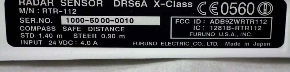
Click to zoom
Application Details
- Equipment Class
- MRD - Marine Radar
- Date of Grant
- Nov 23, 2015
- Application Purpose
- Original Equipment
- Date of Application
- Nov 23, 2015
- Equipment Note
- Transceiver for Radar Sensor
- Frequency Range
- 9410.00000000 - 9410.00000000
- Company
- Furuno USA Inc
- Country
- United States
Documents & Files
Document Text
Text extracted from the exhibit documents filed with the FCC. Open a document above to read the original.
Users Manual
www.furuno.com All brand and product names are trademarks, registered trademarks or service marks of their respective holders. Installation Manual RADAR SENSOR Model DRS6A X-Class SAFETY INSTRUCTIONS ................................................................................................ i SYSTEM CONFIGURATION .......................................................................................... iii EQUIPMENT LISTS........................................................................................................ iv 1. INSTALLATION AND WIRING................................................................................... 1 1.1 Mounting Considerations ......................................................................................................1 1.2 Included Items....................................................................................................................... 3 1.3 Required Tools and Materials ............................................................................................... 4 1.4 Fastening the Radiator to the Radiator Bracket.................................................................... 5 1.5 Mounting the Antenna Unit ...................................................................................................7 1.6 Wiring.................................................................................................................................. 10 2. INITIAL SETUP......................................................................................................... 13 2.1 Initial Setup for TZT9/TZT14/TZTBB .................................................................................. 13 2.2 Initial Setup for TZTL12F/TZTL15F .................................................................................... 16 3. MAINTENANCE, TROUBLE SHOOTING................................................................ 18 3.1 Maintenance ....................................................................................................................... 19 3.2 Troubleshooting .................................................................................................................. 19 3.3 Replacement of Fuse..........................................................................................................20 3.4 Life of Parts......................................................................................................................... 20 SPECIFICATIONS ..................................................................................................... SP-1 OUTLINE DRAWING ................................................................................................... D-1 INTERCONNECTION DIAGRAM ................................................................................ S-1 i SAFETY INSTRUCTIONS Mandatory Action Prohibitive Action WARNING CAUTION Warning, Caution WARNING The installer of the equipment must read the safety instructions before attempting to install the equipment. Indicates a potentially hazardous situation which, if not avoided, could result in death or serious injury. Indicates a potentially hazardous situation which, if not avoided, can result in minor or moderate injury. WARNING Turn off the power at the switchboard before beginning the installation. Fire or electrical shock can result if the power is left on. Do not open the equipment unless you are well familiar with electrical circuits. Only qualified personnel should work inside the equipment. Be sure that the power supply is compatible with the voltage rating of the equipment. Connection of an incorrect power supply can cause fire or damage the equipment. Use only the specified power and signal cable. Fire or damage to the equipment can result if a different cable is used. Wear a safety belt and hard hat when working on the antenna unit. Serious injury or death can result if someone falls from the radar mast. Do not disassemble or modify the equipment. Fire, electrical shock or serious injury can result. Construct a suitable service platform from which to install the antenna unit. Serious injury or death can result if someone falls from the radar mast. Keep the objects away from the antenna unit, so as not to impede rotation of the antenna. Fire, electrical shock or serious injury can result. Use the proper fuse. Use of a wrong fuse can damage the equipment or cause fire. Do not depend one navigation device for the navigation of the vessel. For the safety of vessel and crew, the navigator must check all aids available to confirm position. SAFETY INSTRUCTIONS ii Ground the equipment to prevent mutual interference. The radar antenna emits electromagnetic radio frequency (RF) energy which can be harmful, particularly to your eyes. Never look directly into the antenna aperture from a close distance while the radar is in operation or expose yourself to the transmitting antenna at a close distance. Distances at which RF radiation levels of 100, 50 and 10 W/m 2 exist are given in the table below. WARNING LABEL A warning label is attached to the antenna unit. Do not remove the label. If the label is missing or damaged, contact your dealer about replacement. Name: Warning Label (2) Type: 03-129-1001-3 Code No: 100-236-743 It is recommended that you connect the antenna unit to a disconnecting device (circuit breaker, etc.) to control the power. CAUTION Observe the following compass safe distances to prevent deviation of a magnetic compass: WARNING 0.1mXN10A3m0.5m 100 W/m 2 50 W/m 2 10 W/m 2 Radiator 1.40 m DRS6A X-Class 0.90 m Model Standard compass Steering compass XN12A XN13A N/A2.2m0.4m N/A1.9m0.2m iii SYSTEM CONFIGURATION The DRS6A X-Class is compatible with the FURUNO Multi Function Displays shown below. The combination with other models may not operate properly. • NavNet TZtouch: TZT9, TZT14, TZTBB • NavNet TZtouch2: TZTL12F, TZTL15F : Standard supply : Optional or local supply Antenna Unit RSB-134 Multi Function Dis…
Text truncated - open the document above for the full version.
Users Manual
1. INSTALLATION AND WIRING 11 3. Wrap the junction of the connectors with self-vulcanizing tape and vinyl tape (lo- cally supply) for waterproofing as follows: 4. As shown in the figure below, attach a ground wire (IV-2sq, local supply) between the ship’s ground and the screw on the cable cover of the antenna unit. 5. Apply the silicone rubber about ground point of the ship’s ground. Self-vulcanizing tape 1) Wrap the junction of the connectors with one layer of self-vulcanizing tape. 2) Change wrap direction and wrap one layer of the self-vulcanizing tape again. Self-vulcanizing tape 3) Wrap one layer of the vinyl tape over the self-vulcanizing tape. Vinyl tape 4) Change wrap direction and wrap one layer of the vinyl tape again. Vinyl tape Ship’s ground Terminal screw* Ground wire from the ship’s ground Ground wire* from the antenna unit *: Pre-attached to the cable cover. Cable cover Weld here. Hex. bolt Flat washer Flat washer Spring washer Hex. nut OR Hex. nut Hex. nut Spring washer Flat washer Ground wire Ground wire Silecone rubber Ground point Weld here. 1. INSTALLATION AND WIRING 12 6. Fix the power/LAN cable to the cable cover with the cable ties (locally supply) as shown in the figure below. 7. Reattach the cable cover. 8. Connect the LAN connector of the power/LAN cable to a LAN port on the FURU- NO Multi Function Display or Ethernet HUB. Note: Do not connect the LAN connector to on-board LAN. 9. Connect the power wires to the ship’s battery (24 VDC). • Red wire: Connect to the positive terminal. The red wire has the fuse holder. • Blue wire: Connect to the negative terminal. • Black wire: The black wire is a shielding wire for grounding. Note 1: The antenna unit has no power switch. Connect the antenna unit to a dis- tribution switchboard with a switch for power control. Note 2: If the voltage of the ship’s battery is 12 VDC, prepare a DC-to-DC con- verter whose output current is 10 A or more. Note 3: The antenna unit cannot accept the input voltage more than 24 VDC. Fix the cable with cable tie.Fix the cable with cable tie. Ground wire from the ship's ground Ground wire from the ship's ground Power/LAN cablePower/LAN cable Antenna cableAntenna cable Ground wire from the antenna unit Ground wire from the antenna unit If the power/LAN cable is run through a radar mast and the bottom of the uni, fix the cable to this cable clamp. If the power/LAN cable is run through a radar mast and the bottom of the uni, fix the cable to this cable clamp. Power/LAN cable LAN connector Ethernet HUB OR FURUNO Multi Function Display LAN cable To antenna unit Power/LAN cable Shield Distribution switchboard Ship's battery (24 VDC) Fuse holder 13 2.INITIAL SETUP The DRS6A X-Class is compatible with the FURUNO Multi Function Display shown below. The combination with other models may not operate properly. • NavNet TZtouch: TZT9, TZT14, TZTBB • NavNet TZtouch2: TZTL12F, TZTL15F Turn on the antenna unit and FURUNO Multi Function Display, and do the initial setup for the antenna unit on the FURUNO Multi Function Display. 2.1Initial Setup for TZT9/TZT14/TZTBB 1. Press the Home key (or tap the Home icon). 2. Select [Menu] on the menu icon bar to open the main menu. 3. Select [Radar]. 4. Select [Radar Source] on the [Menu Radar] sub menus, then select the radar type connected. Note: If the antenna unit is connected but does not appear in the [Radar Source] list, close the list and open it again. The name of the antenna unit should appear with a check mark, as in the example below. Before turning on the radar, be sure no one is near the antenna. Prevent the potential risk of being struck by the rotating antenna, which can result in serious injury or death. WARNING WARNING The radar antenna emits electromagnetic radio frequency (RF) energy which can be harmful, particularly to your eyes. Never look directly into the antenna aperture from a close distance while the radar is in operation. Distances at which RF radiation levels of 100, 50 and 10 W/m 2 exist are given in the table below. 0.1mXN10A3m0.5m 100 W/m 2 50 W/m 2 10 W/m 2 Radiator XN12A XN13A N/A2.2m0.4m N/A1.9m0.2m 2. INITIAL SETUP 14 5. Drag the [Menu Radar] sub menus to find the menu item [Radar Initial Setup]. 6. Set the items referring to the table shown below Menu Radar (Radar Initial Setup) Menu itemDescription [Antenna Rotation]Select the speed of antenna rotation. [Antenna Heading Align] See the topic of "How to align the antenna heading" on page 15. [Main Bang Suppres- sion] If main bang appears at the screen center, slide the circle icon so that the main bang disappears, while watching the radar echo at the left-hand side of the display. [Antenna Height]Select the height of the antenna above the waterline. [Antenna Longitudinal Position] Enter the antenna positioning bow-stern (Longitu- dinal) and port-starboard (lateral) position from the origin. [Antenna Lateral Posi- tion (-Port)] OthersSee Operator’ Manual for TZT9/14/BB. Title Origin 2. INITIAL SETUP 15 How to align the antenna heading You have mounted the antenna unit facing straight ahead in the direction of the bow. Therefore, a small but conspicuous target dead ahead visually should appear on the heading line (zero degrees). In practice, you will probably observe some small bearing error on the display because of the difficulty in achieving accurate initial positioning of the antenna unit. The follow- ing adjustment will compensate for the error. 1. Select a range between 0.125 and 0.25 NM and set the mode to “head up“. You can select a range by a pinch action. The range and range ring interval ap- pear at the bottom left of the screen. For TZTBB, you can also control the range in the operation as follows. Tap the radar scale box at the bottom left-hand corner of the screen to display the slider bar. Drag the circle icon to set the range scale. 2. Turn the vessel’s bow toward a target. 3. Press the Home key (or tap the Home icon), then select [Menu] icon, [Radar], and [Antenna Heading…
Text truncated - open the document above for the full version.
Cover Letter(s)
15 April 2014 TUV SUD BABT TCB/FCB Octagon House, Segensworth Road, Fareham, Hampshire, PO15 5RL Dear Sir or Madam, I, Shane Ryan of Furuno USA Inc , hereby authorize Akira Yamamoto and Ichiya Ogino of Furuno Electric Co., Ltd to act as our agent in all matters relating to applications for equipment authorization, including the signing of all documents relating to these matters. This authorization expires on 15 April 2016. Sincerely, Shane Ryan FURUNO USA Company Officer: Shane Ryan Telephone Number: (360) 834-9300 X-5060 Email: [email protected]
External Photos
Labotech International Report no.: LIC 01-15-048 Date of issue: 30 September 2015 - Page 1 of 3 - Photographs of Furuno Radar Sensor DRS6A X-Class 1 External View 1.1 Front View (without Antenna Radiator) Labotech International Report no.: LIC 01-15-048 Date of issue: 30 September 2015 - Page 2 of 3 - 1.2 Rear View Labotech International Report no.: LIC 01-15-048 Date of issue: 30 September 2015 - Page 3 of 3 - 1.3 Name Plate (ID Label)
ID Label/Location Info
Labotech International Document number: LIC 01-15-054 Date of issue: 30 September 2015 Form: Q053/01 - Page 1 of 2 - Identification of Equipment for the Furuno Radar Sensor DRS6A X-Class with Transceiver RTR-112 included (FCC Rule, 2.925) 1 ID Label The following nameplates are permanently fixed on the corresponding equipment units. FCC ID: ADB9ZWRTR112 Material of Nameplate: Polyester film, 0.1 mm thick Labotech International Document number: LIC 01-15-054 Date of issue: 30 September 2015 Form: Q053/01 - Page 2 of 2 - 2 ID Label Location ID Label is affixed on the Scanner case. ID Label
Internal Photos
Labotech International Report no.: LIC 01-15-049 Date of issue: 30 September 2015 - Page 1 of 21 - Photographs of Furuno Radar Sensor DRS6A X-Class 1 Internal View 1.1 Inside View (with front cover removed, showing Scanner Motor (upper) and Transceiver RTR-112 (middle)) Labotech International Report no.: LIC 01-15-049 Date of issue: 30 September 2015 - Page 2 of 21 - 1.2 Inside View (with Transceiver RTR-112 removed) Labotech International Report no.: LIC 01-15-049 Date of issue: 30 September 2015 - Page 3 of 21 - 1.3 Inside View (with Power module removed) Labotech International Report no.: LIC 01-15-049 Date of issue: 30 September 2015 - Page 4 of 21 - 1.4 Power module Top View Labotech International Report no.: LIC 01-15-049 Date of issue: 30 September 2015 - Page 5 of 21 - 1.5 Power module (with Shield-cover removed, showing PWR Board 03P9607) Labotech International Report no.: LIC 01-15-049 Date of issue: 30 September 2015 - Page 6 of 21 - 1.6 Power module (with PWR Board 03P9607 removed) Labotech International Report no.: LIC 01-15-049 Date of issue: 30 September 2015 - Page 7 of 21 - 1.7 Transceiver Front side View Isolator Limiter Filter Circulator Labotech International Report no.: LIC 01-15-049 Date of issue: 30 September 2015 - Page 8 of 21 - 1.8 Transceiver Left side View Labotech International Report no.: LIC 01-15-049 Date of issue: 30 September 2015 - Page 9 of 21 - 1.9 Transceiver Left side View (with Shield-cover removed, showing MD Board 03P9597 and Magnetron) Magnetron Labotech International Report no.: LIC 01-15-049 Date of issue: 30 September 2015 - Page 10 of 21 - 1.10 Transceiver Left side View (with MD Board 03P9597 removed) Labotech International Report no.: LIC 01-15-049 Date of issue: 30 September 2015 - Page 11 of 21 - 1.11 Transceiver Right side View Labotech International Report no.: LIC 01-15-049 Date of issue: 30 September 2015 - Page 12 of 21 - 1.12 Transceiver Right side View (with shield cover removed, showing SPU Board 03P9598) Labotech International Report no.: LIC 01-15-049 Date of issue: 30 September 2015 - Page 13 of 21 - 1.13 Transceiver Right side View (with SPU Board 03P9598 removed) Labotech International Report no.: LIC 01-15-049 Date of issue: 30 September 2015 - Page 14 of 21 - 1.14 Transceiver Right side View (with shield cover removed, showing MMIC Board 03P9604) Labotech International Report no.: LIC 01-15-049 Date of issue: 30 September 2015 - Page 15 of 21 - 1.15 Transceiver Right side View (with MMIC Board 03P9604 removed) Labotech International Report no.: LIC 01-15-049 Date of issue: 30 September 2015 - Page 16 of 21 - 1.16 Inside View Labotech International Report no.: LIC 01-15-049 Date of issue: 30 September 2015 - Page 17 of 21 - 1.17 Inside View (with motor module removed) Labotech International Report no.: LIC 01-15-049 Date of issue: 30 September 2015 - Page 18 of 21 - 1.18 Motor module Front side view Labotech International Report no.: LIC 01-15-049 Date of issue: 30 September 2015 - Page 19 of 21 - 1.19 Motor module Rear side view Labotech International Report no.: LIC 01-15-049 Date of issue: 30 September 2015 - Page 20 of 21 - 1.20 Motor module Rear side view (with shield cover removed, showing PCB 15DJ002) Labotech International Report no.: LIC 01-15-049 Date of issue: 30 September 2015 - Page 21 of 21 - 1.21 Motor module Rear side view (with PCB 15DJ002 removed)
Internal Photos
Labotech International Report no.: LIC 01-15-050 Date of issue: 30 September 2015 - Page 1 of 10 - Photographs of Furuno Radar Sensor DRS6A X-Class 1 PCBs 1.1 MD Board 03P9597 Front side Labotech International Report no.: LIC 01-15-050 Date of issue: 30 September 2015 - Page 2 of 10 - 1.2 MD Board 03P9597 Rear side Labotech International Report no.: LIC 01-15-050 Date of issue: 30 September 2015 - Page 3 of 10 - 1.3 SPU Board 03P9598 Front side Labotech International Report no.: LIC 01-15-050 Date of issue: 30 September 2015 - Page 4 of 10 - 1.4 SPU Board 03P9598 Rear side Labotech International Report no.: LIC 01-15-050 Date of issue: 30 September 2015 - Page 5 of 10 - 1.5 MMIC Board 03P9604 Front side Labotech International Report no.: LIC 01-15-050 Date of issue: 30 September 2015 - Page 6 of 10 - 1.6 MMIC Board 03P9604 Rear side Labotech International Report no.: LIC 01-15-050 Date of issue: 30 September 2015 - Page 7 of 10 - 1.7 PWR Board 03P9607 Front side Labotech International Report no.: LIC 01-15-050 Date of issue: 30 September 2015 - Page 8 of 10 - 1.8 PWR Board 03P9607 Rear side Labotech International Report no.: LIC 01-15-050 Date of issue: 30 September 2015 - Page 9 of 10 - 1.9 MTR-DRV Board 15DJ002 Front side Labotech International Report no.: LIC 01-15-050 Date of issue: 30 September 2015 - Page 10 of 10 - 1.10 MTR-DRV Board 15DJ002 Rear side
Test Report
This report shall not be reproduced except in full, without the written approval of Labotech International Co., Ltd. Safety Test Report for human exposure (IEC 60945 and EN/IEC 62311) For Trade name: Furuno Model: Radar Sensor Type: DRS6A X-Class Report No.: LIC 12-15-078 Date of Issue: 30 September 2015 Labotech International Co., Ltd. 1-16, Fukazu-cho, Nishinomiya-shi, Hyogo, 663-8203 Japan Tel: +81 (0) 798 63 1094 Fax: +81 (0) 798 63 1098 URL: http://www.furuno-labotech.co.jp Labotech International Report number: LIC12-15-078 Form: FQ057-4/01 - Page 2 of 11 - Report Summary LIC project number: LIC 04-15-0235 Test report number of initial issue: LIC 12-15-078 Date of initial issue 30 September 2015 Test report number of revised/replaced issue: --- Date of revised/replaced issue --- Test report revision/ replacement history: --- Test standard(s)/ Test specifications: EN 62311: 2008, and IEC 62311: 2007 ICNIRP Guideline Gen.Pub.1998 IEC 62233: 2005 IEC 60945, 12.2 RF radiation. Customer: Furuno Electric Co., Ltd. 9-52 Ashihara-Cho, Nishinomiya-City, 662-8580 Japan Manufacturer: Furuno Electric Co., Ltd. 9-52 Ashihara-Cho, Nishinomiya-City, 662-8580 Japan Trade name: FURUNO Model: Radar Sensor Type: DRS6A X-Class Product function and intended use: For Marine Safety Navigation Number of samples tested: One Serial number: 1000-5000-0010 Power rating: 24 VDC, 4.0 A Product status: Pre-production model Modifications made to samples during testing: None. Date of receipt of samples: 2 July 2015 Test period: 18 July 2015 Place of test: Labotech International Co., Ltd. - LABOTECH EMC Center 1-16, Fukazu-cho, Nishinomiya-shi, Hyogo, 663-8203 Japan Test results/ Compliance: Passed. The test results of this report relate only to the samples tested. Tested by: Yasuharu Nakamura and Tadayuki Ekawa. Written by: Akiko Inoue Verified by: Yoshihiro Ishii Approved by: Date: 30 September 2015 Name: Yoshihiro Ishii Title: Senior Manager, Technical Department, Labotech International Co., Ltd. Signature: Labotech International Report number: LIC12-15-078 Form: FQ057-4/01 - Page 3 of 11 - Testing Laboratory Status Labotech International Co., Ltd. (hereafter called “LIC“) has been holding the following status after having been assessed according to the provisions of ISO/IEC 17025 and/or the relevant rules: (1) JAB Accredited Testing Laboratory: - accredited by Japan Accreditation Board (JAB), - Laboratory accreditation number: RTL03220 - Date of initial accreditation: 14 January 2011 - Scope of accreditation: Electrical testing - EMC testing (*) (2) Telefication Listed Testing Laboratory: - listed by Telefication B. V., (The Netherlands) - Laboratory assignment number: L116 - Date of initial listing: 26 July 1999 (*) - for testing the following product categories/ test standards: EN 60945, IEC 61162-1/-2, IEC/EN 61162-450 and IEC 62288 (3) BSH Recognized Testing Laboratory: - recognized by Bundesamt für Seeschifffahrt und Hydrographie (BSH), (Germany) - Recognition certificate number: BSH/4613/06202/1864/11 - Date of initial recognition: 4 April 2003 (*) - for testing the following product categories/ test standards: - IEC/EN 60945, IEC 62388, IEC 61162-1/-2, and IEC 62288 (4) TÜV Appointed EMC Test Laboratory: - appointed by TÜV Rheinland Japan Ltd., - Laboratory assignment number: UA 50046428 - Date of initial appointment: 21 December 1998 (*) - for carrying out the tests of: EN 55011, CISPR 11, EN 55022, CISPR 22, EN 55024, CISPR 24, EN 55025, CISPR 25, EN/IEC 61000-3-2/-3, EN/IEC 61000-4-2/-3/-4/-5/-6/-8/-11, EN/IEC 61000-6-1/-2/-3/-4, EN/IEC 60945, EN/IEC 61326-1, EN/IEC 61326-2-6, EN/IEC 60601-1-2, JIS T 0601-1-2, JIS C 1806-1, and ISO 11452-1/-2/-4. (5) RMRS Recognized Testing Laboratory: - recognized by Russian Maritime Register of Shipping (RMRS), (Russia) - Laboratory recognition number: 11.02594.011 - Date of initial recognition: 27 January 2009 (*) - for carrying out testing in the field of: Elecrtrical measurements and tests, EMC tests, Mechanical measurements and tests, Equipment protection degree tests, and Climatic tests for Ship’s radio and navigational equipment and IEC 60945: 2002 (6) RRR Recognized Test Laboratory: - recognized by Russian River Register (RRR), (Russia) - Recognition certificate number: 154262 - Date of initial recognition: 31 May 2013 - for carrying out of tests of ships radio and navigation equipment (7) DNV Recognized Environmental Test Laboratory: - recognized by Det Norske Veritas AS (DNV), (Norway) - Recogntion certificate number: 262.1-015854-J-12 - Date of initial recognition: 12 July 2013 - Scope of recognition: Testing according to the standards IEC 60945, IEC 61162-1/-2/-450, IEC 62288, IEC 62388 and IEC 62252 Annex E - Application: Provisions of Environmental, interface and safety testing. (8) CCS Recognized Test Agency : - recognized by China Classification Society - Recognition certificate number : DB13A00001 - Date of initial recognition : 29 January 2014 - Scope of recognition : Performance/Environmental/EMC/Special purpose/Safety precautions tests for Electrical & Electronic Product including Maritime Navigation and Radio-communication Equipment & Systems Note: (*) – The current certificates may be found in the LIC web site (http://www.furuno-labotech.co.jp). Labotech International Report number: LIC12-15-078 Form: FQ057-4/01 - Page 4 of 11 - TABLE OF CONTENTS Report Summary ............................................................................................................................... 2 Testing Laboratory Status ................................................................................................................. 3 1 Principal Information ...................................................................................................................... 5 1.1 Equipment under test (EUT) .................................................................................................... 5 1.2 Observation and comments ................…
Text truncated - open the document above for the full version.
Test Report
This report shall not be reproduced except in full, without the written approval of Labotech International Co., Ltd. Test Report (FCC Rules 47 CFR, 2.1046, 2.1047, 2.1049, 2.1051, 2.1053, 2.1055, and 80.209, 80.211, 80.213, 80.215) For Trade name: Furuno Model: Transceiver for Marine Radar Type: RTR-112 Report no.: LIC 12-15-100 Date of issue: 30 September 2015 Labotech International Co., Ltd. 1-16, Fukazu-cho, Nishinomiya-shi, Hyogo, 663-8203 Japan Tel: +81-798-63-1094 Fax: +81-798-63-1098 Labotech International Report no.: LIC 12-15-100 Form: FQ053/06 - Page 2 of 24 - Report Summary LIC project number: LIC 04-15-0236 Test report number of initial issue: LIC 12-15-100 Date of initial issue 30 September 2015 Test report number of revised/replaced issue: --- Date of revised/replaced issue --- Test report revision/ replacement history: --- Test standard(s)/ Test specifications: FCC Rules 47 CFR, Sections: 2.1046 - RF Power Output 2.1047 - Modulation Characteristics, 2.1049 - Occupied Bandwidth, 2.1051 - Spurious Emissions at Antenna Terminals, 2.1053 - Field Strength of Spurious Radiation, 2.1055 - Frequency Stability, (Date of issue: 23 June 2015) 80.209 - Transmitter frequency tolerances 80.211 - Emission limitations. 80.213 - Modulation requirements. 80.215 - Transmitter power Customer: Furuno Electric Co., Ltd. 9-52 Ashihara-Cho, Nishinomiya-City, 662-8580 Japan Manufacturer: Furuno Electric Co., Ltd. 9-52 Ashihara-Cho, Nishinomiya-City, 662-8580 Japan Trade name: FURUNO Model: Transceiver for Marine Radar Type: RTR-112 Product function and intended use: For marine safety navigation Number of samples tested: One Serial number: 1000-5000-0011 Power rating: 24 VDC Product status: Pre-production model Modifications made to samples during testing: None. Date of receipt of samples: 3 July 2015 Test period: From 3 July 2015 to 27 August 2015 Place of test: Labotech International Co., Ltd. - Nishinomiya-Hama Lab. 2-20, Nishinomiya-Hama, Nishinomiya-shi, Hyogo, 662-0934 Japan Anechoic Chamber used for the test has been registered by FCC. (File number: 90607) Test firm Designation Number: JP2007, Test firm Registration #: 838049 Test results/ Compliance: Passed. The test results of this report relate only to the samples tested. Tested by: Akira Inoue Written by: Akiko Inoue Verified by: Yoshihiro Ishii Approved by: Date: 30 September 2015 Name: Yoshihiro Ishii Title: Senior Manager, Technical Department Labotech International Co., Ltd Signature: Labotech International Report no.: LIC 12-15-100 Form: FQ053/06 - Page 3 of 24 - Testing Laboratory Status Labotech International Co., Ltd. (hereafter called “LIC”) has been holding the following status after having been assessed according to the provisions of ISO/IEC 17025 and/or the relevant rules: (1) JAB Accredited Testing Laboratory: - accredited by Japan Accreditation Board (JAB), - Laboratory accreditation number: RTL03220 - Date of initial accreditation: 14 January 2011 (*) - Scope of accreditation: Electrical testing - EMC testing (2) Telefication Listed Testing Laboratory: - listed by Telefication B. V., (The Netherlands) - Laboratory assignment number: L116 - Date of initial listing: 26 July 1999 (*) - for testing the following product categories/ test standards: EN 60945, IEC 61162-1/-2, IEC/EN 61162-450 and IEC 62288 (3) BSH Recognized Testing Laboratory: - recognized by Bundesamt für Seeschifffahrt und Hydrographie (BSH), (Germany) - Recognition certificate number: BSH/4613/06202/1864/11 - Date of initial recognition: 4 April 2003 (*) - for testing the following product categories/test standards: - IEC/EN 60945, IEC 62388, IEC 61162-1/-2, and IEC 62288 (4) TÜV Appointed EMC Test Laboratory: - appointed by TÜV Rheinland Japan Ltd., - Laboratory assignment number: UA 50046428 - Date of initial appointment: 21 December 1998 (*) - for carrying out the tests of: EN 55011, CISPR 11, EN 55022, CISPR 22, EN 55024, CISPR 24, EN 55025, CISPR 25, EN/IEC 61000-3-2/-3, EN/IEC 61000-4-2/-3/-4/-5/-6/-8/-11, EN/IEC 61000-6-1/-2/-3/-4, EN/IEC 60945, EN/IEC 61326-1, EN/IEC 61326-2-6, EN/IEC 60601-1-2, JIS T 0601-1-2, JIS C 1806-1, and ISO 11452-1/-2/-4. (5) RMRS Recognized Testing Laboratory: - recognized by Russian Maritime Register of Shipping (RMRS), (Russia) - Laboratory recognition number: 11.02594.011 - Date of initial recognition: 27 January 2009 (*) - for carrying out testing in the field of: Electrical measurements and tests, EMC tests, Mechanical measurements and tests, Equipment protection degree tests, and Climatic tests for Ship’s radio and navigational equipment and IEC 60945: 2002 (6) RRR Recognized Test Laboratory: - recognized by Russian River Register (RRR), (Russia) - Recognition certificate number: 154262 - Date of initial recognition: 31 May 2013 (*) - for carrying out of tests of ships radio and navigation equipment (7) DNV Recognized Environmental Test Laboratory: - recognized by Det Norske Veritas AS (DNV), (Norway) - Recognition certificate number: 262.1-015854-J-12 - Date of initial recognition: 12 July 2013 (*) - Scope of recognition: Testing according to the standards IEC 60945, IEC 61162-1/-2/-450, IEC 62288, IEC 62388 and IEC 62252 Annex E - Application: Provisions of Environmental, interface and safety testing. (8) CCS Recognized Test Agency : - recognized by China Classification Society - Recognition certificate number : DB13A00001 - Date of initial recognition : 29 January 2014 (*) - Scope of recognition : Performance/Environmental/EMC/Special purpose/Safety precautions tests for Electrical & Electronic Product including Maritime Navigation and Radio-communication Equipment & …
Text truncated - open the document above for the full version.
Contact Information
Applicant
Bill Haynes(Deep Sea Product Manager)
Technical Specifications
| # | Rule Parts | Frequency Range | Power Output | Emission | Tolerance |
|---|---|---|---|---|---|
| 1 | 80 | 9.41 GHz - 9.41 GHz | 6000 W | 61M4P0N | 30000.0000000000 Hz |
Other Applications from Furuno USA Inc
ADB-9ZWRTR137
Feb 18, 2026Transceiver unit for the radar sensor
Equipment Class
MRD - Marine RadarADB9ZWRTR136
Jul 01, 2024Transceiver unit for the radar sensor
Equipment Class
MRD - Marine Radar
ADB9ZWRTR128
Apr 06, 2022Transceiver unit for the radar sensor
Equipment Class
MRD - Marine Radar
ADB9ZWRTR133
Sep 26, 2021Transceiver unit for the radar sensor
Equipment Class
MRD - Marine Radar
ADB9ZWRTR129
May 23, 2021Transceiver unit for the radar sensor
Equipment Class
MRD - Marine Radar