AFJ236702VHF FM Repeater, Model ICFR3000
ICOM Incorporated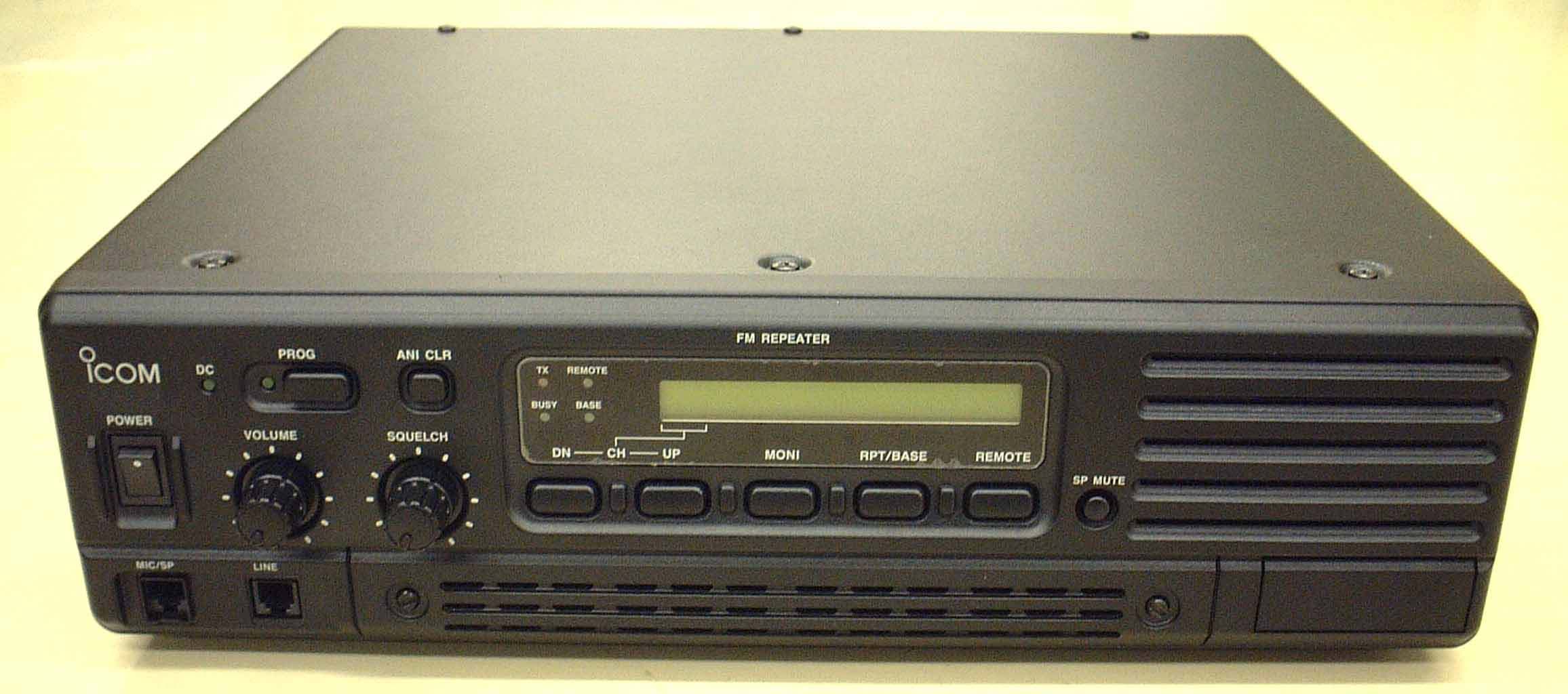
Click to zoom
Application Details
- Equipment Class
- TNB - Licensed Non-Broadcast Station Transmitter
- Date of Grant
- Jun 17, 2003
- Application Purpose
- Original Equipment
- Date of Application
- Jun 17, 2003
- Equipment Note
- VHF FM Repeater, Model ICFR3000
- Frequency Range
- 150.00000000 - 174.00000000
- Company
- ICOM Incorporated
- Country
- Japan
Documents & Files
Document Text
Text extracted from the exhibit documents filed with the FCC. Open a document above to read the original.
Users Manual
INSTRUCTION MANUAL VHF FM REPEATER iFR3000 UHF FM REPEATER iFR4000 i IMPORTANT READ THIS INSTRUCTION MANUAL CAREFULLYbefore attempting to operate the re- peater. SAVE THIS INSTRUCTION MANUAL–This manual contains important safety and operating in- structions for the IC-FR3000/FR4000 series. EXPLICIT DEFINITIONS RWARNING HIGH VOLTAGE! NEVERat- tach an antenna or internal antenna connector during transmission. This may result in an electrical shock or burn. RWARNING HIGH VOLTAGE! NEVERinstall the antenna at any place that person touch the an- tenna easily during transmission. This may result in an electrical shock or burn. RNEVERapply AC to the [BATTERY] terminals on the repeater rear panel. This could cause a fire or damage the repeater. RNEVERapply more than 16 V DC, such as a 24 V battery, to the [BATTERY] terminals on the repeater rear panel. This could cause a fire or damage the re- peater. RNEVERlet metal, wire or other objects touch any internal part or connectors on the rear panel of the re- peater. This may result in an electric shock. RNEVERexpose the repeater to rain, snow or any liquids. AVOIDusing or placing the repeater in areas with tem- peratures below –30°C (–22°F) or above +60°C (+140°F). Be aware that temperatures on a vehicle’s dashboard can exceed 80°C (+176°F), resulting in per- manent damage to the repeater if left there for ex- tended periods. AVOIDplacing the repeater in excessively dusty envi- ronments or in direct sunlight. AVOIDputting anything on top of the repeater. This will obstruct heat dissipation. Place the repeater in a secure place to avoid inadver- tent use by children. BE CAREFUL!The heatsink will become hot when op- erating the repeater continuously for long periods. BE CAREFUL!If a linear amplifier is connected, set the repeater’s RF output power to less than the linear amplifier’s maximum input level, otherwise, the linear amplifier will be damaged. Use Icom microphones only (optional). Other manu- facturer’s microphones have different pin assignments, and connection to the IC-FR3000/FR4000 series may damage the repeater. For U.S.A. only CAUTION:Changes or modifications to this repeater, not expressly approved by Icom Inc., could void your authority to operate this repeater under FCC regula- tions. CAUTION:This repeater is intended for use as a fixed base station with the antenna located outdoors on the rooftop or on antenna tower. PRECAUTION WORD R WARNING CAUTION NOTE DEFINITION Personal injury, fire hazard or electric shock may occur. Equipment damage may occur. If disregarded, inconvenience only. No risk of personal injury, fire or electric shock. Icom, Icom Inc. and the logo are registered trademarks of Icom Incorporated (Japan) in the United states, the United Kingdom, Germany, France, Spain, Russia and/or other coun- tries. ii For U.S.A. This equipment complies with the Federal Communi- cations Commission (FCC) rules and regulations gov- erning telephone equipment and the Technical Requirements for Connection to the Telephone Net- work published by the industry’s Administrative Council for Terminal Attachments (ACTA). On the right side of this equipment is a label that contains, among other in- formation, a product identifier in the format US:ICMOT03BIC-FR4000. If requested, this number must be provided to the telephone company. The applicable certification jack (connector) USOC-RJ- 11C is used for this equipment. This device can only be connected to the Public Switched Telephone Network (PSTN) using a tele- phone cord and modular plug that is compliant with the criteria adopted by the ACTA. This equipment is de- signed for connection to the telephone network or premises wiring using a compatible modular jack that is also compliant. The Ringer Equivalence Number (or REN) is used to determine the number of devices that may be con- nected to a telephone line. Excessive RENs on a tele- phone line may result in the devices not ringing in response to an incoming call. In most, but not all areas, the sum of RENs should not exceed five (5.0). To be certain of the number of devices that may be connected to a line, as determined by the total RENs, contact the local telephone company. The REN for this product is printed on the product identifier label CAUTION:If this equipment is deemed potentially harmful to the telephone network, the telephone com- pany will attempt to notify you in advance of discontin- uing service. If advance notice is not practical, the telephone company will notify you as soon as possi- ble. If service is disconnected, you will be advised of your right to file a complaint with the Federal Commu- nications Commission (FCC) should you believe it nec- essary. The telephone company may make changes in its fa- cilities, equipment, operations or procedures that could affect the operation of this equipment. Should this occur, advance notice you be provided in order for you to make necessary modifications to maintain uninter- rupted service. Should you experience trouble with this equipment, please contact: ICOM America, Technical Support at 425-454-7619 for repair or warranty information. If the equipment is causing harm to the telephone network, the telephone company may request that you discon- nect the equipment until the problem is resolved. There are no user serviceable parts for a telephone cir- cuit inside of this IC-FR3000 or IC-FR4000. NOTICE:Connection to party line service is subject to state tariffs. Contact the state public utility commission, public service commission or corporation commission for information. If your home has specially wired alarm equipment con- nected to the telephone line, ensure the installation of this IC-FR3000 or IC-FR4000 does not disable your alarm equipment. If you have questions about what will disable alarm equipment, consult your telephone com- pany or a qualified installer. For CANADA NOTICE:This equipment meets the applicable Indus- try Canada Terminal Equipment Technical Specifica- tions. …
Text truncated - open the document above for the full version.
Operational Description
IC-FR3000 VHF REPEATER CIRCUIT DESCRIPTION 1 RECEIVER CIRCUITS 1-1 RF CIRCUIT (RX UNIT) RF signals from the antenna connector pass through the tunable Band-pass filter (D3, L2, D4, L3) and then applied to the RF amplifier (Q1) after passing through the band-pass filter of 2 steps(C207,L6,C208,L7). Variable-capacitor diodes are employed at the band-pass filters that track the filters and Are controlled by CPU (LOGIC UNIT IC33) via the buffer IC (IC5). 1-2 1ST MIXER AND 1ST IF CIRCUIT (RX UNIT) The 1st mixer circuit(IC1) converts the received signals to a fixed frequency of the 1st IF signal with a 1st local output signal. By changing the PLL frequency, only the desired frequency will pass through the band-pass filter at the next stage of 1st mixer circuit. The RF signals are mixed with 1st LO signals at the 1st mixer (lC1) to produce a 31.65 MHZ 1st IF signal. The 1st IF signal is output from IC1 pin 4,5 and passed through the crystal band-pass filter (FI1) to suppress unwanted harmonic components. The filtered signal is amplified at the IF amplifier (Q3). The amplified signal is applied to the 2nd mixer and IF circuit (lC2). 1-3 2ND IF AND DEMODULATOR CIRCUITS (RX UNIT) The 2nd mixer circuit converts the 1st IF signal to a 2nd IF signal(455kHz). A double conversion super-heterodyne system (which converts receive signal twice) improves the image rejection ratio and obtains stable receiver gain The FM IC (lC2) contains the 2nd mixer, limiter and noise amplifiers, FM detector, active filter circuits, etc A 2nd LO signal (31.195 MHz). The 31.65 MHZ 1st IF signal from the IF amplifier (Q3) is applied to the 2nd mixer section of the FM IF IC (lC2, pin 16), and is mixed with the 2nd LO signal (31.195 MHz) to be converted to a 455 kHz 2nd IF signal. The 2nd IF signal is applied to the FM demodulator circuitsand passes through the ceramic band-pass filter (Fl5 or Fl6) The filtered signal is fed back to the IC, and amplified at the limiter amplifier section (pin 5) ,then demodulated into AF signals at the quadrature detector section (pins 10, 11). 1-4 AF AMPLIFIER CIRCUIT (LOGIC UNIT) The AF amplifier circuit amplifies the demodulated AF signals to drive a speaker. The AF signals pass through the AF mute switch (IC16), and are then applied to the volume control unit. The level controlled AF signals applied to the AF power amplifier. (lC17, pin 1) The power amplified AF signals are applied to the internal speaker (SP I ) via the [SP] jack (J9) therefore, the AF output level is according to the [VOL] setting and also the squelch conditions. 2 TRANSMITTER CIRCUITS 2-1 MICROPHONE AMPLIFIER CIRCUIT (LOGIC UNIT) The microphone signal from a FRONT unit is inputted into a LOGIC unit from J4. the inputted microphone signal - microphone amplifier (IC1D), MIX amplifier (IC2D) with other abnormal-conditions incoming signals, Pre-Emphasis (C2, R5, IC2C), HPF (IC2 B, A), a limiter (IC3A), MIX amplifier (IC3B) with signaling, and a Splatter filter (IC4A, B, C) - a passage - after that - TX unit -- it is led to an abnormal-conditions circuit. 2-2 REPEATER OPERATIONS (LOGIC UNIT) While a receiving AF signal (DISC) is led to a speaker output system at the time of relay AF Repeater operation, in order to process also as an abnormal-conditions signal, it is led to a D/A converter (IC25) through IC14. After being set as a suitable level by IC25, it goes to a limiter (IC3A). 5/2-TONE from Signaling (encoding) CPU, and a DTME output (IC33, pin 43) -- IC3 -- it is inputted into LPF, which consists of C and D It, is compounded with a voice signal by IC3B after that. CTCSS and a DTCS signal (IC33, pin 44) pass along LPF of IC4D, and are led to TX unit. TX IC6 compounds it with a voice signal, and abnormal conditions are simultaneously hung on VCO and a PLL standard oscillation. 2-3 DRIVE CIRCUITS (TX UNIT) / POWER AMPLIFIER CIRCUITS (PA UNIT) The RF signal from the TX VCO is amplified at the buffer amplifier (Q1), and is then applied to the pre-amplifier (PA UNT Q4). The amplified signal is amplified drive amplifier (PA UNIT IC2) is a power amplifier which provides stable 50 W output power with a 13.6 V DC power source. Output power amplified signal passes through the TX LPF (C98, L20, C2, L7, C3, L6, C1, C100, C48, C73),and is then applied to the SWR detector (D4). The LPF suppress high harmonics components. The signal is applied to the antenna connector after being passed through the reverse power detector circuit (D2) The detected voltage at the reverse detector circuit is applied to the CPU (LOGIC UNIT : lC33, pin 46/47) to switch from high power to low power automatically when the SWR become worse. 2-4 APC CIRCUIT (PA UNIT) The APC circuit protects the power amplifier (IC2) from a mismatched output load and stabilizes the RF power. The SWR detector circuit (D2) detects forward signals and reflection signals at D4 respectively. When antenna impedance is mismatched, the detected voltage exceeds the power setting voltage. The output voltage of the controls the power amplifier (IC2) to reduce the output power. 3 PLL CIRCUITS 3-1 GENERAL A PLL circuit provides stable oscillation of the transmit frequency and receive local frequency. The PLL circuit compares the phase of the divided VCO frequency to the reference frequency. The PLL output frequency is controlled by the divided ratio (N-data) of a programmable divider. 3-2 VCO CIRCUIT TX-VCO CIRCUIT (TX VCO UNIT) An oscillated signal from the TX-VCO circuit (Q1, D1-D4) passes through the buffer amplifiers (TX UNIT Q3) and TX PLL IC (TX UNIT lC2, pin 10) And is then pre-scaled in the PLL IC based on the divided ratio (N-data). The reference signal is generated at the reference oscillator (TX UNIT X1, 12.8MHz). The reference signal is also applied to the PLL IC. The PLL IC detects the out-of-step phase using the reference frequency and outputs it from pin 18,20. The output signal is passed through the loop filter and is then applied to the TX VCO circuit as lock voltage. RX-VC…
Text truncated - open the document above for the full version.
Test Report
June 12, 2003 ICOM Incorporated 1-1-32, Kamiminami Hirano-ku, Osaka Japan, 547-0003 Attn.: Mr. Takahasi Aoki Subject: Certification Testing in accordance with FCC CFR 47, Parts 2 and 90 (Subpart I) - Non-Broadcast Radio Transceivers Operating in the frequency bands 150 - 174 MHz (12.5 kHz and 25 kHz Channel Spacings). Product: VHF FM REPEATER Model: IC-FR3000 FCC ID: AFJ236702 Dear Mr. Aoki, The product sample has been tested in accordance with FCC CFR 47, Parts 2 and 90 (Subpart I) - Non-Broadcast Radio Transceivers Operating in the frequency bands 150 - 174 MHz (12.5 kHz and 25 kHz Channel Spacings), and the results and observation were recorded in the engineering report, Our File No.: ICOM- 063FCC90 Enclosed you will find copy of the engineering report. If you have any queries, please do not hesitate to contact us. Yours truly, Tri Minh Luu, P.Eng Vice President - Engineering Encl. UltraTech Group of Labs 3000 Bristol Circle, Oakville, Ontario, Canada L6H 6G4 Tel.: (905) 829-1570 Fax.: (905) 829-8050 Website: www.ultratech-labs.com Email: [email protected] 31040/SIT C-1376 46390-2049 200093-0 2 00-034 SL2-IN-E-1119R VHF FM REPEATER (150 - 174 MHz) Model No.: IC-FR3000 FCC ID: AFJ236702 Applicant: ICOM Incorporated 1-1-32, Kamiminami Hirano-ku, Osaka Japan, 547-0003 Tested in Accordance With Federal Communications Commission (FCC) CFR 47, PARTS 2 and 90 (Subpart I) UltraTech's File No.: ICOM-063FCC90 This Test report is Issued under the Authority of Tri M. Luu, Professional Engineer, Vice President of Engineering UltraTech Group of Labs Date: June 12, 2003 Report Prepared by: Tri M. Luu, P.Eng. Tested by: Wayne Wu, RFI Engineer Issued Date: June 12, 2003 Test Dates: May 28 - June 10, 2003 The results in this Test Report apply only to the sample(s) tested, and the sample tested is randomly selected. This report must not be used by the client to claim product endorsement by NVLAP or any agency of the US Government. UltraTech 3000 Bristol Circle, Oakville, Ontario, Canada, L6H 6G4 Tel.: (905) 829-1570 Fax.: (905) 829-8050 Website: www.ultratech-labs.com Email: [email protected], Email: [email protected] 2 31040/SIT C-1376 46390-2049 200093-0 SL2-IN-E-1119R 00-034 FCC PARTS 2 & 90, SUBPART I, NON-BROADCAST RADIO TRANSCEIVERS Page 1 VHF FM REPEATER, Model IC-FR3000 FCC ID: AFJ236702 ULTRATECH GROUP OF LABS File #: ICOM-063FCC90 3000 Bristol Circle, Oakville, Ontario, Canada L6H 6G4 June 12, 2003 Tel. #: 905-829-1570, Fax. #: 905-829-8050, Email: [email protected] , Website: http://www.ultratech-labs.com All test results contained in this engineering test report are traceable to National Institute of Standards and Technology (NIST) TABLE OF CONTENTS EXHIBIT 1. SUBMITTAL CHECK LIST........................................................................................................................ 3 EXHIBIT 2. INTRODUCTION ......................................................................................................................................... 4 2.1. SCOPE......................................................................................................................................................................... 4 2.2. RELATED SUBMITAL(S)/GRANT(S)................................................................................................................................. 4 2.3. NORMATIVE REFERENCES.................................................................................................................................... 4 EXHIBIT 3. PERFORMANCE ASSESSMENT............................................................................................................... 5 3.1. CLIENT INFORMATION ............................................................................................................................................. 5 3.2. EQUIPMENT UNDER TEST (EUT) INFORMATION...................................................................................................... 5 3.3. EUT’S TECHNICAL SPECIFICATIONS.................................................................................................................. 6 3.4. LIST OF EUT’S PORTS.................................................................................................................................................. 7 3.5. ANCILLARY EQUIPMENT............................................................................................................................................... 7 3.6. BLOCK DIAGRAM.................................................................................................................................................... 8 EXHIBIT 4. EUT OPERATING CONDITIONS AND CONFIGURATIONS DURING TESTS................................ 9 4.1. CLIMATE TEST CONDITIONS.......................................................................................................................................... 9 4.2. OPERATIONAL TEST CONDITIONS & ARRANGEMENT FOR TEST SIGNALS....................................................................... 9 EXHIBIT 5. SUMMARY OF TEST RESULTS ............................................................................................................. 10 5.1. LOCATION OF TESTS ............................................................................................................................................ 10 5.2. APPLICABILITY & SUMMARY OF EMISSION TEST RESULTS................................................................................... 10 5.3. MODIFICATIONS INCORPORATED IN THE EUT FOR COMPLIANCE PURPOSES.................................................................. 10 5.4. DEVIATION OF STANDARD TEST PROCEDURES ...........................................................................................10 EXHIBIT 6. MEASUREMENTS, EXAMINATIONS & TEST DATA FOR EMC EMISSIONS ............................. 11 6.1. TEST PROCEDURES.......................................................................…
Text truncated - open the document above for the full version.
Contact Information
Applicant
Atsushi Tomiyama(General Manager)
Technical Contact
Ultratech Engineering Labs Inc.Tri Luu
[email protected]905-829-1570
3000 Bristol Circle · Oakville · Canada
Technical Specifications
| # | Rule Parts | Frequency Range | Power Output | Emission | Tolerance |
|---|---|---|---|---|---|
| 4 | 9 | 150 MHz - 174 MHz | 50 W | 16K0F3E | 2.5 ppm |
Other Applications from ICOM Incorporated

AFJ453700
Jul 23, 2026Mobile Transceiver
Equipment Class
DTS - Digital Transmission System
AFJ452000
Jun 02, 2026VHF DIGITAL TRANSCEIVER
Equipment Class
TNF - Licensed Non-Broadcast Transmitter Held to Face
AFJ452100
May 12, 2026UHF DIGITAL TRANSCEIVER
Equipment Class
TNF - Licensed Non-Broadcast Transmitter Held to Face
AFJ444500
Sep 12, 2024Scanning Receiver
Equipment Class
CSR - Scanning Receiver
AFJ410900
Jul 09, 2024Linear Amplifier
Equipment Class
AMP - Amplifier