AFJ278800VHF/UHF Digital Transceiver
ICOM Incorporated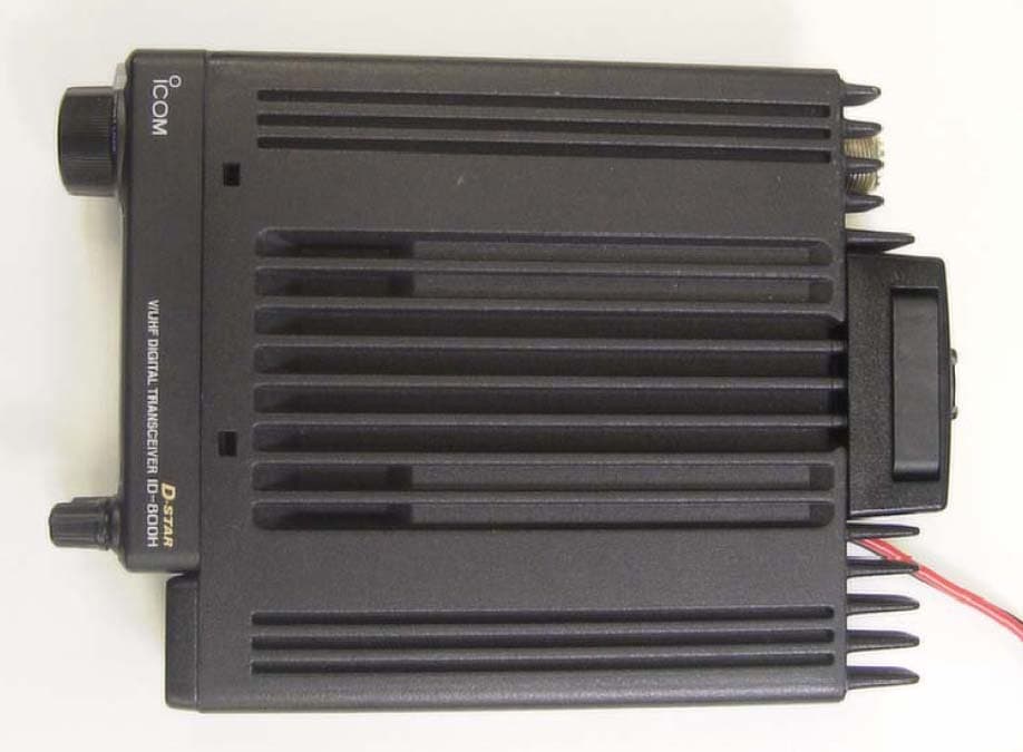
Click to zoom
Application Details
- Equipment Class
- CSR - Scanning Receiver
- Date of Grant
- Sep 27, 2004
- Application Purpose
- Original Equipment
- Date of Application
- Sep 27, 2004
- Equipment Note
- VHF/UHF Digital Transceiver
- Frequency Range
- 118.00000000 - 1000.00000000
- Company
- ICOM Incorporated
- Country
- Japan
Documents & Files
Document Text
Text extracted from the exhibit documents filed with the FCC. Open a document above to read the original.
Users Manual
INSTRUCTION MANUAL ID-800H VHF/UHF DIGITAL TRANSCEIVER This device complies with Part 15 of the FCC rules. Operation is sub- ject to the following two conditions: (1) This device may not cause harmful interference, and (2) this device must accept any interference received, including interference that may cause undesired operation. i FOREWORD Thank you for purchasing this Icom product. The ID-800H VHF/UHF DIGITAL TRANSCEIVERis designed and built with Icom’s state of the art technology and craftsmanship. With proper care, this product should provide you with years of trouble-free oper- ation. We want to take a couple of moments of your time to thank you for making your ID-800H your radio of choice, and hope you agree with Icom’s philosophy of “technology first.” Many hours of research and development went into the design of your ID-800H. DD FEATURES ❍Switchable VHF and UHF transceiver ❍Selectable backlit color from amber, green and yellow ❍Detachable controller for flexible installation ❍55 W* of high transmit output power *VHF band; 50 W for UHF band ❍Remote control microphone standard ❍New DMS (Dynamic Memory Scan) system IMPORTANT READ ALL INSTRUCTIONScarefully and completely before using the transceiver. SAVE THIS INSTRUCTION MANUAL—This in- struction manual contains important operating instructions for the ID-800H. EXPLICIT DEFINITIONS WORDDEFINITION RWARNING! CAUTION NOTE Personal injury, fire hazard or electric shock may occur. Equipment damage may occur. Recommended for optimum use. No risk of personal injury, fire or electric shock. Icom, Icom Inc. and the logo are registered trademarks of Icom Incorporated (Japan) in the United States, the United Kingdom, Ger- many, France, Spain, Russia and/or other countries. RWARNING RF EXPOSURE!This device emits Radio Frequency (RF) energy. Extreme caution should be observed when operating this device. If you have any questions regarding RF expo- sure and safety standards please refer to the Federal Communica- tions Commission Office of Engineering and Technology’s report on Evaluating Compliance with FCC Guidelines for Human Radio fre- quency Electromagnetic Fields (OET Bulletin 65). RWARNING! NEVERconnect the transceiver to an AC out- let. This may pose a fire hazard or result in an electric shock. RWARNING! NEVERoperate the transceiver while driving a vehicle. Safe driving requires your full attention—anything less may result in an accident. NEVERconnect the transceiver to a power source of more than 16 V DC. This will damage the transceiver. NEVERconnect the transceiver to a power source using reverse polarity. This will damage the transceiver. NEVERcut the DC power cable between the DC plug and fuse holder. If an incorrect connection is made after cutting, the transceiver may be damaged. NEVERexpose the transceiver to rain, snow or any liquids. The transceiver may be damaged. NEVERoperate or touch the transceiver with wet hands. This may result in an electric shock or damage the transceiver. NEVERplace the transceiver where normal operation of the vehi- cle may be hindered or where it could cause bodily injury. NEVERlet objects impede the operation of the cooling fan on the rear panel. DO NOTpush the PTT when not actually desiring to transmit. DO NOTallow children to play with any radio equipment contain- ing a transmitter. During mobile operation, DO NOToperate the transceiver with- out running the vehicle’s engine. When the transceiver’s power is ON and your vehicle’s engine is OFF, the vehicle’s battery will soon be- come exhausted. AVOIDusing or placing the transceiver in direct sunlight or in areas with temperatures below –10°C (+14°F) or above +60°C (+140°F). BE CAREFUL!The transceiver will become hot when operat- ing it continuously for long periods. AVOIDsetting the transceiver in a place without adequate venti- lation. Heat dissipation may be affected, and the transceiver may be damaged. AVOIDthe use of chemical agents such as benzine or alcohol when cleaning, as they can damage the transceiver’s surfaces. USEIcom microphones only (supplied or optional). Other manu- facturer’s microphones have different pin assignments and may dam- age the transceiver if attached. For U.S.A. only CAUTION:Changes or modifications to this device, not ex- pressly approved by Icom Inc., could void your authority to operate this device under FCC regulations. ii PRECAUTION iii TABLE OF CONTENTSSUPPLIED ACCESSORIES qDC power cable (3 m) .............................................1 wMobile mounting bracket .......................................1 eMicrophone (HM-133)* ..........................................1 rFuse (20 A) .........................................................1 tMounting screws, nuts and washers .....................1 set yMicrophone hanger ................................................1 uSeparation cable † (3.5 m; 11.5 ft) ..............................1 *HM-118N HAND MICROPHONEor HM-118TN/TAN DTMF MICROPHONE supplied versions are also available. † Aferrite core is adapted for the USA version. q w e r t y u FOREWORD ........................................................................................... i IMPORTANT ............................................................................................ i EXPLICIT DEFINITIONS ......................................................................... i PRECAUTION ........................................................................................ ii SUPPLIED ACCESSORIES .................................................................. iii TABLE OF CONTENTS ......................................................................... iii QUICK REFERENCE GUIDE ............................................................. I–X ■Installation ....................................................................................... I ■Your first contact .......................................................................... VII ■Repeater operation ...............................…
Text truncated - open the document above for the full version.
Users Manual
47 8 PRIORITY WATCH ■Priority watch operation qSelect VFO mode; then, set an operating frequency. wSet the watching channel(s). For memory channel watch: Select the desired memory channel. For memory scan watch: Select memory mode; then, push [V/MHz•SCAN] for 1 sec. to start memory scan. For call channel watch: Select the desired call channel by pushing [M/CALL•PRIO] once or twice, then push [BAND]. ePush [M/CALL•PRIO] for 1 sec. to start the watch. •The transceiver checks the memory or call channel every 5 sec. •The watch resumes according to the selected scan resume con- dition. (p. 45) •While the watch is pausing, pushing [M/CALL•PRIO] resumes the watch manually. rPush [M/CALL•PRIO] for 1 sec. to stop the watch. zSelect VFO mode; then, set the desired fre- quency. xSet the watching channel(s). For memory channel watch: Push [MR/CALL] then [Y] or [Z] to select the de- sired memory channel. For memory scan watch: Push [MR/CALL], then push [ SCAN2] to start the memory scan. For call channel watch: Push [MR/CALL] for 1 sec. then push [BAND] to select the call channel. cPush [ PRIO3(PTT-M)] to start the watch. •The transceiver checks the memory or call channel every 5 sec. •The watch resumes according to the selected scan re- sume condition. (p. 45) •To resume the watch manually when paused, push [PRIO3(PTT-M)] or [CLRA(MW)]. vTo stop the watch, push [CLRA(MW)] once (or twice while watch is paused). PRIO 3 48 9 DTMF MEMORY ENCODER 8 9 ■Programming a DTMF code DTMF tones are used for autopatching, controlling other equipment, etc. The transceiver has 16 DTMF memory chan- nels (D0–DF) for storage of often-used DTMF codes of up to 24 digits. qPush [MONI•DTMF] for 1 sec. to turn the DTMF encoder ON. •“d” appears in place of 100 MHz digit. wPush [SET•LOCK] to enter the DTMF memory program- ming condition. •The DTMF memory channel indication blinks. eRotate [DIAL] to select the desired DTMF memory chan- nel. rPush [SET•LOCK]. •The first digit blinks. tRotate [DIAL] to select the desired code. yPush [SET•LOCK] to select the next digit. •Pushing [S.MW•MW] moves the cursor backward. uRepeat the steps tand yto set the desired DTMF tone sequence. •The S/RF indicator shows the digit group. The indication in- creases every 6 digits. iPush [MONI•DTMF]to exit DTMF memory programming condition. •Return to the previous indication as in step q. [EXAMPLE]:Programming “5428AB453” into DTMF memory channel “D4.” Push Push then rotate Repeat the previous step until the desired code is entered. Push RotatePush for 1 sec. 49 9 DTMF MEMORY ENCODER D Programming a DTMF code— via microphone zPush [FUNC] then [LOW6(DTMF)] to turn the DTMF encoder ON. •“d” appears in place of 100 MHz digit. xPush [SETB(D-OFF)] to enter the DTMF memory programming condition. cPush [Y] or [Z] to select the desired DTMF memory channel. vPush the desired digit keys. •When the first digit is input, previous memory con- tents are cleared automatically. •“E” stands for “ MM ” and “F” stands for “# .” •Push [Y]/[Z] and repeat this step if you make a mistake. •The S/RF indicator shows the digit group. The indi- cation increases every 6 digits. bPush [VFO/LOCK] to exit the programming condition. •The [CLRA(MW)] key cannot be used to exit. If pushed, code “A” is input. Reprogram in such a case. DTMF [EXAMPLE]:Programming “5428AB453” into DTMF memory channel “D4.” Push Push Push Push Push then . 50 9 DTMF MEMORY ENCODER 9 ■Transmitting a DTMF code DAutomatic transmission (DTMF memory) qPush [MONI•DTMF] for 1 sec. to turn the DTMF memory encoder ON. • “d” appears in place of 100 MHz digit. wPush [SET•LOCK] to enter DTMF memory programming condition. eRotate [DIAL] to select the desired DTMF memory chan- nel. r Push [PTT] to transmit the selected DTMF memory content. tPush [MONI•DTMF] for 1 sec. to cancel the DTMF en- coder. •When the DTMF encoder is turned ON continuously, each push of the PTT transmits the previously selected DTMF code. zPush [FUNC] then [LOW6(DTMF)] to turn the DTMF memory encoder ON. •“d” appears in place of 100 MHz digit. xPush [SETB(D-OFF)] to enter the DTMF memory programming condition. cPush [Y] or [Z] to select the desired channel. vPush [PTT] to transmit the selected memory. •Exit the programming condition automatically. •Each push of [PTT] transmits the DTMF code. bPush [FUNC] then [SETB(D-OFF)] to cancel the DTMF memory encoder. •When the DTMF encoder is turned ON continuously, each push of the PTT transmits the previously se- lected DTMF code. DTransmitting a DTMF memory directly zPush [FUNC] then [LOW6(DTMF)] to turn the DTMF memory encoder ON. •“d” appears in place of 100 MHz digit. xPush [DTMF-S] to turn the DTMF memory di- rect selection ON. •The function indicator (microphone) lights green. cPush the desired DTMF channel. •“0” to “9” and “A” to “D” are available for DTMF memory channels. •The selected DTMF code is automatically transmit- ted without pushing PTT. NOTE:When no DTMF code programmed channel number is pushed, it transmits the rela- tive DTMF code as the manual transmission de- scribed in the next page. vPush [DTMF-S] again to deactivate the DTMF memory direct selection. bPush [FUNC] then [ SETB(D-OFF)] to cancel the DTMF memory encoder. DTMF-S DTMF 51 9 DTMF MEMORY ENCODER DManual transmission zDeactivate the DTMF memory encoder by pushing [FUNC] then [ SETB(D-OFF)]. x Push [DTMF-S] to turn the DTMF direct selec- tion ON. •The function indicator (microphone) lights green. cPush one of “0” to “9” and “A” to “F” keys mo- mentarily, then push the desired DTMF keys, 0–9 and A to F. •A: [CLRA(MW)]B: [SETB(D-OFF)], C: [ENTC(T-OFF)]D: [SQLYD(MUTE)], E: [ MM (TONE-1)]F: [SQLZ#(16KEY-L)] •Automatically transmits without pushing PTT. •The first code, one of “0” to “9” and “A” to “F,” is not transmitted. DTMF code transmission starts from the 2nd code. vPush [DTMF-S] again to deactivate the DTMF direct selection. ■DTMF speed The rate at which DTMF memories send individual DTMF characters can be set to accommodate …
Text truncated - open the document above for the full version.
Cover Letter(s)
September 23, 2004 AmericanTCB, Inc. 6731 Whittier Avenue, Suite C110 McLean, VA 22101 Subject: Certification Testing in accordance with FCC CFR 47, Part 15, Subpart B - Scanning Receiver operating in the frequency band 118- 1000 MHz. Product: VHF/UHF DIGITAL TRANSCEIVER Model No.: ID-800H FCC ID: AFJ278800 Dear Sir/Madam As appointed agent for ICOM Incorporated, we would like to submit the application for FCC certification of the above product. Please review all files uploaded to AmericanTCB electronic filing site. If you have any queries, please do not hesitate to contact us. Yours truly, Tri Minh Luu, P. Eng., V.P., Engineering Encl UltraTech Group of Labs 31040/SIT C-1376 46390-2049 200093-0 2 00-034 SL2-IN-E-1119R 3000 Bristol Circle, Oakville, Ontario, Canada L6H 6G4 Tel.: (905) 829-1570 Fax.: (905) 829-8050 Website: www.ultratech-labs.com Email: [email protected]
External Photos
ANNEX 2 – EXTERNAL EUT PHOTOS ICOM Incorporated VHF/UHF Digital Transceiver, Model ID-800H FCC ID: AFJ278800 A2 - 1 ANNEX 2 – EXTERNAL EUT PHOTOS ICOM Incorporated VHF/UHF Digital Transceiver, Model ID-800H FCC ID: AFJ278800 A2 - 2 ANNEX 2 – EXTERNAL EUT PHOTOS ICOM Incorporated VHF/UHF Digital Transceiver, Model ID-800H FCC ID: AFJ278800 A2 - 3 ANNEX 2 – EXTERNAL EUT PHOTOS ICOM Incorporated VHF/UHF Digital Transceiver, Model ID-800H FCC ID: AFJ278800 A2 - 4 ANNEX 2 – EXTERNAL EUT PHOTOS ICOM Incorporated VHF/UHF Digital Transceiver, Model ID-800H FCC ID: AFJ278800 A2 - 5 ANNEX 2 – EXTERNAL EUT PHOTOS ICOM Incorporated VHF/UHF Digital Transceiver, Model ID-800H FCC ID: AFJ278800 A2 - 6
Test Report
VHF/UHF DIGITAL TRANSCEIVER Model No.: ID-800H FCC ID: AFJ278800 Applicant: ICOM Incorporated 1-1-32, Kamiminami Hirano-ku, Osaka Japan, 547-003 Tested in Accordance With Federal Communications Commission (FCC) 47 CFR, Part 15, Subpart B Scanning Receiver Operating in the Frequency Band 118 - 1000 MHz UltraTech's File No.: ICOM-093FCC15RX This Test report is Issued under the Authority of Tri M. Luu, Professional Engineer, Vice President of Engineering UltraTech Group of Labs Date: September 23, 2004 Report Prepared by: Dharmajit Solanki, RFI Engineer Issued Date: September 23, 2004 Tested by: Wayne Wu, RFI Engineer Test Dates: August 13 – Sept. 22, 2004 The results in this Test Report apply only to the sample(s) tested, and the sample tested is randomly selected. This report must not be used by the client to claim product endorsement by NVLAP or any agency of the US Government. UltraTech 3000 Bristol Circle, Oakville, Ontario, Canada, L6H 6G4 Tel.: (905) 829-1570 Fax.: (905) 829-8050 Website: www.ultratech-labs.com , Email: [email protected], Email: [email protected] 2 31040/SIT C-1376 46390-2049 200093-0 SL2-IN-E-1119R 00-034 FCC PART 15, SUBPART B, SCANNING RECEIVER Page 1 VHF/UHF DIGITAL TRANSCEIVER, Model ID-800H FCC ID: AFJ278800 ULTRATECH GROUP OF LABS File #: ICOM-093FCC15RX 3000 Bristol Circle, Oakville, Ontario, Canada L6H 6G4 September 23, 2004 Tel.: 905-829-1570, Fax. : 905-829-8050 All test results contained in this engineering test report are traceable to National Institute of Standards and Technology (NIST) TABLE OF CONTENTS EXHIBIT 1. SUBMITTAL CHECK LIST..................................................................................................................... 2 EXHIBIT 2. INTRODUCTION ...................................................................................................................................... 3 2.1. SCOPE...................................................................................................................................................................... 3 2.2. RELATED SUBMITTAL(S)/GRANT(S) ............................................................................................................... 3 2.3. NORMATIVE REFERENCES ................................................................................................................................ 3 EXHIBIT 3. PERFORMANCE ASSESSMENT ........................................................................................................... 4 3.1. CLIENT INFORMATION ....................................................................................................................................... 4 3.2. EQUIPMENT UNDER TEST (EUT) INFORMATION .........................................................................................4 3.3. EUT’S TECHNICAL SPECIFICATIONS .............................................................................................................. 5 3.4. LIST OF EUT’S PORTS.......................................................................................................................................... 5 3.5. ANCILLARY EQUIPMENT ................................................................................................................................... 6 3.6. BLOCK DIAGRAM OF TEST SETUP................................................................................................................... 7 EXHIBIT 4. EUT OPERATING CONDITIONS AND CONFIGURATIONS DURING TESTS ............................ 6 4.1. CLIMATE TEST CONDITIONS ............................................................................................................................ 6 4.2. OPERATIONAL TEST CONDITIONS & ARRANGEMENT FOR TEST SIGNALS.......................................... 6 EXHIBIT 5. SUMMARY OF TEST RESULTS ............................................................................................................ 7 5.1. LOCATION OF TESTS........................................................................................................................................... 7 5.2. APPLICABILITY & SUMMARY OF EMC EMISSION TEST RESULTS .......................................................... 7 5.3. MODIFICATIONS REQUIRED FOR COMPLIANCE..........................................................................................7 EXHIBIT 6. MEASUREMENTS, EXAMINATIONS & TEST DATA FOR EMC EMISSIONS............................ 8 6.1. TEST PROCEDURES.............................................................................................................................................. 8 6.2. MEASUREMENT UNCERTAINTIES ................................................................................................................... 8 6.3. MEASUREMENT EQUIPMENT USED ................................................................................................................ 8 6.4. ESSENTIAL/PRIMARY FUNCTIONS AS DECLARED BY THE MANUFACTURER..................................... 8 6.5. RECEIVER ANTENNA POWER SPURIOUS/HARMONIC CONDUCTED EMISSIONS [47 CFR 15.111(A)]9 6.6. RECEIVER SPURIOUS/HARMONIC RADIATED EMISSIONS [47 CFR 15.109(A)] .................................... 14 6.7. RADIATED EMISSIONS FROM CLASS B UNINTENTIONAL RADIATION (DIGITAL DEVICE) [47 CFR 15.109 (A)] ............................................................................................................................................................. 16 6.8. REQUIREMENTS FOR SCANNING RECEIVER [47 CFR 15.121] .................................................................. 17 6.9. SCANNING RECEIVER CELLULAR BAND REJECTION [47 CFR 15.121(B)] ............................................. 20 EXHIBIT 7. MEASUREMENT UNCERTAINTY...................................................................................................... 22 7.1. LINE CONDUCTED EMISSION MEASUREMENT UNCERTAINTY ............................................................. 22 7.2. RADIATED EMI…
Text truncated - open the document above for the full version.
Test Setup Photos
ANNEX 1 - TEST SETUP PHOTOS ICOM Incorporated VHF/UHF Digital Transceiver, Model ID-800H FCC ID: AFJ278800 A1 - 1 Radiated Emissions at 3 Meters ANNEX 1 - TEST SETUP PHOTOS ICOM Incorporated VHF/UHF Digital Transceiver, Model ID-800H FCC ID: AFJ278800 A1 - 2 Radiated Emissions at 3 Meters
Contact Information
Applicant
Atsushi Tomiyama(General Manager)
Technical Contact
Ultratech Engineering Labs Inc.Tri Luu
[email protected]905-829-1570
3000 Bristol Circle · Oakville · Canada
Test Firm
UltraTech Engineering Labs Inc.Tri Luu
Technical Specifications
| # | Rule Parts | Frequency Range | Power Output |
|---|---|---|---|
| 1 | 15B | 118 MHz - 1.00 GHz | - |
Other Applications from ICOM Incorporated

AFJ453700
Jul 23, 2026Mobile Transceiver
Equipment Class
DTS - Digital Transmission System
AFJ452000
Jun 02, 2026VHF DIGITAL TRANSCEIVER
Equipment Class
TNF - Licensed Non-Broadcast Transmitter Held to Face
AFJ452100
May 12, 2026UHF DIGITAL TRANSCEIVER
Equipment Class
TNF - Licensed Non-Broadcast Transmitter Held to Face
AFJ444500
Sep 12, 2024Scanning Receiver
Equipment Class
CSR - Scanning Receiver
AFJ410900
Jul 09, 2024Linear Amplifier
Equipment Class
AMP - Amplifier