AFJ282600VHF Scanning Receiver
ICOM Incorporated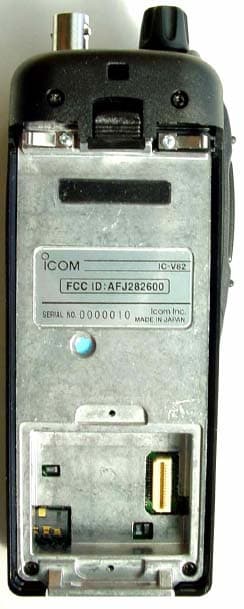
Click to zoom
Application Details
- Equipment Class
- CSR - Scanning Receiver
- Date of Grant
- Nov 07, 2004
- Application Purpose
- Original Equipment
- Date of Application
- Nov 07, 2004
- Equipment Note
- VHF Scanning Receiver
- Frequency Range
- 136.00000000 - 174.00000000
- Company
- ICOM Incorporated
- Country
- Japan
Documents & Files
Document Text
Text extracted from the exhibit documents filed with the FCC. Open a document above to read the original.
Users Manual
INSTRUCTION MANUAL iV82 VHF TRANSCEIVER This device complies with Part 15 of the FCC rules. Operation is sub- ject to the following two conditions: (1) This device may not cause harmful interference, and (2) this device must accept any interference received, including interference that may cause undesired operation. FOREWORD Thank you for purchasing this Icom product. The IC-V82 VHF TRANSCEIVER is designed and built with Icom’s superior tech- nology and craftsmanship. With proper care, this product should provide you with years of trouble-free operation. We want to take a couple of moments of your time to thank you for making your IC-V82 your radio of choice, and hope you agree with Icom’s philosophy of “technology first.” Many hours of research and development went into the design of your IC-V82. DD FEATURES ❍7W of high transmit output power ❍CTCSS and DTCS encoder/decoder stan- dard ❍Optional Digital modulator/demodulator ❍Optional DTMF decoder ❍MIL-STD810 grade durability IMPORTANT READ ALL INSTRUCTIONScarefully and completely before using the transceiver. SAVE THIS INSTRUCTION MANUAL—This in- struction manual contains important operating instructions for the IC-V82. EXPLICIT DEFINITIONS WORDDEFINITION RWARNING! CAUTION NOTE Personal injury, fire hazard or electric shock may occur. Equipment damage may occur. Recommended for optimum use. No risk of personal injury, fire or electric shock. Icom, Icom Inc. and the logo are registered trademarks of Icom Incorporated (Japan) in the United States, the United Kingdom, Ger- many, France, Spain, Russia and/or other countries. i ii RWARNING! NEVERhold the transceiver so that the antenna is very close to, or touching exposed parts of the body, especially the face or eyes, while transmitting. The transceiver will perform best if the microphone is 5 to 10 cm (2 to 4 inches) away from the lips and the transceiver is verti- cal. RWARNING! NEVERoperate the transceiver with a headset or other audio accessories at high volume levels. Hearing experts advise against continuous high volume op- eration. If you experience a ringing in your ears, reduce the volume or discontinue use. NEVERconnect the transceiver to a power source that is DC fused at more than 5 A. Accidental reverse connection will be protected by this fuse, but higher fuse values will not give any protection against such accidents and the transceiver will be ruined. NEVERattempt to charge alkaline or dry cell batteries. Be aware that external DC power connections will charge batter- ies inside the battery case. This will damage not only the bat- tery case but also the transceiver. DO NOTpush the PTT when not actually desiring to trans- mit. Place the unit in a secure place to avoid inadvertent use by children. DO NOToperate the transceiver near unshielded electrical blasting caps or in an explosive atmosphere. AVOIDusing or placing the transceiver in direct sunlight or in areas with temperatures below –10°C (+14 ̊F) or above +60°C (+140 ̊F). The use of non-Icom battery packs/chargers may impair transceiver performance and invalidate the warranty. Even when the transceiver power is OFF, a slight current still flows in the circuits. Remove the battery pack or case from the transceiver when not using it for a long time. Otherwise, the battery pack or installed Ni-Cd batteries will become ex- hausted. For USA only: Caution: Changes or modifications to this transceiver, not ex- pressly approved by Icom Inc., could void your authority to operate this transceiver under FCC regulations. PRECAUTION iii SUPPLIED ACCESSORIES ■Supplied Accessories qAntenna* . . . . . . . . . . . . . . . . . . . . . . . . . . . . . . . . . . . . . 1 wBelt clip (with screws) . . . . . . . . . . . . . . . . . . . . . . . . . . . 1 eAC Adapter . . . . . . . . . . . . . . . . . . . . . . . . . . . . . . . . . . . 1 rBattery pack*/Battery case* . . . . . . . . . . . . . . . . . . . . . . 1 tBattery charger*. . . . . . . . . . . . . . . . . . . . . . . . . . . . . 1 set *Not supplied with some versions. e q w r t iv CAUTION To ensure that your exposure to RF electromagnetic en- ergy is within the FCC allowable limits, always adhere to the following guidelines: • DO NOToperate the radio without a proper antenna at- tached, as this may damage the radio and may also cause you to exceed FCC RF exposure limits. A proper antenna is the antenna supplied with this radio by the manufacturer or an antenna specifically authorized by the manufacturer for use with this radio. • DO NOTtransmit for more than 50% of total radio use time (“50% duty cycle”). Transmitting more than 50% of the time can cause FCC RF exposure compliance requirements to be exceeded. The radio is transmitting when the “TX indica- tor” is lit. You can cause the radio to transmit by pressing the “PTT” switch. • ALWAYSuse Icom authorized accessories (antennas, bat- teries, belt clips, speaker/mics, etc.). Use of unauthorized accessories can cause the FCC RF exposure compliance requirements to be exceeded. • ALWAYSkeep the antenna at least 2.5 cm (1 inch) away from the body when transmitting, and only use the Icom belt-clips which are listed in this manual when attaching the radio to your belt, etc. To provide the recipients of your transmission the best sound quality, hold the antenna at least 5 cm (2 inches) from your mouth, and slightly off to one side. The information listed above provides the user with the information needed to make him or her aware of RF ex- posure, and what to do to assure that this radio operates within the FCC RF exposure limits of this radio. Electro- magnetic Interference/Compatibility. During transmis- sions, your Icom radio generates RF energy that can possibly cause interference with other devices or sys- tems. To avoid such interference, turn off the radio in areas where signs are posted to do so. DO NOT operate the transmitter in areas that are sensitive to electromag- netic radiation such as hospitals, aircraft, and blasting sites. SAF…
Text truncated - open the document above for the full version.
Users Manual
31 8 SCAN OPERATION 8 DMemory scan watch While operating on a VFO frequency or the call channel, mem- ory scan watch monitors for signals in each memory channel in sequence, every 5 sec. qPush [C• MR]to select memory mode, if necessary. •“X” appears. wPush [A•FUNC], then push [5•SCAN]to start the memory scan. ePush [A• FUNC], then push [7•PRIO]to start the watching. •VFO is displayed, then the decimal point “.”, on the frequency readout blinks. • When the signal is detected on the priority channel, the watching is paused according to the setting of the scan resume condition. rPush [D•CLR]to stop the watching. ■Scan resume condition When a signal is received during scanning, the scan resume condition determines what action the transceiver takes. The transceiver has 2 scan resume conditions available as illustrated below. Use SET MODEto select the one which best suits your needs. qPush [A• FUNC], then push [8•SET]to enter SET MODE. wPush [ YY ]or [ ZZ ]several times until “SCP” or “SCt” ap- pears. eRotate [VOL]to select the desired scan resume condition. •Pause scan: When receiving a signal, scan pauses on the signal until it disappears. Resumes 2 sec. after the signal disappears. •Timer scan: When receiving a signal, scan pauses on the signal for 5 sec., 10 sec. or 15 sec., then resumes. rPush [✱•ENT](or [D•CLR])to set and exit SET MODE. Timer scan Pause scan USINGSET MODE ■Tone squelch DOperation The tone squelch opens only when receiving a signal con- taining a matching subaudible tone. You can silently wait for calls from group members using the same tone. qSet the operating frequency. • Set the AF and squelch to the desired level as the normal opera- tion. wSet the desired subaudible tone in SET MODE. • See page 32 for programming. ePush [A•FUNC], then push [1•TONE]. •Repeat several times until “ ” appears when selecting CTCSS, or “ ” appears when selecting DTCS. rWhen the received signal includes a matching tone, squelch opens and the signal can be heard. • When the received signal’s tone does not match, tone squelch does not open, however, the S-indicator shows signal strength. • To open the squelch manually, push and hold [MONI]. tOperate the transceiver in the normal way. yTo cancel the tone squelch, push [A• FUNC]and [1•TONE]. •Repeat several times until “ ” or “ ” disappears. NOTE:The transceiver has 50 tone frequencies and con- sequently their spacing is narrow compared to units having 38 tones. Therefore, some tone frequencies may receive interference from adjacent tone frequencies. To prevent interference from adjacent tone frequencies, using the frequencies as in the following table, is recom- mended. • Recommended tone frequencies(Unit: Hz) 67.0 69.3 71.9 74.4 77.0 94.8 97.4 100.0 103.5 107.2 131.8 136.5 141.3 146.2 151.4 186.2 192.8 203.5 210.7 218.1 79.7 82.5 85.4 88.5 91.5 110.9 114.8 118.8 123.0 127.3 156.7 162.2 167.9 173.8 179.9 225.7 233.6 241.8 250.3 D Push FUNC A TONE 1 CTCSSDTCS D 32 SUBAUDIBLE TONES 9 33 9 SUBAUDIBLE TONES 9 Separate tone frequencies can be set for tone squelch oper- ation rather than repeater operation (the same range of tones is available— see right below). Like the repeater tones, these are set in SET MODE. qSelect VFO or memory channel. wPush [A• FUNC], then push [8•SET]to enter SET MODE. ePush [ YY ]or [ ZZ ]several times until “Ct” appears when se- lecting CTCSS, or “dt” appears when selecting DTCS. •“” blinks when selecting CTCSS, or “ ” blinks when selecting DTCS. rRotate [VOL]to select the desired subaudible tone. tPush [✱• ENT](or [D•CLR]) to program the selected tone and exit SET MODE. When SET MODEis selected from memory mode. yPush [A• FUNC], then push [C•MR]for 1 sec. to transfer the contents to VFO. •3 beeps are emitted. •VFO mode is selected automatically. uPush [A•FUNC], then push [C•MR]for 1 sec. •3 beeps are emitted. Steps yand uare necessary when overwriting the memory contents permanently. The set tone frequency is used for temporary operation only, therefore, these steps are not nec- essary. •Available CTCSS tone frequency list(unit: Hz) 67.0 69.3 71.9 74.4 77.0 85.4 88.5 91.5 94.8 97.4 100.0 103.5 79.7 82.5 107.2 110.9 114.8 118.8 123.0 127.3 131.8 136.5 141.3 146.2 151.4 156.7 159.8 162.2 165.5 167.9 171.3 173.8 177.3 179.9 183.5 186.2 189.9 192.8 196.6 199.5 203.5 206.5 210.7 218.1 225.7 229.1 233.6 241.8 250.3 254.1 D DSetting subaudible tones for tone squelch operation 34 9 SUBAUDIBLE TONES ■Pocket beep operation This function uses subaudible tones for calling and can be used as a “common pager” to inform you that someone has called when you were away from the transceiver. DWaiting for a call from a specific station qSet the operating frequency. wSet the desired CTCSS tone frequency or DTCS code in SET MODE. • See p. 33 for programming details. ePush [A•FUNC], then push [1•TONE]. •Repeat several times until “ ” appears when CTCSS, or “ ” ap- pears when DTCS is selected. rPush [A•FUNC], then push [2•P.BEEP]to activate the pocket beep function. •“” appears. tWhen a signal with the matched tone is received, the transceiver emits beep tones and blinks “ .” • Beep tones sound for 30 sec. and “ ” blinks. To stop the beeps manually, push any key. “ ” continues blinking until step yis operated. yPush [PTT]to answer. • “ ” disappears and cancels the pocket beep function automati- cally. CTCSSDTCS Push FUNC A P.BEEP 2 CTCSSDTCS Push FUNC A TONE 1 CTCSSDTCS D 35 9 SUBAUDIBLE TONES 9 ■Tone scan By monitoring a signal that is being operated with a repeater, pocket beep or tone squelch function, you can determine the tone frequency necessary to access a repeater or open the squelch. qSet the frequency to be checked for a tone frequency or code. wPush [A• FUNC], then push [1•TONE]. •Repeat several times to select the tone condition or type to be scanned. (One of “ ,” “ ” or “ ” appears) •The tone scan can be operated even if the tone condition or type is not selected. ePush [A•FUNC], then push [3•T.SCAN]to start the tone scan. • To ch…
Text truncated - open the document above for the full version.
External Photos
ANNEX 2 – EXTERNAL EUT PHOTOS ICOM Incorporated VHF Transceiver, Model IC-V82 FCC ID: AFJ282600 A2 - 1 ANNEX 2 – EXTERNAL EUT PHOTOS ICOM Incorporated VHF Transceiver, Model IC-V82 FCC ID: AFJ282600 A2 - 2 ANNEX 2 – EXTERNAL EUT PHOTOS ICOM Incorporated VHF Transceiver, Model IC-V82 FCC ID: AFJ282600 A2 - 3 ANNEX 2 – EXTERNAL EUT PHOTOS ICOM Incorporated VHF Transceiver, Model IC-V82 FCC ID: AFJ282600 A2 - 4 ANNEX 2 – EXTERNAL EUT PHOTOS ICOM Incorporated VHF Transceiver, Model IC-V82 FCC ID: AFJ282600 A2 - 5 ANNEX 2 – EXTERNAL EUT PHOTOS ICOM Incorporated VHF Transceiver, Model IC-V82 FCC ID: AFJ282600 A2 - 6 ANNEX 2 – EXTERNAL EUT PHOTOS ICOM Incorporated VHF Transceiver, Model IC-V82 FCC ID: AFJ282600 A2 - 7
Test Report
VHF TRANSCEIVER Model No.: IC-V82 FCC ID: AFJ282600 Applicant: ICOM Incorporated 1-1-32, Kamiminami Hirano-ku, Osaka Japan, 547-003 Tested in Accordance With Federal Communications Commission (FCC) 47 CFR, Part 15, Subpart B Scanning Receiver Operating in the Frequency Band 136 - 174 MHz UltraTech's File No.: ICOM-097FCC15RX This Test report is Issued under the Authority of Tri M. Luu, Professional Engineer, Vice President of Engineering UltraTech Group of Labs Date: November 1, 2004 Report Prepared by: Dharmajit Solanki, RFI Engineer Issued Date: November 1, 2004 Tested by: Wayne Wu, RFI Engineer Test Dates: October 7 - 15, 2004 The results in this Test Report apply only to the sample(s) tested, and the sample tested is randomly selected. This report must not be used by the client to claim product endorsement by NVLAP or any agency of the US Government. UltraTech 3000 Bristol Circle, Oakville, Ontario, Canada, L6H 6G4 Tel.: (905) 829-1570 Fax.: (905) 829-8050 Website: www.ultratech-labs.com , Email: [email protected], Email: [email protected] 2 31040/SIT C-1376 46390-2049 200093-0 SL2-IN-E-1119R 00-034 FCC PART 15, SUBPART B, SCANNING RECEIVER Page 1 VHF TRANSCEIVER, Model IC-V82 FCC ID: AFJ282600 ULTRATECH GROUP OF LABS File #: ICOM-097FCC15RX 3000 Bristol Circle, Oakville, Ontario, Canada L6H 6G4 November 1, 2004 Tel.: 905-829-1570, Fax. : 905-829-8050 All test results contained in this engineering test report are traceable to National Institute of Standards and Technology (NIST) TABLE OF CONTENTS EXHIBIT 1. SUBMITTAL CHECK LIST..................................................................................................................... 2 EXHIBIT 2. INTRODUCTION ...................................................................................................................................... 3 2.1. SCOPE...................................................................................................................................................................... 3 2.2. RELATED SUBMITTAL(S)/GRANT(S) ............................................................................................................... 3 2.3. NORMATIVE REFERENCES ................................................................................................................................ 3 EXHIBIT 3. PERFORMANCE ASSESSMENT ........................................................................................................... 4 3.1. CLIENT INFORMATION ....................................................................................................................................... 4 3.2. EQUIPMENT UNDER TEST (EUT) INFORMATION .........................................................................................4 3.3. EUT’S TECHNICAL SPECIFICATIONS .............................................................................................................. 5 3.4. LIST OF EUT’S PORTS.......................................................................................................................................... 5 3.5. ANCILLARY EQUIPMENT ................................................................................................................................... 5 3.6. BLOCK DIAGRAM OF TEST SETUP................................................................................................................... 6 EXHIBIT 4. EUT OPERATING CONDITIONS AND CONFIGURATIONS DURING TESTS ............................ 6 4.1. CLIMATE TEST CONDITIONS ............................................................................................................................ 6 4.2. OPERATIONAL TEST CONDITIONS & ARRANGEMENT FOR TEST SIGNALS.......................................... 6 EXHIBIT 5. SUMMARY OF TEST RESULTS ............................................................................................................ 7 5.1. LOCATION OF TESTS........................................................................................................................................... 7 5.2. APPLICABILITY & SUMMARY OF EMC EMISSION TEST RESULTS .......................................................... 7 5.3. MODIFICATIONS REQUIRED FOR COMPLIANCE..........................................................................................7 EXHIBIT 6. MEASUREMENTS, EXAMINATIONS & TEST DATA FOR EMC EMISSIONS............................ 8 6.1. TEST PROCEDURES.............................................................................................................................................. 8 6.2. MEASUREMENT UNCERTAINTIES ................................................................................................................... 8 6.3. MEASUREMENT EQUIPMENT USED ................................................................................................................ 8 6.4. ESSENTIAL/PRIMARY FUNCTIONS AS DECLARED BY THE MANUFACTURER..................................... 8 6.5. RECEIVER ANTENNA POWER SPURIOUS/HARMONIC CONDUCTED EMISSIONS [47 CFR 15.111(A)]9 6.6. RECEIVER SPURIOUS/HARMONIC RADIATED EMISSIONS [47 CFR 15.109(A)] .................................... 13 6.7. RADIATED EMISSIONS FROM CLASS B UNINTENTIONAL RADIATION (DIGITAL DEVICE) [47 CFR 15.109 (A)] ............................................................................................................................................................. 15 6.8. REQUIREMENTS FOR SCANNING RECEIVER [47 CFR 15.121] .................................................................. 16 6.9. SCANNING RECEIVER CELLULAR BAND REJECTION [47 CFR 15.121(B)] ............................................. 19 EXHIBIT 7. MEASUREMENT UNCERTAINTY...................................................................................................... 21 7.1. LINE CONDUCTED EMISSION MEASUREMENT UNCERTAINTY ............................................................. 21 7.2. RADIATED EMISSION MEASUREMENT UNCERTAINTY .........…
Text truncated - open the document above for the full version.
Test Setup Photos
ANNEX 1 - TEST SETUP PHOTOS ICOM Incorporated VHF Transceiver, Model IC-V82 FCC ID: AFJ282600 A1 - 1 Radiated Emissions at 3 Meters (Orthogonal Position 1) ANNEX 1 - TEST SETUP PHOTOS ICOM Incorporated VHF Transceiver, Model IC-V82 FCC ID: AFJ282600 A1 - 2 Radiated Emissions at 3 Meters (Orthogonal Position 2) ANNEX 1 - TEST SETUP PHOTOS ICOM Incorporated VHF Transceiver, Model IC-V82 FCC ID: AFJ282600 A1 - 3 Radiated Emissions at 3 Meters (Orthogonal Position 3) ANNEX 1 - TEST SETUP PHOTOS ICOM Incorporated VHF Transceiver, Model IC-V82 FCC ID: AFJ282600 A1 - 4 Radiated Emissions at 3 Meters (Back View)
Contact Information
Applicant
Atsushi Tomiyama(General Manager)
Technical Contact
Ultratech Engineering Labs Inc.Tri Luu
[email protected]905-829-1570
3000 Bristol Circle · Oakville · Canada
Test Firm
UltraTech Engineering Labs Inc.Tri Luu
Technical Specifications
| # | Rule Parts | Frequency Range | Power Output |
|---|---|---|---|
| 1 | 15B | 136 MHz - 174 MHz | - |
Other Applications from ICOM Incorporated

AFJ453700
Jul 23, 2026Mobile Transceiver
Equipment Class
DTS - Digital Transmission System
AFJ452000
Jun 02, 2026VHF DIGITAL TRANSCEIVER
Equipment Class
TNF - Licensed Non-Broadcast Transmitter Held to Face
AFJ452100
May 12, 2026UHF DIGITAL TRANSCEIVER
Equipment Class
TNF - Licensed Non-Broadcast Transmitter Held to Face
AFJ444500
Sep 12, 2024Scanning Receiver
Equipment Class
CSR - Scanning Receiver
AFJ410900
Jul 09, 2024Linear Amplifier
Equipment Class
AMP - Amplifier