AFJ287900Communication Receiver
ICOM Incorporated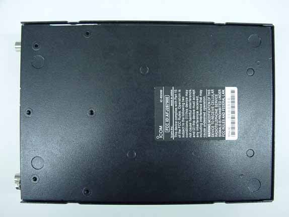
Click to zoom
Application Details
- Equipment Class
- CSR - Scanning Receiver
- Date of Grant
- Apr 24, 2006
- Application Purpose
- Original Equipment
- Date of Application
- Apr 24, 2006
- Equipment Note
- Communication Receiver
- Frequency Range
- 0.49500000 - 960.00000000
- Company
- ICOM Incorporated
- Country
- Japan
Documents & Files
Document Text
Text extracted from the exhibit documents filed with the FCC. Open a document above to read the original.
Users Manual
INSTRUCTION MANUAL iR2500 COMMUNICATION RECEIVER This device complies with Part 15 of the FCC rules. Operation is sub-ject to the following two conditions: (1) This device may not causeharmful interference, and (2) this device must accept any interferencereceived, including interference that may cause undesired operation. i FOREWORDThank you for purchasing this Icom product. The IC-R2500VHF / UHF FM RECEIVER is designed and built with Icom’s supe- rior technology and craftsmanship. With proper care, this prod-uct should provide you with years of trouble-free operation. We want to take a couple of moments of your time to thank you for making your IC-R2500 your radio of choice, and hopeyou agree with Icom’s philosophy of “technology first.” Manyhours of research and development went into the design ofyour IC-R2500. DD FEATURES ❍ W ide frequency coverage with all mode re- ceive ❍ Both Remote controller operation and PCcontrol application are available ❍ ANF and NR functions are available (Only when the optional DSP unit is installed.) ❍ IF shift function IMPORTANTREAD ALL INSTRUCTIONS carefully and completely before using the receiver. SAVE THIS INSTRUCTION MANUAL— This in- struction manual contains important operating instructions forthe IC-R2500. EXPLICIT DEFINITIONS WORD DEFINITION R W ARNING! CAUTION NOTE Personal injury, fire hazard or electric shockmay occur.Equipment damage may occur.Recommended for optimum use. No risk ofpersonal injury, fire or electric shock. Icom, Icom Inc. and the logo are registered trademarks of Icom Incorporated (Japan) in the United States, the United Kingdom, Ger-many, France, Spain, Russia and/or other countries. R W ARNING! NEVER connect the receiver via the OPC- 254L to an AC outlet. This may pose a fire hazard or result in an elec-tric shock. R W ARNING! NEVER operate the receiver while driving a vehicle. Safe driving requires your full attention— anything less mayresult in an accident. NEVER connect the receiver to a power source of more than 14 V DC. This will damage the receiver. NEVER connect the receiver to a power source using reverse po- larity. This will damage the receiver. NEVER cut the DC power cable between the DC plug and fuse holder. If an incorrect connection is made after cutting, the receivermay be damaged. NEVER expose the receiver to rain, snow or any liquids. The re- ceiver may be damaged. NEVER operate or touch the receiver with wet hands. This may result in an electric shock or damage the receiver. NEVER place the receiver where normal operation of the vehicle may be hindered or where it could cause bodily injury. NEVER let objects impede the operation of the cooling fan on the rear panel. A VOID using or placing the receiver in direct sunlight or in areas with temperatures below –10°C (+14°F) or above +60°C (+140°F). BE CAREFUL! The receiver will become hot when operating it continuously for long periods. A VOID setting the receiver in a place without adequate ventilation. Heat dissipation may be affected, and the receiver may be damaged. A VOID the use of chemical agents such as benzine or alcohol when cleaning, as they can damage the receiver’s surfaces. For U.S.A. onlyCAUTION: Changes or modifications to this device, not ex- pressly approved by Icom Inc., could void your authority tooperate this device under FCC regulations. ii PRECAUTION iii T ABLE OF CONTENTS FOREWORD ........................................................................................... iIMPORTANT ............................................................................................ iEXPLICIT DEFINITIONS ......................................................................... iPRECAUTIONS ...................................................................................... iiSUPPLIED ACCESSORIES .................................................................. iiiSPECIFICATIONS ................................................................................. iiiOPTIONS ............................................................................................... iiiT ABLE OF CONTENTS ......................................................................... iii 1 CONNECTION .............................................................................. 1–2■ Rear panel connection .................................................................... 1 ■ Antenna installation ........................................................................ 2 2P ANEL DESCRIPTION ................................................................. 3–7 ■ Front panel—controller .................................................................. 3 ■ Function display—controller ........................................................... 5 ■ Rear panel—main unit ................................................................... 7 3 SETTING A FREQUENCY .......................................................... 8–10■ T urning power ON/OFF ................................................................. 8 ■ Mode selection ............................................................................... 8 ■ T uning step selection ..................................................................... 9 ■ Setting a frequency ........................................................................ 9 ■ Receive mode selection ............................................................... 10 4 BASIC OPERATION ................................................................. 11–15■ Receiving ..................................................................................... 11 ■ Monitor function ............................................................................ 11 ■ Lock function ................................................................................ 11 ■ Attenuator function........................................................................ 12 ■ NB function .................................................................................. 12 ■ AGC function…
Text truncated - open the document above for the full version.
Cover Letter(s)
April 10, 2006 AmericanTCB, Inc. 6731 Whittier Avenue, Suite C110 McLean, VA 22101 Subject: Certification Testing in accordance with FCC CFR 47, Part 15, Subpart B - Scanning Receivers Operating in the Frequency Band 0.495 to 3299.9999 MHz (excluding cellular bands). Product: Communication Receiver Model Nos.: IC-R2500 & IC-PCR2500 FCC ID: AFJ287900 Dear Sir/Madam As appointed agent for ICOM Incorporated, we would like to submit the application for FCC certification of the above product. Please review all files uploaded to AmericanTCB electronic filing site. If you have any queries, please do not hesitate to contact us. Yours truly, Tri Minh Luu, P. Eng., V.P., Engineering UltraTech Group of Labs 31040/SIT C-1376 46390-2049 200093-0 2 00-034 SL2-IN-E-1119R 3000 Bristol Circle, Oakville, Ontario, Canada L6H 6G4 Tel.: (905) 829-1570 Fax.: (905) 829-8050 Website: www.ultratech-labs.com Email: [email protected]
Test Report
Communication Receiver Model Nos.: IC-R2500 & IC-PCR2500 FCC ID: AFJ287900 Applicant: ICOM Incorporated 1-1-32, Kamiminami, Hirano-ku Osaka, Japan, 547-0003 Tested in Accordance With Federal Communications Commission (FCC) 47 CFR, Part 15, Subpart B Scanning Receivers Operating in the Frequency Band 0.495 to 3299.9999 MHz (excluding cellular bands) UltraTech's File No.: ICOM-129FCC15RX This Test report is Issued under the Authority of Tri M. Luu, Professional Engineer, Vice President of Engineering UltraTech Group of Labs Date: April 10, 2006 Report Prepared by: Dharmajit Solanki Issued Date: April 10, 2006 Tested by: Wayne Wu, EMI/RFI Technician Test Dates: Mar.22 - Apr.03, 2006 The results in this Test Report apply only to the sample(s) tested, and the sample tested is randomly selected. This report must not be used by the client to claim product endorsement by NVLAP or any agency of the US Government. UltraTech 3000 Bristol Circle, Oakville, Ontario, Canada, L6H 6G4 Tel.: (905) 829-1570 Fax.: (905) 829-8050 Website: www.ultratech-labs.com , Email: [email protected], Email: [email protected] 2 31040/SIT C-1376 46390-2049 200093-0 SL2-IN-E-1119R 00-034 FCC Part 15, Subpart B, Part 15.121 Page 1 Communication Receiver, Models: IC-R2500 & IC-PCR2500 FCC ID: AFJ287900 ULTRATECH GROUP OF LABS File #: ICOM-129FCC15RX 3000 Bristol Circle, Oakville, Ontario, Canada L6H 6G4 April 10, 2006 Tel.: 905-829-1570, Fax. : 905-829-8050 All test results contained in this engineering test report are traceable to National Institute of Standards and Technology (NIST) TABLE OF CONTENTS EXHIBIT 1. SUBMITTAL CHECK LIST..................................................................................................................... 3 EXHIBIT 2. INTRODUCTION ...................................................................................................................................... 4 2.1. SCOPE...................................................................................................................................................................... 4 2.2. RELATED SUBMITTAL(S)/GRANT(S) ............................................................................................................... 4 2.3. NORMATIVE REFERENCES ................................................................................................................................ 4 EXHIBIT 3. PERFORMANCE ASSESSMENT ........................................................................................................... 5 3.1. CLIENT INFORMATION ....................................................................................................................................... 5 3.2. EQUIPMENT UNDER TEST (EUT) INFORMATION .........................................................................................5 3.3. EUT’S TECHNICAL SPECIFICATIONS .............................................................................................................. 6 3.4. LIST OF EUT’S PORTS.......................................................................................................................................... 6 3.5. ANCILLARY EQUIPMENT ................................................................................................................................... 6 3.6. DRAWING OF TEST SETUP ................................................................................................................................. 7 EXHIBIT 4. EUT OPERATING CONDITIONS AND CONFIGURATIONS DURING TESTS ............................ 2 4.1. CLIMATE TEST CONDITIONS ............................................................................................................................ 2 4.2. OPERATIONAL TEST CONDITIONS & ARRANGEMENT FOR TEST SIGNALS.......................................... 2 EXHIBIT 5. SUMMARY OF TEST RESULTS ............................................................................................................ 7 5.1. LOCATION OF TESTS........................................................................................................................................... 7 5.2. APPLICABILITY & SUMMARY OF EMC EMISSION TEST RESULTS .......................................................... 7 5.3. MODIFICATIONS REQUIRED FOR COMPLIANCE..........................................................................................7 EXHIBIT 6. MEASUREMENTS, EXAMINATIONS & TEST DATA FOR EMC EMISSIONS............................ 8 6.1. TEST PROCEDURES.............................................................................................................................................. 8 6.2. MEASUREMENT UNCERTAINTIES ................................................................................................................... 8 6.3. MEASUREMENT EQUIPMENT USED ................................................................................................................ 8 6.4. AC POWER LINE CONDUCTED EMISSIONS [§ 15.107(A)]............................................................................. 9 6.4.1. LIMITS.............................................................................................................................................................. 9 6.4.2. METHOD OF MEASUREMENTS.................................................................................................................... 9 6.4.3. TEST EQUIPMENT LIST ................................................................................................................................. 9 6.4.4. PHOTOS OF TEST SETUP.............................................................................................................................. 9 6.4.5. TEST DATA .................................................................................................................................................... 10 6.5. RECEIVER ANTENNA POWER SPURIOUS/HARMONIC CONDUCTED EMISSIONS [§15.111(A)] ........ 13 6.5.1. LI…
Text truncated - open the document above for the full version.
Test Setup Photos
ANNEX 1 - TEST SETUP PHOTOGRAPHS Icom Inc. Communication Receiver, Model: IC-R2500 FCC ID: AFJ287900, IC: 202D-287900 Photo #1: AC Powerline Conducted Emissions ANNEX 1 - TEST SETUP PHOTOGRAPHS Icom Inc. Communication Receiver, Model: IC-R2500 FCC ID: AFJ287900, IC: 202D-287900 Photo #2: AC Powerline Conducted Emissions ANNEX 1 - TEST SETUP PHOTOGRAPHS Icom Inc. Communication Receiver, Model: IC-R2500 FCC ID: AFJ287900, IC: 202D-287900 Photo #3: Receiver Radiated Emissions at 3 meters OFTS ANNEX 1 - TEST SETUP PHOTOGRAPHS Icom Inc. Communication Receiver, Model: IC-R2500 FCC ID: AFJ287900, IC: 202D-287900 Photo # 4: Radiated Emissions at 3 meters OFTS ANNEX 1 - TEST SETUP PHOTOGRAPHS Icom Inc. Communication Receiver, Model: IC-R2500 FCC ID: AFJ287900, IC: 202D-287900 Photo # 5: Radiated Emissions at 3 meters OFTS
Contact Information
Applicant
Tatsuo Yano(General Manager of QA Department)
Technical Contact
Test Firm
UltraTech Engineering Labs Inc.Tri Luu
Technical Specifications
| # | Rule Parts | Frequency Range | Power Output |
|---|---|---|---|
| 1 | 15B | 0.495 MHz - 960 MHz | - |
Other Applications from ICOM Incorporated

AFJ453700
Jul 23, 2026Mobile Transceiver
Equipment Class
DTS - Digital Transmission System
AFJ452000
Jun 02, 2026VHF DIGITAL TRANSCEIVER
Equipment Class
TNF - Licensed Non-Broadcast Transmitter Held to Face
AFJ452100
May 12, 2026UHF DIGITAL TRANSCEIVER
Equipment Class
TNF - Licensed Non-Broadcast Transmitter Held to Face
AFJ444500
Sep 12, 2024Scanning Receiver
Equipment Class
CSR - Scanning Receiver
AFJ410900
Jul 09, 2024Linear Amplifier
Equipment Class
AMP - Amplifier