AFJ296400Scanning Receiver
ICOM Incorporated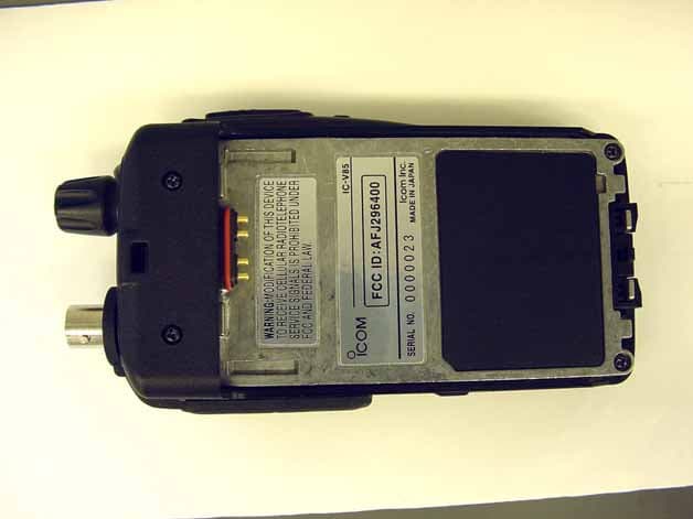
Click to zoom
Application Details
- Equipment Class
- CSR - Scanning Receiver
- Date of Grant
- Jan 07, 2007
- Application Purpose
- Original Equipment
- Date of Application
- Jan 07, 2007
- Equipment Note
- Scanning Receiver
- Frequency Range
- 136.00000000 - 174.00000000
- Company
- ICOM Incorporated
- Country
- Japan
Documents & Files
Document Text
Text extracted from the exhibit documents filed with the FCC. Open a document above to read the original.
Users Manual
INSTRUCTION MANUAL This device complies with Part 15 of the FCC Rules. Operation issubject to the following two conditions: (1) this device may not causeharmful interference, and (2) this device must accept any interferencereceived, including interference that may cause undesired operation. iV85 FM TRANSCEIVER iV85EiV85-T i FOREWORDThank you for purchasing this Icom transceiver. The IC-V85FM TRANSCEIVER is designed and built with Icom’s superior technology and craftsmanship. With proper care, this trans-ceiver should provide you with years of trouble-free operation. We want to take a couple of moments of your time to thank you for making the IC-V85 your radio of choice, and hope youagree with Icom’s philosophy of “technology fi rst.” Many hours of research and development went into the design of your IC-V85. DD FEATURES ❍ 7 W*— high transmit output power *7 W : IC-V85 except [THA] version, 5.5 W : IC-V85 [THA] version ❍ CTCSS and DTCS encoder/decoder stan-dard ❍ Optional DTMF decoder IMPORTANTREAD ALL INSTRUCTIONS carefully and completely before using the transceiver. SAVE THIS INSTRUCTION MANUAL— This in- struction manual contains important operating instructions forthe IC-V85. EXPLICIT DEFINITIONS WORD DEFINITION R W ARNING! CAUTION NOTE Personal injury, fi re hazard or electric shock may occur.Equipment damage may occur.Recommended for optimum use. No risk ofpersonal injury, fi re or electric shock. Icom, Icom Inc. and the logo are registered trademarks of Icom Incorporated (Japan) in the United States, the United Kingdom, Ger-many, France, Spain, Russia and/or other countries. ii R W ARNING RF EXPOSURE! This device emits Radio Frequency (RF) energy. Extreme caution should be ob-served when operating this device. If you have any questionsregarding RF exposure and safety standards please refer tothe Federal Communications Commission Office of Engi-neering and Technology’s report on Evaluating Compliancewith FCC Guidelines for Human Radio frequency Electro-magnetic Fields (OET Bulletin 65) R W ARNING! NEVER hold the transceiver so that the antenna is very close to, or touching exposed parts of thebody, especially the face or eyes, while transmitting. Thetransceiver will perform best if the microphone is 5 to 10 cm(2 to 4 inches) away from the lips and the transceiver is verti-cal. R W ARNING! NEVER operate the transceiver with a headset or other audio accessories at high volume levels.Hearing experts advise against continuous high volume op-eration. If you experience a ringing in your ears, reduce thevolume or discontinue use. R W ARNING! NEVER operate the transceiver while driving a vehicle. Safe driving requires your full attention—anything less may result in an accident. R W ARNING! NEVER connect the transceiver to an AC outlet. This may pose a fi re hazard or result in an electric shock. NEVER connect a power supply of more than 16 V DC through the optional CP-19R CIGARETTE LIGHTER CABLE to the [DC 11V] jack to prevent damaging the transceiver. NEVER connect the transceiver to a power source using reverse polarity. This will ruin the transceiver. NEVER cut the DC power cable between the DC plug and fuse holder. If an incorrect connection is made after cutting,the transceiver may be damaged. NEVER expose the transceiver to rain, snow or any liquids. The transceiver may be damaged. NEVER operate or touch the transceiver with wet hands. This may result in an electric shock or ruin the transceiver. NEVER attempt to charge alkaline or dry cell batteries. Be aware that external DC power connections will charge batter-ies inside the battery case. This will damage not only the bat-tery case but also the transceiver. DO NOT push the PTT when not actually desiring to trans- mit. PRECAUTIONS iii SUPPLIED ACCESSORIESq Antenna* . . . . . . . . . . . . . . . . . . . . . . . . . . . . . . . . . . . . . 1 w Hand strap* . . . . . . . . . . . . . . . . . . . . . . . . . . . . . . . . . . . 1 e 2251 OPT sheet*. . . . . . . . . . . . . . . . . . . . . . . . . . . . . . . 1 r Battery pack*/Battery case* . . . . . . . . . . . . . . . . . . . . . . 1 t Belt clip* (with screws) . . . . . . . . . . . . . . . . . . . . . . . . . . 1 y AC Adapter*. . . . . . . . . . . . . . . . . . . . . . . . . . . . . . . . . . . 1 *Not supplied with some versions. y qw t e r DO NOT operate the transceiver near unshielded electrical blasting caps or in an explosive atmosphere. BE CAREFUL! The transceiver will become hot when operating it continuously for long periods. A VOID using or placing the transceiver in direct sunlight or in areas with temperatures below –10°C (+14 ̊ F) or above +60°C (+140 ̊ F). Place the unit in a secure place to avoid inadvertent use bychildren. A VOID the use of chemical agents such as benzine or al- cohol when cleaning, as they can damage the transceiver’ssurfaces.Even when the transceiver power is OFF, a slight current stillfl ows in the circuits. Remove the battery pack or case from the transceiver when not using it for a long time. Otherwise,the battery pack (Li-Ion: BP-227) or installed batteries will be-come exhausted.For USA only:Caution: Changes or modi fi cations to this transceiver, not ex- pressly approved by Icom Inc., could void your authority tooperate this transceiver under FCC regulations. PRECAUTIONS—continued iv • BP-226 BATTERY CASE Battery case for 5 × AA (LR6) size alkaline batteries. • BP-227 LI - ION BATTERY PACK 7.2 V/1700 mAh Lithium-Ion battery pack. • BC-119N DESKTOP CHARGER + AD-100 CHARGER ADAPTER For rapid charging of battery packs. An AC adapter is sup-plied with the charger. Charging time: approx. 2–2.5 hrs. • BC-121N MULTI - CHARGER + AD-100 CHARGER ADAPTER (6 pcs.) For rapid charging of up to 6 battery packs (six AD-100’s arerequired) simultaneously. An AC adapter may be supplieddepending on version. Charging time: approx. 2–2.5 hrs. • CP-19R CIGARETTE LIGHTER CABLE WITH NOISE FILTER Used for operation and charging a battery pack connectedto transceiver via a DC …
Text truncated - open the document above for the full version.
Test Report
SCANNING RECEIVER Model No.: IC-V85 FCC ID: AFJ296400 Applicant: ICOM Incorporated 1-1-32, Kamiminami Hirano-ku, Osaka Japan, 547-003 Tested in Accordance With Federal Communications Commission (FCC) 47 CFR, Part 15, Subpart B Scanning Receivers operating in the Frequency Band 136-174 MHz UltraTech's File No.: ICOM-140-FCC15R This Test report is Issued under the Authority of Tri M. Luu, Professional Engineer, Vice President of Engineering UltraTech Group of Labs Date: January 4, 2007 Report Prepared by: JaeWook Choi Issued Date: January 4, 2007 Tested by: Wayne Wu, EMI/RFI Technician Test Dates: December 5, 6 & 11, 2006 The results in this Test Report apply only to the sample(s) tested, and the sample tested is randomly selected. This report must not be used by the client to claim product endorsement by NVLAP or any agency of the US Government. UltraTech 3000 Bristol Circle, Oakville, Ontario, Canada, L6H 6G4 Tel.: (905) 829-1570 Fax.: (905) 829-8050 Website: www.ultratech-labs.com , Email: [email protected], Email: [email protected] 0685 31040/SIT C-1376 46390-2049 200093-0 SL2-IN-E-1119R FCC PART 15, SUBPART B, SCANNING RECEIVERS Page 2 SCANNING RECEIVER, Model IC-V85 FCC ID: AFJ296400 ULTRATECH GROUP OF LABS File #: ICOM-140-FCC15R 3000 Bristol Circle, Oakville, Ontario, Canada L6H 6G4 January 4, 2007 Tel.: 905-829-1570, Fax. : 905-829-8050 All test results contained in this engineering test report are traceable to National Institute of Standards and Technology (NIST) TABLE OF CONTENTS EXHIBIT 1. INTRODUCTION ...................................................................................................................................... 3 1.1. SCOPE...................................................................................................................................................................... 3 1.2. RELATED SUBMITTAL(S)/GRANT(S)................................................................................................................ 3 1.3. NORMATIVE REFERENCES ................................................................................................................................ 3 EXHIBIT 2. PERFORMANCE ASSESSMENT ........................................................................................................... 4 2.1. CLIENT INFORMATION ....................................................................................................................................... 4 2.2. EQUIPMENT UNDER TEST (EUT) INFORMATION .......................................................................................... 4 2.3. EUT’S TECHNICAL SPECIFICATIONS ............................................................................................................... 5 2.4. ANCILLARY EQUIPMENT ................................................................................................................................... 5 2.5. DRAWING OF TEST SETUP.................................................................................................................................. 6 EXHIBIT 3. EUT OPERATING CONDITIONS AND CONFIGURATIONS DURING TESTS ............................ 7 3.1. CLIMATE TEST CONDITIONS ............................................................................................................................. 7 3.2. OPERATIONAL TEST CONDITIONS & ARRANGEMENT FOR TEST SIGNALS ........................................... 7 EXHIBIT 4. SUMMARY OF TEST RESULTS ............................................................................................................ 8 4.1. LOCATION OF TESTS ........................................................................................................................................... 8 4.2. APPLICABILITY & SUMMARY OF EMC EMISSION TEST RESULTS ............................................................ 8 4.3. MODIFICATIONS REQUIRED FOR COMPLIANCE .......................................................................................... 8 EXHIBIT 5. MEASUREMENTS, EXAMINATIONS & TEST DATA FOR EMC EMISSIONS............................ 9 5.1. TEST PROCEDURES.............................................................................................................................................. 9 5.2. MEASUREMENT UNCERTAINTIES ...................................................................................................................9 5.3. MEASUREMENT EQUIPMENT USED................................................................................................................. 9 5.4. ESSENTIAL/PRIMARY FUNCTIONS AS DECLARED BY THE MANUFACTURER ...................................... 9 5.5. AC POWERLINE CONDUCTED EMISSIONS [47 CFR 15.107 (A)] .................................................................. 10 5.6. RECEIVER ANTENNA POWER SPURIOUS/HARMONIC CONDUCTED EMISSIONS [47 CFR 15.111(A)] 14 5.7. RECEIVER SPURIOUS/HARMONIC RADIATED EMISSIONS [47 CFR 15.109(A)] ...................................... 18 5.8. RADIATED EMISSIONS FROM CLASS B UNINTENTIONAL RADIATION (DIGITAL DEVICE) [47 CFR 15.109 (B)] .......................................................................................................................................................................... 21 5.9. REQUIREMENTS FOR SCANNING RECEIVERS [47 CFR 15.121] ................................................................. 22 EXHIBIT 6. MEASUREMENT UNCERTAINTY...................................................................................................... 25 6.1. LINE CONDUCTED EMISSION MEASUREMENT UNCERTAINTY.............................................................. 25 6.2. RADIATED EMISSION MEASUREMENT UNCERTAINTY ............................................................................ 26 EXHIBIT 7. MEASUREMENT METHODS ............................................................................................................... 27 7.1. GENERAL TEST CONDITIONS ...............................…
Text truncated - open the document above for the full version.
Test Setup Photos
Test Setup Photographs – ICOM Scanning Receiver (M/N: IC-V85)
Contact Information
Applicant
Tatsuo Yano(General Manager of QA Department)
Technical Contact
Test Firm
UltraTech Engineering Labs Inc.Tri Luu
Technical Specifications
| # | Rule Parts | Frequency Range | Power Output |
|---|---|---|---|
| 1 | 15B | 136 MHz - 174 MHz | - |
Other Applications from ICOM Incorporated

AFJ453700
Jul 23, 2026Mobile Transceiver
Equipment Class
DTS - Digital Transmission System
AFJ452000
Jun 02, 2026VHF DIGITAL TRANSCEIVER
Equipment Class
TNF - Licensed Non-Broadcast Transmitter Held to Face
AFJ452100
May 12, 2026UHF DIGITAL TRANSCEIVER
Equipment Class
TNF - Licensed Non-Broadcast Transmitter Held to Face
AFJ444500
Sep 12, 2024Scanning Receiver
Equipment Class
CSR - Scanning Receiver
AFJ410900
Jul 09, 2024Linear Amplifier
Equipment Class
AMP - Amplifier