AFJ297410VHF Air Band Transceiver
ICOM Incorporated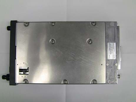
Click to zoom
Application Details
- Equipment Class
- TNB - Licensed Non-Broadcast Station Transmitter
- Date of Grant
- Mar 10, 2015
- Application Purpose
- Original Equipment
- Date of Application
- Mar 10, 2015
- Equipment Note
- VHF Air Band Transceiver
- Frequency Range
- 118.00000000 - 136.99170000
- Company
- ICOM Incorporated
- Country
- Japan
Documents & Files
Document Text
Text extracted from the exhibit documents filed with the FCC. Open a document above to read the original.
Users Manual
VHF AIR BAND TRANSCEIVERS INSTRUCTION MANUAL This device complies with Par t 15 of the FCC Rules. Operation is subject to the condition that this device does not cause harmful interference. iA220E iA220 i IMPORTANT READ ALL INSTRUCTIONS carefully and completely before using the transceiver. SAVE THIS INSTRUCTION MANUAL — This in- struction manual contains important operating instructions for the IC-A220 and IC-A220E. The explicit definitions below apply to this instruction man- ual. WORDDEFINITION RWARNING! Personal injury, fire hazard or electric shock may occur. CAUTION Equipment damage may occur. NOTE If disregarded, inconvenience only. No risk of personal injury, fire or electric shock. Icom, Icom Inc. and Icom logo are registered trademarks of Icom Incorporated (Japan) in Japan, the United States, the United Kingdom, Germany, France, Spain, Russia, Australia, New Zealand, and/or other countries. FCC INFORMATION • FOR CLASS A UNINTENTIONAL RADIATORS: This equipment has been tested and found to comply with the limits for a Class A digital device, pursuant to part 15 of the FCC Rules. These limits are designed to provide reasonable protection against harmful interference when the equipment is operated in a commercial environment. This equipment generates, uses and can radiate radio frequency energy and, if not installed and used in accordance with the instruction manual, may cause harmful interference to radio communi- cations. Operation of this equipment in a residential area is likely to cause harmful interference in which case the user will be required to correct the interference at his own expense. • POUR LES RAYONNEMENTS NON INTENTIONNELS DE CLASSE A: Cet équipement a été testé et reconnu conforme aux limites fixées pour un appareil numérique de classe A, conformément au point 15 de la réglementation FCC. Ces limites sont définies de façon à fournir une protection raisonnable contre le brouillage préjudiciable lorsque cet appareil est utilisé dans un environnement commercial. Cet équipement génère, utilise et peut émettre un rayonnement de fréquence radio. S'il n'a pas été installé conformément aux instruc- tions, il peut par ailleurs créer des interférences perturbant les com- munications radio. L'utilisation de cet appareil dans une zone résidentielle peut provo- quer un brouillage préjudiciable, auquel cas l'utilisateur sera tenu de corriger la situation à ses frais. EXPLICIT DEFINITIONS ii DO NOT push the PTT when not actually intending to transmit. DO NOT use or place the transceiver in direct sunlight or in areas with temperatures below –20°C (–4°F) or above +55°C (+131°F). DO NOT place the transceiver in excessively dusty envi- ronments. DO NOT use harsh solvents such as benzine or alcohol to clean the transceiver, as they will damage the transceiver’s surfaces. If the transceiver becomes dusty or dirty, wipe it clean with a soft, dry cloth. BE CAREFUL! The transceiver will become hot when operating continuously for long periods. PRECAUTIONS R WARNING! NEVER operate the transceiver with an earphone or other audio accessories at high volume lev- els. Continuous high volume operation may cause a ringing in your ears. If you experience ringing, reduce the volume level or discontinue use. R WARNING! NEVER connect the transceiver to an AC outlet or to a power source of more than 28 V DC. Such a connection will damage the transceiver. CAUTION: NEVER connect the transceiver to a power source that is DC fused at more than 10 A. Accidental reverse connection will be protected by this fuse, higher fuse values will not give any protection against such accidents and the transceiver will be damaged. DO NOT operate the transceiver near unshielded electric blasting caps or in an explosive atmosphere. DO NOT connect the transceiver to a power source using reverse polarity. This connection will not only blow fuses but also may damage the transceiver. DO NOT place unit in a non-secure place to avoid inadver- tent use by children. CAUTION: Changes or modifications to this transceiver, not expressly approved by Icom Inc., could void your authority to operate this transceiver under FCC regulations. iii NE PAS d’utiliser ou d’exposer l’émetteur-récepteur en plein soleil ou à une tem pérature ambiante inférieure à –20°C ou supérieure à +55°C. NE PAS placer l'émetteur-récepteur dans des endroits ex- cessivement poussiéreux. NE PAS nettoyer l'appareil avec des solvants agressifs tels que benzène ou alcool, susceptibles d'endommager les sur- faces exposées du boîtier. En cas de dépôt de poussière ou de salissures sur l'émetteur-récepteur, il faut l'essuyer avec chiffon doux et sec. ATTENTION! Le transceiver devient chaud lors d'utilisations continues de longue durée. L’émetteur-récepteur chauffe en cas d’utilisation continue sur une longue durée. L'antenne doit être placée à au moins un mètre de la position de chacune des personnes à bord de l'aéronef. PRÉCAUTIONS R NE JAMAIS utiliser l’émetteur-récepteur avec un casque ou d’autres accessoires audio ayant un volume trop élevé. Un volume continu trop fort peut entraîner un bour- donnement dans vos oreilles. Si vous entendez une sonnerie baissez le niveau sonore ou interrompez l'utilisation. R NE JAMAIS relier l'émetteurrécepteur à une prise d'alimentation de plus de 28 V. Un tel branchement endom- magerait votre émetteur-récepteur. NE JAMAIS brancher l’émetteur-récepteur à une ali- mentation continue dont le fusible de protection excède 10 A. Ce fusible protège contre l’inversion accidentelle des branchements. NE PAS utiliser l'émetteur-récepteur près d'amorces élec- triques non blindées ou en atmosphère explosive. NE JAMAIS brancher le transceiver à une source d'alimentation employant la polarité inversée. NE PAS appuyer sur la touche PTT lorsqu’on ne souhaite pas émettre. iv SAFETY TRAINING INFORMATION Your Icom radio generates RF electromag- netic energy during transmit mode. This radio is designed for and classified as “Oc- cupational Use Only,” …
Text truncated - open the document above for the full version.
Attestation Statements
UltraTech Group of Labs FCC TCB & IC CB Ultratech’s Accreditations: 0685 FCC 91038 1309 46390-2049 NvLap Lab Code 200093-0 SL2-IN-E-1119R Korea KCC-RRL CA2049 3000 Bristol Circle, Oakville, Ontario, Canada L6H 6G4 Tel.: (905) 829-1570 Fax.: (905) 829-8050 Website: www.ultratech-labs.com Email: [email protected] March 02, 2015 To, Ms. Annette Allender ATO Spectrum Planning and International Federal Aviation Administration Subject: Information for FAA Review for FCC Certification Application for following VHF Radio under FCC 47 CFR, Parts 2 and 87 (Subpart D) - Non-broadcast Aviation Radio Services Operating in the Frequency Band 118-136.9917MHz Applicant: ICOM Incorporated Product: VHF Air Band Transceiver Models: IC-A220 FCC ID: AFJ297410 Dear Ms. Allander, As appointed agent for ICOM Incorporated, we herewith submit the necessary information required for FAA review & approval. This may enable us (FCC TCB, UltraTech Engineering Labs Inc.) to review & grant FCC application for Certification of the above product. Please find them in following pages and let us know if you may have any question or require further information. Thanking you. Sincerely, Dharmajit Solanki Dharmajit Solanki Authorized Agent Email:[email protected] VHF Air Band Transceiver Model Nos.: IC-A220 FCC ID: AFJ297410 Applicant: ICOM Incorporated 1-1-32, Kamiminami, Hirano-ku Osaka, Japan, 547-0003 Tested as Required for FAA Review For FCC Certification under Federal Communications Commission (FCC) 47 CFR, Parts 2 and 87 (Subpart D) – Aviation Services UltraTech's File No.: 15ICOM404_FAA This Test report is Issued under the Authority of Tri M. Luu, BASc Vice President of Engineering UltraTech Group of Labs Date: March 02, 2015 Report Prepared by: Dharmajit Solanki Issued Date: March 02, 2015 Tested by: Wei Wu Test Dates: March 02, 2015 The results in this Test Report apply only to the sample(s) tested, and the sample tested is randomly selected. This report must not be used by the client to claim product endorsement by NVLAP or any agency of the US Government. UltraTech 3000 Bristol Circle, Oakville, Ontario, Canada, L6H 6G4 Tel.: (905) 829-1570 Fax.: (905) 829-8050 Website: www.ultratech-labs.com , Email: [email protected], Email: [email protected] Korea KCC-RRA 91038 1309 46390-2049 NVLAP LAB CODE 200093-0 SL2-IN-E- 1119R CA2049 TL363_B TPTDP DA1300 FCC Parts 2 and 87, Subpart D, Non-Broadcast Aviation Radio Services Page 1 VHF Air Band Transceiver, Model: IC-A220 FCC ID: AFJ297410 ULTRATECH GROUP OF LABS File #: 15ICOM404_FAA 3000 Bristol Circle, Oakville, Ontario, Canada L6H 6G4 March 02, 2015 Tel. #: 905-829-1570, Fax. #: 905-829-8050, Email: [email protected] , Website: http://www.ultratech-labs.com All test results contained in this engineering test report are traceable to National Institute of Standards and Technology (NIST) FAA Requested Information:- 1.) FCC identification number FCC ID: AFJ297410 2.) Manufacture and Model number Manufacture: Icom Inc, 1-1-32, Kamiminami, Hirano-ku, Osaka, Japan, 547-0003 Model number: IC-A220 3.) Rated transmitter output power Rated Output Power: 8 W 4.) Frequency Range (capable of tuning). Frequency Tuning Range: 118.000 to 136.9917 MHz Receive Only: 161 to 164 MHz 5.) Method of tuning Microprocessor controlled phased lock loop (PLL) arrangement 6.) Channeling capability The Transceiver will operate from 118 MHz -136.975 MHz for 25 kHz Ch Spacing & 118 MHz -136.9917 MHz for 8.33 kHz Ch Spacing 7.) Frequency stability (transmitter). +/- 5.0 ppm 8.) Emission bandwidth(s) 6.00 kHz 9.) Emission type(s) Amplitude modulation (AM) A3E 25 kHz: 6K00A3E 8.33 kHz: 5K60A3E FCC Parts 2 and 87, Subpart D, Non-Broadcast Aviation Radio Services Page 2 VHF Air Band Transceiver, Model: IC-A220 FCC ID: AFJ297410 ULTRATECH GROUP OF LABS File #: 15ICOM404_FAA 3000 Bristol Circle, Oakville, Ontario, Canada L6H 6G4 March 02, 2015 Tel. #: 905-829-1570, Fax. #: 905-829-8050, Email: [email protected] , Website: http://www.ultratech-labs.com All test results contained in this engineering test report are traceable to National Institute of Standards and Technology (NIST) 10.) Spectral emission plots: (1) One centered on frequency middle of the range and measured across that range. (2) Another of frequencies measured out to its corresponding 12th or 13th harmonic. Test Frequencies & Plots #: Refer to plots for details 1. 118.025 MHz – Plots # 1 & 2 2. 127.500 MHz – Plots # 3 & 4 3. 136.975 MHz – Plots # 5 & 6 11.) Harmonics levels for the (ground) transceiver frequencies listed in Fig.1. 11.1 Transmit Frequency Harmonics (12 & 13) Transmit Frequency (MHz) Harmonic Harmonic Frequency (MHz) Plot # & Level (dBm)* 130.625 12 1567.500 # 7 & - 68.1 131.275 12 1575.300 # 8 & - 67.4 134.150 12 1609.800 # 9 & - 68.4 120.925 13 1572.025 # 10 & - 68.0 121.175 13 1575.275 # 11 & - 68.7 123.825 13 1609.725 # 12 & - 68.0 * See the plots for details of measurements 12.) Receiver RF characteristics Sensitivity: 6 dB S/N 2 μV Selectivity: 6 dB ± 3 KHz (Ch Space 25 kHz) 6 dB ± 2.778 KHz (Ch Space 8.33 kHz) 60 dB ± 22 KHz (Ch Space 25 kHz) 60 dB ± 7.37 KHz (Ch Space 8.33 kHz) Spurious Responses: 74 dB μ Audio Output Power: 5 W (4 ohms) / 60 mW (500 ohms) Receive System: Double Conversion Superheterodyne Intermediate Frequency: 1st 38.85 MHz 2nd 450 KHz 13.) Avionics Does the transceiver meet the standard for desensitization? (They are specified in Section 2.2.11 of RTCA DO-186 Minimum Operational Performance Standards for Airborne Radio Communications Equipment Operating within the radio frequency Range 117.975-137.000 MHz), which provides immunity from FM broadcast. No, this is non TSO radio, and does not meet Section 2.2.11 of RTCA DO-186 Minimum Operational Performance Standards FCC Parts 2 and 87, Subpart D, Non-Broadcast Aviation Radio Services Page 3 VHF Air Band Transceiver, Model: IC-A220 FCC ID: AFJ297410 ULTRATECH GROUP OF LABS File #: 15ICOM404_FAA 3000 Bristol Circle, Oakvi…
Text truncated - open the document above for the full version.
Cover Letter(s)
March 03, 2015 Ultratech Engineering Labs, Inc. 3000 Bristol Circle Oakville, Ontario L6H 6G4 Subject: Certification Application under FCC 47 CFR, Parts 2 and 87 (Subpart D) - Non-broadcast Aviation Radio Services Operating in the Frequency Band 118-136.9917 MHz. Applicant: ICOM Incorporated Product: VHF Air Band Transceiver Models: IC-A220 FCC ID: AFJ297410 Dear Sir/Madam: As appointed agent for ICOM Incorporated, we submit this application for FCC certification the above product. Please review all files uploaded to your electronic filing site. If you have any queries, please do not hesitate to contact us. Yours truly, Dharmajit Solanki Dharmajit Solanki Authorized Agent UltraTech Group of Labs FCC TCB & IC CB Ultratech’s Accreditations: 0685 91038 1309 46390-2049 NVLAP LAB CODE 200093-0 SL2-IN-E-1119R Korea KCC-RRA CA2049 TL363_B TPTDP DA1300 3000 Bristol Circle, Oakville, Ontario, Canada L6H 6G4 Tel.: (905) 829-1570 Fax.: (905) 829-8050 Website: www.ultratech-labs.com Email: [email protected]
External Photos
FRONT REAR FRONT REAR TOP BOTTOM TOP BOTTOM LEFT RIGHT LEFT RIGHT
ID Label/Location Info
Part15 Label ID Label FCC ID : AFJ297410 IC : 202D - 297410 SERIAL NO. MADE IN JAPAN Model : IC - A220 0000000
Internal Photos
MAIN-B(TOP) MAIN-B (BOTTOM) D-CONNECT(TOP) D-CONNECT(BOTTOM) MAIN-B(TOP) MAIN-B (BOTTOM) PA-B(TOP) PA-B(BOTTOM) PA-B(TOP) PA-B(BOTTOM) FRONT-B(TOP) FRONT-B(BOTTOM) FRONT-B(TOP) FRONT-B(BOTTOM) VR-B(TOP) VR(BOTTOM) VR-B(TOP) VR(BOTTOM) D-CONNECT(TOP) D-CONNECT(BOTTOM)
RF Exposure Info
iv SAFETY TRAINING INFORMATION Your Icom radio generates RF electromag- netic energy during transmit mode. This radio is designed for and classified as “Oc- cupational Use Only,” meaning it must be used only during the course of employment by individuals aware of the hazards, and the ways to minimize such hazards. This radio is NOT intended for use by the “General Popu- lation” in an uncontrolled environment. • For compliance with FCC and Industry Canada RF Expo- sure Requirements, the transmitter antenna installation shall comply with the following two conditions: 1. The transmitter antenna gain shall not exceed 0 dBi. 2. The antenna is required to be located outside of a ve- hicle and kept at a distance of 40 centimeters or more between the transmitting antenna of this device and any persons during operation. For a small vehicle, the an- tenna as worst case, the antenna shall be located on the roof top at any place on the centre line along the vehicle in order to achieve 40 centimeters separation distance. In order to ensure this distance is met, the installation of the antenna must be mounted at least 40 centimeters away from the nearest edge of the vehicle in order to protect against exposure to bystanders. To ensure that your exposure to RF elec- tromagnetic energy is within the FCC al- lowable limits for occupational use, always adhere to the following guidelines: • DO NOT operate the radio without a proper antenna at- tached, as this may damage the radio and may also cause you to exceed FCC RF exposure limits. A proper antenna is the antenna supplied with this radio by the manufacturer or an antenna specifically authorized by the manufacturer for use with this radio. • DO NOT transmit for more than 50% of total radio use time (“50% duty cycle”). Transmitting more than 50% of the time can cause FCC RF exposure compliance requirements to be exceeded. The radio is transmitting when the “TX” indica- tor appears. You can cause the radio to transmit by pressing the PTT switch. Electromagnetic Interference/Compatibility During transmissions, your Icom radio generates RF energy that can possibly cause interference with other devices or systems. To avoid such interference, turn off the radio in ar- eas where signs are posted to do so. DO NOT operate the transmitter in areas that are sensitive to electromagnetic ra- diation such as hospitals, aircraft, and blasting sites. v INFORMATION EN MATIÈRE DE SÉCURITÉ Votre radio Icom produit une énergie électro- magnétique de radiofréquences (RF), en mode de transmission. Cette radio est conçue pour un «usage professionnel seulement» et classée comme tel, ce qui signifie qu'elle doit être utili- sée uniquement dans le cadre d'un travail par des personnes conscientes des dangers et des mesures visant à minimiser ces dangers. Elle N'EST PAS conçue pour une «utilisation grand public», dans un environnement non contrôlé. • Afin de satisfaire aux exigences de la FCC et d'Industrie Canada en matière d'exposition aux RF, il est nécessaire que l'antenne soit installée confor- mément aux deux conditions suivantes: 1. Le gain de l'antenne du radio émetteur ne doit pas dépasser 0 dBi. 2. Il faut que l'antenne émettrice de cet appareil soit placée à l'extérieur d'un véhicule et tenue éloignée d'au moins 40 cen- timètres de toute personne pendant le fonctionnement. Dans le pire des cas, pour un petit véhicule, l'antenne doit être placée sur le toit, n'importe où dans l'axe central du véhicule, afin de respecter une distance de 40 cm du bord le plus rapproché du véhicule et ainsi éviter que les personnes présentes soient exposées. Afin de vous assurer que votre exposition à une énergie électromagnétique de RF se situe dans les limites permises par la FCC pour une utilisation grand public, veuillez en tout temps respecter les directives suivantes: • NE PAS faire fonctionner la radio sans qu'une antenne appropriée y soit fixée, car ceci risque d'endommager la radio et causer une exposition supérieure aux limites établies par la FCC. L'antenne ap- propriée est celle qui est fournie avec cette radio par le fabricant ou une antenne spécialement autorisée par le fabricant pour être utilisée avec cette radio. • NE PAS émettre pendant plus de 50% du temps total d'utilisation de l'appareil («50% du facteur d'utilisation»). Émettre pendant plus de 50% du temps total d'utilisation peut causer une exposition aux RF supérieure aux limites établies par la FCC. La radio est en train d’émettre lorsque le témoin du mode de transmission s'affiche sur l'écran ACL. La radio émettra si vous appuyez sur le bouton du microphone. Interférence électromagnétique et compatibilité En mode de transmission, votre radio Icom produit de l'énergie de RF qui peut provoquer des interférences avec d'autres appareils ou systèmes. Pour éviter de telles interférences, mettez la radio hors tension dans les secteurs où une signalisation l’exige. NE PAS faire fonctionner l'émetteur dans des secteurs sensibles au rayonnement électromagnétique tels que les hôpitaux, les aéronefs et les sites de dynamitage. AVERTISSEMENT MISE EN GARDE FCC Parts 2 and 87, Subpart D, Non-Broadcast Aviation Radio Services Page 45 VHF Air Band Transceiver, Models: IC-A220 FCC ID: AFJ297410 ULTRATECH GROUP OF LABS File #: 15ICOM401_FCC87 3000 Bristol Circle, Oakville, Ontario, Canada L6H 6G4 March 03, 2015 Tel. #: 905-829-1570, Fax. #: 905-829-8050, Email: [email protected] , Website: http://www.ultratech-labs.com All test results contained in this engineering test report are traceable to National Institute of Standards and Technology (NIST) 5.12. EXPOSURE OF HUMANS TO RF FIELD [[§§ 1.1310 & 2.1091] The criteria listed in the following table shall be used to evaluate the environmental impact of human exposure to radio-frequency (RF) radiation. FCC 47 CFR § 1.1310: 5.12.1. Method of Measurements See RSS-102 & FCC 47 CFR §§ 1.1310, 2.1091 In order to demonstrate compliance with MPE requirements, the following information is t…
Text truncated - open the document above for the full version.
Test Report
VHF Air Band Transceiver Model Nos.: IC-A220 FCC ID: AFJ297410 Applicant: ICOM Incorporated 1-1-32, Kamiminami, Hirano-ku Osaka, Japan, 547-0003 Tested in Accordance with Federal Communications Commission (FCC) 47 CFR, Parts 2 and 87 (Subpart D) – Aviation Services UltraTech's File No.: 15ICOM401_FCC87 This Test report is Issued under the Authority of Tri M. Luu, BASc Vice President of Engineering UltraTech Group of Labs Date: March 03, 2015 Report Prepared by: Dharmajit Solanki Issued Date: March 03, 2015 Tested by: Wei Wu Test Dates: Jan 28 to Feb 05, 2015 The results in this Test Report apply only to the sample(s) tested, and the sample tested is randomly selected. This report must not be used by the client to claim product endorsement by NVLAP or any agency of the US Government. UltraTech 3000 Bristol Circle, Oakville, Ontario, Canada, L6H 6G4 Tel.: (905) 829-1570 Fax.: (905) 829-8050 Website: www.ultratech-labs.com , Email: [email protected], Email: [email protected] Korea KCC- RRA 91038 1309 46390-2049 NVLAP LAB CODE 200093-0 SL2-IN-E- 1119R CA2049 TL363_B TPTDP DA1300 FCC Parts 2 and 87, Subpart D, Non-Broadcast Aviation Radio Services Page 1 VHF Air Band Transceiver, Model: IC-A220 FCC ID: AFJ297410 ULTRATECH GROUP OF LABS File #: 15ICOM401_FCC87 3000 Bristol Circle, Oakville, Ontario, Canada L6H 6G4 March 03, 2015 Tel. #: 905-829-1570, Fax. #: 905-829-8050, Email: [email protected] , Website: http://www.ultratech-labs.com All test results contained in this engineering test report are traceable to National Institute of Standards and Technology (NIST) TABLE OF CONTENTS EXHIBIT 1. INTRODUCTION ......................................................................................................................................... 2 1.1. SCOPE ......................................................................................................................................................................... 2 1.2. RELATED SUBMITTAL(S)/GRANT(S) .................................................................................................................. 2 1.3. NORMATIVE REFERENCES ................................................................................................................................... 2 EXHIBIT 2. PERFORMANCE ASSESSMENT .............................................................................................................. 3 2.1. CLIENT INFORMATION .......................................................................................................................................... 3 2.2. EQUIPMENT UNDER TEST (EUT) INFORMATION ............................................................................................ 3 2.3. EUT’S TECHNICAL SPECIFICATIONS ................................................................................................................. 4 2.4. LIST OF EUT’S PORTS ............................................................................................................................................. 4 EXHIBIT 3. EUT OPERATING CONDITION AND CONFIGURATIONS DURING TESTS ................................. 5 3.1. CLIMATE TEST CONDITIONS ............................................................................................................................... 5 3.2. OPERATIONAL TEST CONDITIONS & ARRANGEMENT FOR TEST SIGNALS............................................. 5 EXHIBIT 4. SUMMARY OF TEST RESULTS ............................................................................................................... 6 4.1. LOCATION OF TESTS .............................................................................................................................................. 6 4.2. APPLICABILITY & SUMMARY OF EMISSION TEST RESULTS ....................................................................... 6 4.3. MODIFICATIONS INCORPORATED IN THE EUT FOR COMPLIANCE PURPOSES ....................................... 6 4.4. DEVIATION OF STANDARD TEST PROCEDURES ............................................................................................. 6 EXHIBIT 5. MEASUREMENTS, EXAMINATIONS & TEST DATA FOR EMC EMISSIONS............................... 7 5.1. TEST PROCEDURES ................................................................................................................................................. 7 5.2. MEASUREMENT UNCERTAINTIES ...................................................................................................................... 7 5.3. MEASUREMENT EQUIPMENT USED ................................................................................................................... 7 5.4. ESSENTIAL/PRIMARY FUNCTIONS AS DECLARED BY THE MANUFACTURER ........................................ 7 5.5. RF POWER OUTPUT [§§ 2.1046 & 87.131] ............................................................................................................. 8 5.6. OCCUPIED BANDWIDTH AND EMISSION LIMITATIONS [§§ 2.1049, 87.135 & 87.139] ............................. 10 5.7. MODULATION CHARACTERISTICS - AUDIO FREQUENCY RESPONSE [§§ 2.1047(A) & 87.141(A)] ...... 24 5.8. MODULATION CHARACTERISTICS – MODULATION LIMITING [§§ 2.1047(B) & 87.141] ....................... 29 5.9. FIELD STRENGTH OF SPURIOUS EMISSIONS [§§ 2.1053, 87.139] ................................................................. 34 5.10. TRANSMITTER ANTENNA POWER SPURIOUS/HARMONIC CONDUCTED EMISSIONS [§§ 2.1051, 87.139] ...................................................................................................................................................................... 36 5.11. FREQUECNY STABILITY [§§ 2.1055 & 87.133] .................................................................................................. 43 5.12. EXPOSURE OF HUMANS TO RF FIELD [[§§ 1.1310 & 2.1091] ........................................................................ 45 EXHIBIT 6. TEST EQUIPMENT LIST .............................…
Text truncated - open the document above for the full version.
Test Setup Photos
ANNEX 1 - TEST SETUP PHOTOGRAPHS ICOM Incorporated VHF Air Band Transceiver, M/N: IC-A220 FCC ID: AFJ297410, IC: 202D-297410 Radiated Transmitter Emission Test at 3m, 30 MHz to 1GHz ANNEX 1 - TEST SETUP PHOTOGRAPHS ICOM Incorporated VHF Air Band Transceiver, M/N: IC-A220 FCC ID: AFJ297410, IC: 202D-297410 Radiated Transmitter Emission Test at 3m, 30 MHz to 1GHz ANNEX 1 - TEST SETUP PHOTOGRAPHS ICOM Incorporated VHF Air Band Transceiver, M/N: IC-A220 FCC ID: AFJ297410, IC: 202D-297410 Radiated Transmitter Emission Test at 3m, Above 1GHz
Contact Information
Applicant
Atsushi Tomiyama(General Manager)
Test Firm
UltraTech Engineering Labs Inc.Tri Luu
Technical Specifications
| # | Rule Parts | Frequency Range | Power Output | Emission | Tolerance |
|---|---|---|---|---|---|
| 2 | 87 | 118 MHz - 136.9917 MHz | 8 W | 5K60A3E | 5 ppm |
Other Applications from ICOM Incorporated

AFJ453700
Jul 23, 2026Mobile Transceiver
Equipment Class
DTS - Digital Transmission System
AFJ452000
Jun 02, 2026VHF DIGITAL TRANSCEIVER
Equipment Class
TNF - Licensed Non-Broadcast Transmitter Held to Face
AFJ452100
May 12, 2026UHF DIGITAL TRANSCEIVER
Equipment Class
TNF - Licensed Non-Broadcast Transmitter Held to Face
AFJ444500
Sep 12, 2024Scanning Receiver
Equipment Class
CSR - Scanning Receiver
AFJ410900
Jul 09, 2024Linear Amplifier
Equipment Class
AMP - Amplifier