AFJ298700VHF Marine Transceiver
ICOM Incorporated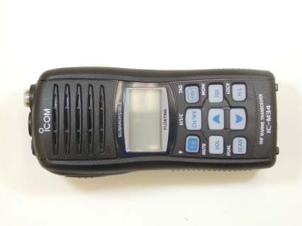
Click to zoom
Application Details
- Equipment Class
- TNF - Licensed Non-Broadcast Transmitter Held to Face
- Date of Grant
- Dec 05, 2006
- Application Purpose
- Original Equipment
- Date of Application
- Dec 05, 2006
- Equipment Note
- VHF Marine Transceiver
- Frequency Range
- 156.05000000 - 157.42500000
- Company
- ICOM Incorporated
- Country
- Japan
Documents & Files
Document Text
Text extracted from the exhibit documents filed with the FCC. Open a document above to read the original.
Users Manual
i SAFETY TRAINING INFORMATION Your Icom radio generates RF electromagnetic energy during transmit mode. This radio is designed for and classified as“Occupational Use Only”, meaning it must be used only duringthe course of employment by individuals aware of the haz-ards, and the ways to minimize such hazards. This radio isNOT intended for use by the “General Population” in an un-controlled environment. This radio has been evaluated for compliance at the distance of 2.5 cm withthe FCC RF exposure limits for “Occupational Use Only”. In addition, your Icomradio complies with the following Standards and Guidelines with regard to RFenergy and electromagnetic energy levels and evaluation of such levels for ex-posure to humans: • FCC OET Bulletin 65 Edition 97-01 Supplement C, Evaluating Compliance with FCC Guidelines for Human Exposure to Radio Frequency Electro-magnetic Fields. • American National Standards Institute (C95.1-1992), IEEE Standard for Safety Levels with Respect to Human Exposure to Radio Frequency Elec-tromagnetic Fields, 3 kHz to 300 GHz. • American National Standards Institute (C95.3-1992), IEEE Recommended Practice for the Measurement of Potentially Hazardous ElectromagneticFields– RF and Microwave. • The following accessories are authorized for use with this product. Use of accessories other than those specified may result in RF exposure levelsexceeding the FCC requirements for wireless RF exposure.; Belt Clip (MB-109), Rechargeable Li-Ion Battery Pack (BP-252) and Alkaline BatteryCase (BP-251). To ensure that your expose to RF electromagnetic en- ergy is within the FCC allowable limits for occupationaluse, always adhere to the following guidelines: CAUTION WARNING • DO NOT operate the radio without a proper antenna attached, as this may damaged the radio and may also cause you to exceed FCC RF exposurelimits. A proper antenna is the antenna supplied with this radio by the man-ufacturer or antenna specifically authorized by the manufacturer for usewith this radio. • DO NOT transmit for more than 50% of total radio use time (“50% duty cycle”). Transmitting more than 50% of the time can cause FCC RF expo-sure compliance requirements to be exceeded. The radio is transmittingwhen the “TX indicator” lights red. You can cause the radio to transmit bypressing the “PTT” switch. • ALWAYS keep the antenna at least 2.5 cm (1 inch) away from the body when transmitting and only use the Icom belt-clips which are listed onpage 29 when attaching the radio to your belt, etc., to ensure FCC RF ex-posure compliance requirements are not exceeded. To provide the recipi-ents of your transmission the best sound quality, hold the antenna at least5 cm (2 inches) from your mouth, and slightly off to one side. The information listed above provides the user with the information needed tomake him or her aware of RF exposure, and what to do to assure that this radiooperates with the FCC RF exposure limits of this radio. Electromagnetic Interference/CompatibilityDuring transmissions, your Icom radio generates RF energy that can possiblycause interference with other devices or systems. To avoid such interference,turn off the radio in areas where signs are posted to do so. DO NOT operate the transmitter in areas that are sensitive to electromagnetic radiation such ashospitals, aircraft, and blasting sites.Occupational/Controlled UseThe radio transmitter is used in situations in which persons are exposed asconsequence of their employment provided those persons are fully aware ofthe potential for exposure and can exercise control over their exposure. ii IN CASE OF EMERGENCYIf your vessel requires assistance, contact other vessels andthe Coast Guard by sending a distress call on Channel 16. ❍ USING CHANNEL 16 DISTRESS CALL PROCEDURE1. “MAYDAY MAYDAY MAYDAY.”2. “THIS IS ...........................” (name of vessel)3. Your call sign or other indication of the ves- sel. 4. “LOCATED AT .....................” (your position)5. The nature of the distress and assistance re- quired. 6. Any other information which might facilitate the rescue. RECOMMENDATIONCLEAN THE TRANSCEIVER THOROUGHLY WITH FRESHWATER after exposure to saltwater, and dry it before opera- tion. Otherwise, the transceiver's keys, switches and con-trollers may become inoperable due to salt crystallization.NOTE: DO NOT wash the transceiver in water if there is any reason to suspect the waterproofing may not be effective. Forexample, in cases where the battery pack rubber seal is dam-aged, the transceiver/battery pack is cracked or broken, orhas been dropped, or when the battery pack is detached fromthe transceiver. FOREWORDThank you for purchasing this Icom product. The IC-M34 VHF MARINE TRANSCEIVER is designed and built with Icom’s state of the art technology and craftsmanship. With proper care thisproduct should provide you with years of trouble-free operation. IMPORTANTREAD ALL INSTRUCTIONS carefully and com- pletely before using the transceiver. SAVE THIS INSTRUCTION MANUAL— This in- struction manual contains important operating instructions forthe IC-M34. EXPLICIT DEFINITIONS FEATURES☞ Submersible construction Built tough to withstand the punishing marine environ-ment, the IC-M34’s submersible construction meets IPX7of the corresponding International Standard IEC 60529(2001) while using BP-251 (option) or BP-252. ☞ Floating on water Even when the supplied accessories isattached, the IC-M34 floats on water. • When third-party or counterfeit battery pack, strap, antenna, etc. is used, it maysink. ☞ Large, easy-to-read LCD With dimensions of 16(H) × 32(W) mm; 5 ⁄ 8 (H) × 1 1 ⁄ 4 (W) inch, the IC-M34’s function display is easy to read andshows operating conditions at a glance. Backlighting andcontrast can be adjusted to suit your preferences. ☞ Simple operation 9 large buttons on the front panel provide user-friendly op-eration. The independent volume and channel buttons arelocated on the front panel for convenient one-hand opera-tion. DEFINITION R WARN…
Text truncated - open the document above for the full version.
Cover Letter(s)
December 04, 2006 American Telecommunications Certification Body, Inc. 6731 Whittier Avenue Suite C110 McLean, VA 22101 USA Subject: Equipment Authorization under FCC 47 CFR, Parts 2, 80 (Marine in 156.050-157.425 MHz Band) - Non-Broadcast Radio Transceivers. Applicant: ICOM Incorporated Product: VHF Marine Transceiver Model: IC-M34 FCC ID: AFJ298700 Dear Sir/Madam, As appointed agent for ICOM Incorporated, we would like to submit the application to Federal Communications Commission for certification of the above product. Please review all files uploaded to ATCB upload site. If you have any queries, please do not hesitate to contact us by our TOLL FREE number: OUR TELEPHONE NO.: 1-877-765-4173 Yours truly, Tri Minh Luu, P. Eng., V.P., Engineering TML/JW Encl. UltraTech Group of Labs Ultratech’s Accreditations: 0685 31040/SIT C-1376 46390-2049 200093-0 SL2-IN-E-1119R 3000 Bristol Circle, Oakville, Ontario, Canada L6H 6G4 Tel.: (905) 829-1570 Fax.: (905) 829-8050 Website: www.ultratech-labs.com Email: [email protected]
ID Label/Location Info
IC-M34 Serial Seal Location Serial Seal SAR Warning Label
RF Exposure Info
VHF Marine Transceiver - IC-M34 (FCC ID: AFJ298700) FCC power thresholds: f GHz 900/f Face-held controlled d >= 2.5 cm 0.155 5,806 mW 0.15 6,000 mW 1. 900/f = face-held controlled 2. d is the distance to a person’s body. No evaluation required if power is below this threshold: f GHz P out 0.155 5,806 mW (or 11,613 mW with 50% duty cycle) RF conducted peak power measured = 5,140 mW User-based time-average factor = 50 % = 0.5 Antenna Gain = -15.50 dB Threshold for no SAR evaluation is 5,806 mW Transmitter power is 5,140 mW X 0.5 = 2,570 mW. Conclusion: No SAR evaluation required since Transmitter Power is below FCC power thresholds Distance from the antenna with the thinnest belt-clip (M/N: MB-109) mounted Antenna Information M/N: FA-SC58V Gain: -15.50 dB Type: Helical antenna Frequency range: 150 – 174 MHz Remark: The above information had been provided by the manufacturer
Test Report
VHF Marine Transceiver Model No.: IC-M34 FCC ID: AFJ298700 Applicant: ICOM Incorporated 1-1-32, Kamiminami, Hirano-ku Osaka Japan, 547-0003 Tested in Accordance With Federal Communications Commission (FCC) 47 CFR, Part 2, Part 80 (Marine in 156.050-157.425 MHz) UltraTech's File No.: ICOM-138F80 This Test report is Issued under the Authority of Tri M. Luu, Professional Engineer, Vice President of Engineering UltraTech Group of Labs Date: December 04, 2006 Report Prepared by: JaeWook Choi Issued Date: December 04, 2006 Tested by: Wayne Wu, EMC/RFI Technician Hung Trinh, EMC/RFI Technician Test Dates: November 06 ~ November 09, 2006 The results in this Test Report apply only to the sample(s) tested, and the sample tested is randomly selected. This report must not be used by the client to claim product endorsement by NVLAP or any agency of the US Government. UltraTech 3000 Bristol Circle, Oakville, Ontario, Canada, L6H 6G4 Tel.: (905) 829-1570 Fax.: (905) 829-8050 Website: www.ultratech-labs.com , Email: [email protected], Email: [email protected] 0685 31040/SIT C-1376 46390-2049 200093-0 SL2-IN-E-1119R FCC Parts 2, 80 (Marine in 156.050-157.425 MHz), Non-Broadcast Radio Transceivers Contents i VHF Marine Transceiver, Model IC-M34 FCC ID: AFJ298700 ULTRATECH GROUP OF LABS File #: ICOM-138F80 3000 Bristol Circle, Oakville, Ontario, Canada L6H 6G4 December 04, 2006 Tel. #: 905-829-1570, Fax. #: 905-829-8050, Email: [email protected] , Website: http://www.ultratech-labs.com All test results contained in this engineering test report are traceable to National Institute of Standards and Technology (NIST) TABLE OF CONTENTS EXHIBIT 1. SUBMITTAL CHECK LIST........................................................................................................................ 1 EXHIBIT 2. INTRODUCTION ......................................................................................................................................... 2 2.1. SCOPE......................................................................................................................................................................... 2 2.2. RELATED SUBMITTAL(S)/GRANT(S) ................................................................................................................... 2 2.3. NORMATIVE REFERENCES ................................................................................................................................... 2 EXHIBIT 3. PERFORMANCE ASSESSMENT .............................................................................................................. 3 3.1. CLIENT INFORMATION .......................................................................................................................................... 3 3.2. EQUIPMENT UNDER TEST (EUT) INFORMATION.............................................................................................. 3 3.3. EUT’S TECHNICAL SPECIFICATIONS ..................................................................................................................4 3.4. LIST OF EUT’S PORTS ............................................................................................................................................. 5 3.5. ANCILLARY EQUIPMENT ...................................................................................................................................... 5 EXHIBIT 4. EUT OPERATING CONDITIONS AND CONFIGURATIONS DURING TESTS ............................... 6 4.1. CLIMATE TEST CONDITIONS ................................................................................................................................ 6 4.2. OPERATIONAL TEST CONDITIONS & ARRANGEMENT FOR TEST SIGNALS .............................................. 6 EXHIBIT 5. SUMMARY OF TEST RESULTS ............................................................................................................... 7 5.1. LOCATION OF TESTS .............................................................................................................................................. 7 5.2. APPLICABILITY & SUMMARY OF EMC EMISSION TEST RESULTS ............................................................... 7 5.3. MODIFICATIONS INCORPORATED IN THE EUT FOR COMPLIANCE PURPOSES......................................... 8 5.4. DEVIATION OF STANDARD TEST PROCEDURES .............................................................................................. 8 EXHIBIT 6. MEASUREMENTS, EXAMINATIONS & TEST DATA FOR EMC EMISSIONS ............................... 9 6.1. TEST PROCEDURES ................................................................................................................................................. 9 6.2. MEASUREMENT UNCERTAINTIES....................................................................................................................... 9 6.3. MEASUREMENT EQUIPMENT USED .................................................................................................................... 9 6.4. ESSENTIAL/PRIMARY FUNCTIONS AS DECLARED BY THE MANUFACTURER ......................................... 9 6.5. RF POWER OUTPUT [§§ 2.1046 & 80.215] ............................................................................................................ 10 6.6. FREQUECNY STABILITY [§§ 2.1055 & 80.209] ................................................................................................... 12 6.7. AUDIO FREQUENCY RESPONSE [§§ 2.1047(A) & 80.213(E)]............................................................................. 15 6.8. MODULATION LIMITING [§ 2.1047(B)] ............................................................................................................... 18 6.9. EMISSION MASK [§§ 2.1049 & 80.211] ................................................................................................................. 21 6.10. TRANSMITTER ANTENNA POWER SPURIOUS/HARMONIC CONDUCTED EMISSIONS [§§ 80.211(F)(3)]..........…
Text truncated - open the document above for the full version.
Test Setup Photos
Test Setup Photographs – ICOM VHF Marine Transceiver (M/N: IC-M34)
Contact Information
Applicant
Tatsuo Yano(General Manager of QA Department)
Technical Contact
Test Firm
UltraTech Engineering Labs Inc.Tri Luu
Technical Specifications
| # | Rule Parts | Frequency Range | Power Output | Emission | Tolerance |
|---|---|---|---|---|---|
| 2 | 8 | 156.05 MHz - 157.425 MHz | 1 W | 16K03GE | 10 ppm |
Other Applications from ICOM Incorporated

AFJ453700
Jul 23, 2026Mobile Transceiver
Equipment Class
DTS - Digital Transmission System
AFJ452000
Jun 02, 2026VHF DIGITAL TRANSCEIVER
Equipment Class
TNF - Licensed Non-Broadcast Transmitter Held to Face
AFJ452100
May 12, 2026UHF DIGITAL TRANSCEIVER
Equipment Class
TNF - Licensed Non-Broadcast Transmitter Held to Face
AFJ444500
Sep 12, 2024Scanning Receiver
Equipment Class
CSR - Scanning Receiver
AFJ410900
Jul 09, 2024Linear Amplifier
Equipment Class
AMP - Amplifier