AFJ334000VHF Marine Transceiver
ICOM Incorporated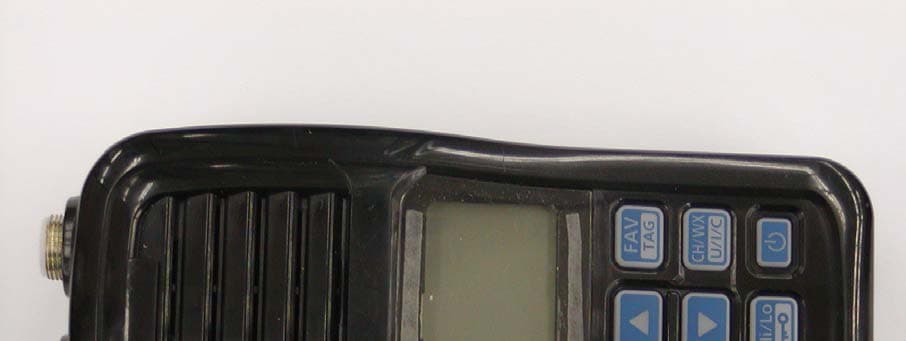
Click to zoom
Application Details
- Equipment Class
- TNF - Licensed Non-Broadcast Transmitter Held to Face
- Date of Grant
- Feb 14, 2011
- Application Purpose
- Original Equipment
- Date of Application
- Feb 06, 2011
- Equipment Note
- VHF Marine Transceiver
- Frequency Range
- 156.02500000 - 157.42500000
- Company
- ICOM Incorporated
- Country
- Japan
Documents & Files
Document Text
Text extracted from the exhibit documents filed with the FCC. Open a document above to read the original.
Users Manual
INSTRUCTION MANUAL iM24VHF MARINE TRANSCEIVER This device complies with Part 15 of the FCC Rules. Operation is subject to the condition that this device does not cause harmful interference. i Your Icom radio generates RF electromagnetic energy during transmit mode. This radio is designed for and classified as “General Population Use” in an uncontrolled environment. This radio has been evaluated for compliance at the distance of 2.5 cm (1 inch) with the FCC RF exposure limits for “ Gen- eral Population Use ”. In addition, your Icom radio complies with the following Standards and Guidelines with regard to RF energy and electromagnetic energy levels and evaluation of such levels for exposure to humans: • FCC OET Bulletin 65 Edition 01-01 Supplement C, Evaluating Compli-ance with FCC Guidelines for Human Exposure to Radio Frequency Electromagnetic Fields. • American National Standards Institute (C95.1-1992), IEEE Standard for Safety Levels with Respect to Human Exposure to Radio Frequency Electromagnetic Fields, 3 kHz to 300 GHz. • American National Standards Institute (C95.3-1992), IEEE Recom-mended Practice for the Measurement of Potentially Hazardous Electro-magnetic Fields– RF and Microwave. • The following accessories are authorized for use with this product. Use of accessories other than those specifi ed may result in RF exposure levels exceeding the FCC requirements for wireless RF exposure.; Belt Clip (MB-124), Rechargeable Li-Ion Battery Pack (BP-266). To ensure that your expose to RF electromagnetic en-ergy is within the FCC allowable limits for general popu-lation use, always adhere to the following guidelines: • DO NOT operate the radio without a proper antenna attached, as this may damaged the radio and may also cause you to exceed FCC RF ex-posure limits. A proper antenna is the antenna supplied with this radio by the manufacturer or antenna specifi cally authorized by the manufacturer for use with this radio. • DO NOT transmit for more than 50% of total radio use time (“50% duty cycle”). Transmitting more than 50% of the time can cause FCC RF expo-sure compliance requirements to be exceeded. The radio is transmitting when the “transmit indicator” appears on the LCD. You can cause the radio to transmit by pressing the “PTT” switch. • ALWAYS keep the antenna at least 2.5 cm (1 inch) away from the body when transmitting and only use the Icom belt clip which is listed on p. 28 when attaching the radio to your belt, etc., to ensure FCC RF exposure compliance requirements are not exceeded. To provide the recipients of your transmission the best sound quality, hold the antenna at least 5 cm (2 inches) from your mouth, and slightly off to one side. The information listed above provides the user with the information needed to make him or her aware of RF exposure, and what to do to assure that this radio operates with the FCC RF exposure limits of this radio. Electromagnetic Interference/CompatibilityDuring transmissions, your Icom radio generates RF energy that can possibly cause interference with other devices or systems. To avoid such interference, turn off the radio in areas where signs are posted to do so. DO NOT operate the transmitter in areas that are sensitive to electromagnetic radiation such as hospitals, aircraft, and blasting sites. i SAFETY TRAINING INFORMATION ii IN CASE OF EMERGENCY RECOMMENDATION If your vessel requires assistance, contact other vessels and the Coast Guard by sending a distress call on Channel 16. ❍ USING CHANNEL 16 DISTRESS CALL PROCEDURE 1. “MAYDAY MAYDAY MAYDAY.”2. “THIS IS .................. ” (name of vessel)3. Your call sign or other indication of the ves-sel. 4. “LOCATED AT ............... ” (your position)5. The nature of the distress and assistance required. 6. Any other information which might facilitate the rescue. CLEAN THE TRANSCEIVER THOROUGHLY WITH FRESH WATER after exposure to saltwater, and dry it before operat- ing. Otherwise, the transceiver's keys, switches and control-lers may become unusable due to salt crystallization.NOTE: DO NOT submerge the transceiver in water if there is any reason to suspect the waterproof protection may not be effective. For example, in cases where the battery cover or [DC] jack cap rubber seal is damaged, the transceiver/battery cover/[DC] jack cap is cracked or broken, or the transceiver has been dropped, or when the battery cover, antenna or DC Jack cap are detached from the transceiver. B P - 2 6 6 B P - 2 6 6 B P - 2 6 6 FOREWORDThank you for purchasing this Icom radio. The IC-M24 VHF MARINE TRANSCEIVER is designed and built with Icom’s state of the art technology and craftsmanship. With proper care this radio should provide you with years of trouble-free operation. IMPORTANTREAD ALL INSTRUCTIONS carefully and com- pletely before using the transceiver. SAVE THIS INSTRUCTION MANUAL— This instruction manual contains important operating instructions for the IC-M24. EXPLICIT DEFINITIONS WORD DEFINITION R DANGER! Personal death, serious injury or an explo-sion may occur. R WARNING! Personal injury, fire hazard or electric shock may occur. CAUTION Equipment damage may occur. NOTE If disregarded, only inconvenience. No risk of personal injury, fi re or electric shock. FEATURES☞ Floats on water The transceiver floats in fresh or salt water even when the supplied acces-sories are attached. • When a third-party battery pack, strap, an- tenna, etc. is used, it may sink. ☞ Floats and fl ashes An LED sends out intermittent light from a transparent section on the bottom of the radio, while floating in the water.As the LED light stands out in the dark (like a flashing fishing float), the radio can be easily retrieved from the water.This function works even when the radio is turned OFF. iii iv R WARNING! NEVER connect the transceiver to an AC outlet. This may pose a fi re hazard or result in an electric shock. R WARNING! NEVER hold the transceiver so that the antenna is closer than 2.5 cm (1 inch) from exposed parts o…
Text truncated - open the document above for the full version.
Cover Letter(s)
January 11, 2011 Ultratech Engineering Labs, Inc. 3000 Bristol Circle Oakville, Ontario L6H 6G4 Subject: Equipment Authorization under FCC 47 CFR, Parts 2, 80 (Marine in 156.025-157.425 MHz Band) - Non-Broadcast Radio Transceivers. Applicant: ICOM Incorporated Product: VHF Marine Transceiver Model: IC-M24 FCC ID: AFJ334000 Dear Sir/Madam, As appointed agent for ICOM Incorporated, We would like to submit FCC certification application of the above product. Please find report and application documents uploaded your E-filing site. If you have any queries, please do not hesitate to contact us. Yours truly, Dharmajit Solanki Dharmajit Solanki Authorized Agent UltraTech Group of Labs FCC TCB & IC CB Ultratech’s Accreditations: 0685 FCC 91038 1309 46390-2049 NVLAP Lab Code 200093-0 SL2-IN-E-1119R Korea KCC-RRL CA2049 3000 Bristol Circle, Oakville, Ontario, Canada L6H 6G4 Tel.: (905) 829-1570 Fax.: (905) 829-8050 Website: www.ultratech-labs.com Email: [email protected]
ID Label/Location Info
IC-M24 Serial Seal Location Serial Seal
RF Exposure Info
i Your Icom radio generates RF electromagnetic energy during transmit mode. This radio is designed for and classified as “General Population Use” in an uncontrolled environment. This radio has been evaluated for compliance at the distance of 2.5 cm (1 inch) with the FCC RF exposure limits for “ Gen- eral Population Use ”. In addition, your Icom radio complies with the following Standards and Guidelines with regard to RF energy and electromagnetic energy levels and evaluation of such levels for exposure to humans: • FCC OET Bulletin 65 Edition 01-01 Supplement C, Evaluating Compli-ance with FCC Guidelines for Human Exposure to Radio Frequency Electromagnetic Fields. • American National Standards Institute (C95.1-1992), IEEE Standard for Safety Levels with Respect to Human Exposure to Radio Frequency Electromagnetic Fields, 3 kHz to 300 GHz. • American National Standards Institute (C95.3-1992), IEEE Recom-mended Practice for the Measurement of Potentially Hazardous Electro-magnetic Fields– RF and Microwave. • The following accessories are authorized for use with this product. Use of accessories other than those specifi ed may result in RF exposure levels exceeding the FCC requirements for wireless RF exposure.; Belt Clip (MB-124), Rechargeable Li-Ion Battery Pack (BP-266). To ensure that your expose to RF electromagnetic en-ergy is within the FCC allowable limits for general popu-lation use, always adhere to the following guidelines: • DO NOT operate the radio without a proper antenna attached, as this may damaged the radio and may also cause you to exceed FCC RF ex-posure limits. A proper antenna is the antenna supplied with this radio by the manufacturer or antenna specifi cally authorized by the manufacturer for use with this radio. • DO NOT transmit for more than 50% of total radio use time (“50% duty cycle”). Transmitting more than 50% of the time can cause FCC RF expo-sure compliance requirements to be exceeded. The radio is transmitting when the “transmit indicator” appears on the LCD. You can cause the radio to transmit by pressing the “PTT” switch. • ALWAYS keep the antenna at least 2.5 cm (1 inch) away from the body when transmitting and only use the Icom belt clip which is listed on p. 28 when attaching the radio to your belt, etc., to ensure FCC RF exposure compliance requirements are not exceeded. To provide the recipients of your transmission the best sound quality, hold the antenna at least 5 cm (2 inches) from your mouth, and slightly off to one side. The information listed above provides the user with the information needed to make him or her aware of RF exposure, and what to do to assure that this radio operates with the FCC RF exposure limits of this radio. Electromagnetic Interference/CompatibilityDuring transmissions, your Icom radio generates RF energy that can possibly cause interference with other devices or systems. To avoid such interference, turn off the radio in areas where signs are posted to do so. DO NOT operate the transmitter in areas that are sensitive to electromagnetic radiation such as hospitals, aircraft, and blasting sites. i SAFETY TRAINING INFORMATION
Test Report
VHF Marine Transceiver Model No.: IC-M24 FCC ID: AFJ334000 Applicant: ICOM Incorporated 1-1-32, Kamiminami, Hirano-ku, Osaka Japan, 547-0003 Tested in Accordance With Federal Communications Commission (FCC) 47 CFR, Part 2, Part 80 (Marine in 156.025-157.425 MHz) UltraTech's File No.: ICOM-265_FCC80 This Test report is Issued under the Authority of Tri M. Luu, Professional Engineer, Vice President of Engineering UltraTech Group of Labs Date: January 11, 2011 Report Prepared by: Dharmajit Solanki Issued Date: January 11, 2011 Tested by: Wayne W u, RF Technician Test Dates: December 28, 2010 – January 5, 2011 The results in this Test Report apply only to the sample(s) tested, and the sample tested is randomly selected. This report must not be used by the client to claim product endorsement by NVLAP or any agency of the US Government. UltraTech 3000 Bristol Circle, Oakville, Ontario, Canada, L6H 6G4 Tel.: (905) 829-1570 Fax.: (905) 829-8050 Website: www.ultratech-labs.com , Email: [email protected], Email: [email protected] FCC Korea KCC-RRL 91038 1309 46390-2049 NVLAP Lab Code 200093-0 SL2-IN-E-1119R CA2049 FCC Parts 2, 80 (Marine in 156.025-157.425 MHz), Non-Broadcast Radio Transceivers Contents i VHF Marine Transceiver, Model IC-M24 FCC ID: AFJ334000 ULTRATECH GROUP OF LABS File #: ICOM-265_FCC80 3000 Bristol Circle, Oakville, Ontario, Canada L6H 6G4 January 11, 2011 Tel. #: 905-829-1570, Fax. #: 905-829-8050, Email: [email protected] , Website: http://www.ultratech-labs.com All test results contained in this engineering test report are traceable to National Institute of Standards and Technology (NIST) TABLE OF CONTENTS EXHIBIT 1. INTRODUCTION ......................................................................................................................................... 1 1.1. SCOPE......................................................................................................................................................................... 1 1.2. RELATED SUBMITTAL(S)/GRANT(S) ................................................................................................................... 1 1.3. NORMATIVE REFERENCES ................................................................................................................................... 1 EXHIBIT 2. PERFORMANCE ASSESSMENT .............................................................................................................. 2 2.1. CLIENT INFORMATION .......................................................................................................................................... 2 2.2. EQUIPMENT UNDER TEST (EUT) INFORMATION.............................................................................................. 2 2.3. EUT’S TECHNICAL SPECIFICATIONS ..................................................................................................................3 2.4. LIST OF EUT’S PORTS ............................................................................................................................................. 3 2.5. ANCILLARY EQUIPMENT ...................................................................................................................................... 3 EXHIBIT 3. EUT OPERATING CONDITIONS AND CONFIGURATIONS DURING TESTS ............................... 4 3.1. CLIMATE TEST CONDITIONS ................................................................................................................................ 4 3.2. OPERATIONAL TEST CONDITIONS & ARRANGEMENT FOR TEST SIGNALS .............................................. 4 EXHIBIT 4. SUMMARY OF TEST RESULTS ............................................................................................................... 5 4.1. LOCATION OF TESTS .............................................................................................................................................. 5 4.2. APPLICABILITY & SUMMARY OF EMC EMISSION TEST RESULTS ............................................................... 5 4.3. MODIFICATIONS INCORPORATED IN THE EUT FOR COMPLIANCE PURPOSES......................................... 5 4.4. DEVIATION OF STANDARD TEST PROCEDURES .............................................................................................. 5 EXHIBIT 5. TEST DATA................................................................................................................................................... 6 5.1. RF POWER OUTPUT [§ 2.1046 & 80.215] ................................................................................................................ 6 5.2. FREQUECNY STABILITY [§ 80.209 & § 2.1055] .................................................................................................... 8 5.3. MODULATION LIMITING [§ 80.213 & § 2.1047(B)] ............................................................................................. 10 5.4. FREQUENCY RESPONSE OF THE AUDIO LOW PASS FILTER [§ 80.213(E) & 2.1047(A)]............................. 13 5.5. EMISSION MASK [§ 80.205, § 80.211 & § 2.1049] ................................................................................................. 16 5.6. TRANSMITTER ANTENNA POWER SPURIOUS/HARMONIC CONDUCTED EMISSIONS [§ 80.211(F)(3)]. 28 5.7. TRANSMITTER SPURIOUS/HARMONIC RADIATED EMISSIONS [§ 80.211(F)(3)] ....................................... 37 EXHIBIT 6. TEST INSTRUMENTS & MEASUREMENT UNCERTAINTY (K=2, 95% CONFIDENCE LEVEL) 39 6.1. RADIATED EMISSION MEASUREMENT UNCERTAINTY ............................................................................... 39 EXHIBIT 7. MEASUREMENT METHODS .................................................................................................................. 40 7.1. CONDUCTED POWER MEASUREMENTS........................................................................................................... 40 7.2. RADIATED POWER MEASUREMENTS (ERP & EIRP) USING SUBSTITUTION METHOD ........…
Text truncated - open the document above for the full version.
Test Setup Photos
ANNEX 1 - TEST SETUP PHOTOGRAPHS ICOM Incorporated VHF Marine Transceiver, M/N: IC-M24 FCC ID: AFJ334000, IC: 202D-334000 Plot #1: Tx Radiated Emission Test Setup ANNEX 1 - TEST SETUP PHOTOGRAPHS ICOM Incorporated VHF Marine Transceiver, M/N: IC-M24 FCC ID: AFJ334000, IC: 202D-334000 Plot #2: Tx Radiated Emission Test Setup ANNEX 1 - TEST SETUP PHOTOGRAPHS ICOM Incorporated VHF Marine Transceiver, M/N: IC-M24 FCC ID: AFJ334000, IC: 202D-334000 Plot #3: Tx Radiated Emission Test Setup
Contact Information
Applicant
Atsushi Tomiyama(General Manager)
Technical Contact
UltraTech Engineering Labs Inc.Dharmajit Solanki
[email protected]905-829-1570
3000 Bristol Circle · Oakville, ON · Canada
Test Firm
UltraTech Engineering Labs Inc.Tri Luu
Technical Specifications
| # | Rule Parts | Frequency Range | Power Output | Emission | Tolerance |
|---|---|---|---|---|---|
| 2 | 8 | 156.025 MHz - 157.425 MHz | 1 W | 16K0G3E | 10 ppm |
Other Applications from ICOM Incorporated

AFJ453700
Jul 23, 2026Mobile Transceiver
Equipment Class
DTS - Digital Transmission System
AFJ452000
Jun 02, 2026VHF DIGITAL TRANSCEIVER
Equipment Class
TNF - Licensed Non-Broadcast Transmitter Held to Face
AFJ452100
May 12, 2026UHF DIGITAL TRANSCEIVER
Equipment Class
TNF - Licensed Non-Broadcast Transmitter Held to Face
AFJ444500
Sep 12, 2024Scanning Receiver
Equipment Class
CSR - Scanning Receiver
AFJ410900
Jul 09, 2024Linear Amplifier
Equipment Class
AMP - Amplifier