AFJ348400Dual Band Transceiver
ICOM Incorporated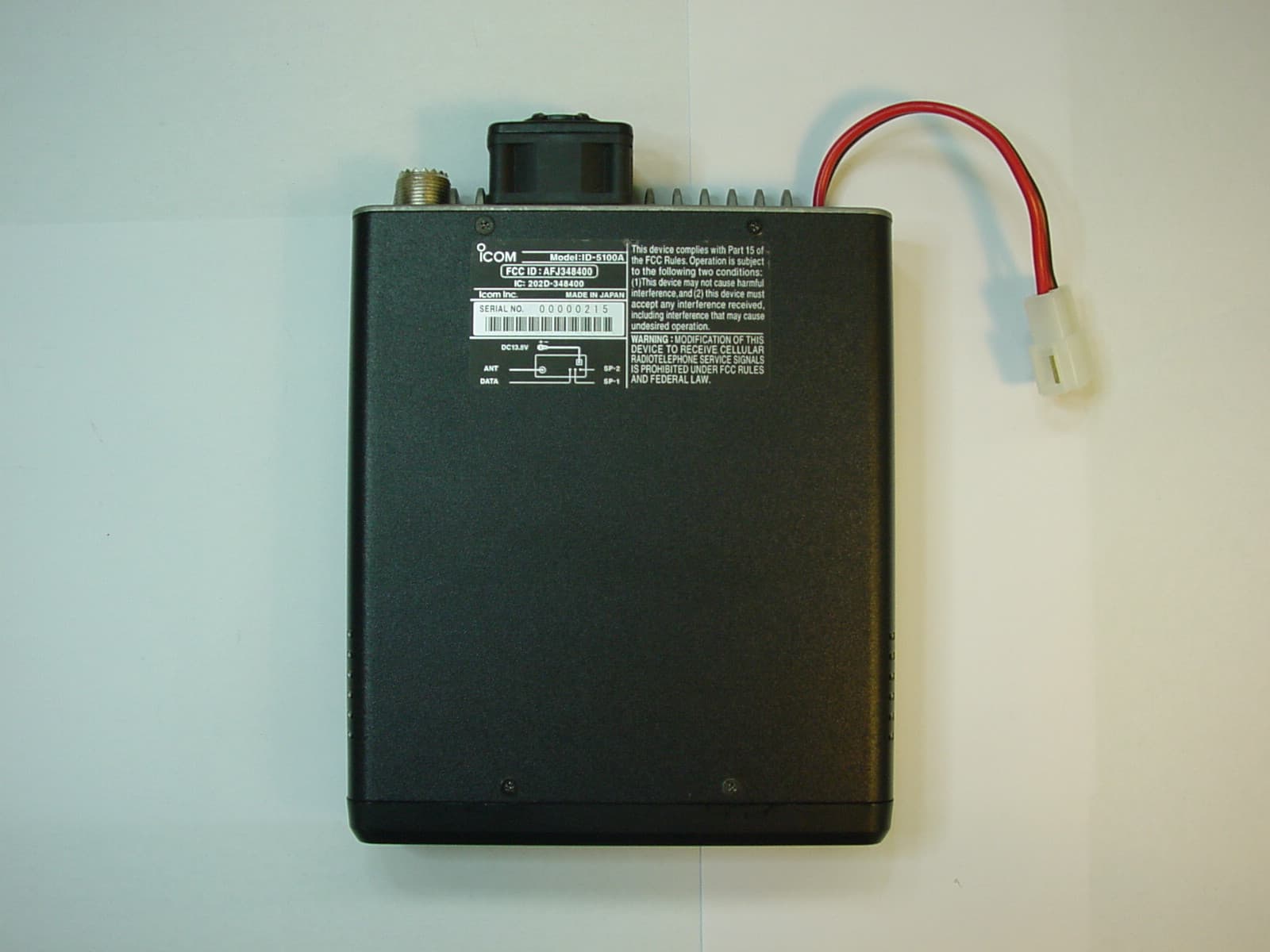
Click to zoom
Application Details
- Equipment Class
- CSR - Scanning Receiver
- Date of Grant
- Mar 26, 2014
- Application Purpose
- Original Equipment
- Date of Application
- Mar 26, 2014
- Equipment Note
- Dual Band Transceiver
- Frequency Range
- 375.00000000 - 550.00000000
- Company
- ICOM Incorporated
- Country
- Japan
Documents & Files
Document Text
Text extracted from the exhibit documents filed with the FCC. Open a document above to read the original.
Users Manual
This device complies with Part 15 of the FCC Rules. Operation is subject to the following two conditions: (1) this device may not cause harmful interference, and (2) this device must accept any interference received, including interference that may cause undesired operation. WARNING: MODIFICATION OF THIS DEVICE TO RECEIVE CEL- LULAR RADIOTELEPHONE SERVICE SIGNALS IS PROHIBITED UNDER FCC RULES AND FEDERAL LAW. BASIC INSTRUCTIONS New2001 ID-5100A DUAL BAND TRANSCEIVER ID-5100E i New2001New2001 FOREWORD Thank you for purchasing this fine Icom product. The ID- 5100A and ID-5100E DUAL BAND TRANSCEIVER are designed and build with Icom’s superior technology and craftsmanship combining traditional analog technologies with the new digital technology, Digital Smart Technologies for Amateur Radio (D- STAR), for a balanced package. With proper care, this product should provide you with years of trouble-free operation. We thank you for making your ID-5100A or ID-5100E your transceiver of choice, and hope you agree with Icom’s philos- ophy of “technology first.” Many hours or research and devel- opment went into the design of your ID-5100A or ID-5100E. EXPLICIT DEFINITIONS WORDDEFINITION R DANGER! Personal death, serious injury or an ex- plosion may occur. R WARNING! Personal injury, fire hazard or electric shock may occur. CAUTIONEquipment damage may occur. NOTE Recommended for optimum use. No risk of personal injury, fire or electric shock. IMPORTANT READ ALL INSTRUCTIONS carefully and completely before using the transceiver. SAVE THIS INSTRUCTION MANUAL— This in- struction manual contains basic operating instructions for the ID-5100A/ID-5100E. Icom, Icom Inc. and the Icom logo are registered trademarks of Icom Incorporated (Japan) in Japan, the United States, the United King- dom, Germany, France, Spain, Russia and/or other countries. Adobe and Adobe Reader are either registered trademarks or trade- marks of Adobe Systems Incorporated, in the United States and/or other countries. Microsoft, Windows and Windows Vista are registered trademarks of Microsoft Corporation in the United States and/or other countries. The Bluetooth ® work mark and logos are registered trademarks owned by Bluetooth SIG, Inc. and any use of such marks by Icom inc. is under license. All other products or brands are registered trademarks or trademarks of their respective holders. New2001New2001 ii SUPPLIED ACCESSORIES The following accessories are supplied with the transceiver. DC power cable Controller cable (3.5 m:11.4 ft) Microphone (HM-207) CD ( Instruction manual [Full instructions]) Operating guide ( Includes the CS-5100 CLONING SOFTWARE) Spare fuse (FGB 20 A) Microphone hanger DWhen using the GPS receiver • GPS signals cannot pass through metal objects. When us- ing the ID-5100A or ID-5100E inside a vehicle, you may not receive GPS signals. We recommend you use it near a win- dow. Please avoid the areas: 1. where it will block the driver’s view. 2. where the air bags could deploy. 3. where it becomes a driving obstacle. • The Global Positioning System (GPS) is built and operated by the U.S. Department of Defence. The Department is re- sponsible for accuracy and maintenance of the system. Any changes by the Department may affect the accuracy and function of the GPS system. • When the GPS receiver is activated, please do not cover the remote controller with anything that will block the satel- lite signals. • The GPS receiver may not work if used in the following loca- tions: 1. Tunnels or high-rise buildings 2. Underground parking lots 3. Under a bridge or viaduct 4. In remote forested areas 5. Under bad weather conditions (rainy or cloudy day) IMPORTANT NOTES iii New2001New2001 Touch screen precautions D Briefly touching the controller’s touch operates the function. • The touch screen may not properly work when LCD protec- tion film or sheet is attached. • Touching the screen with finger nails, sharp topped object and so on, or touching the screen hard may damage the screen. • Tablet PC’s operations such as flick input, pinch in and pinch out cannot be performed with this touch screen. Touch screen maintenance D • If the touch screen becomes dusty or dirty, wipe it clean with a soft, dry cloth. • When you wipe the touch screen, be careful not to push it too hard or scratch it with finger nails. Otherwise you may damage the touch screen. Touch operation D (Short touch): If the display is touched briefly, one short beep sounds. (Long touch): If the display is touched for 1 second, one short and one long beep sound. • After the beep, the operation is enabled. In the instruction manual, the touch operation is described as shown below. If the display is touched briefly, one short beep sounds. If the display is touched for 1 second, one short and one long beep sound. About the Touch area D Areas you can touch for various operations are shown to the right. • This page describes the main operations of the touch screen. See the instruction manual for other operations. ABOUT THE TOUCH SCREEN iv ID-5100 Function menu selection: Displays the Function menu list: Displays the QUICK Menu: Function menu operations • The following operations are examples. Sets MAIN band to the right side: Sets MAIN band to the right side: Dual or Single band display selection: • In the Single band, touch [B] to set the B band as the MAIN band. Displays the DR screen: • D-STAR settings can easily be made. Home CH selection: • Selects the Home CH that you set in the QUICK Menu. Home CH setting: Displays the Menu screen: Cancels “MHz” tuning: Tuning step selection: Displays the Memory Write window: Writes to a blank CH: Scan type selection: Starts a scan: • The last used scan starts. Dual or Single band display selection: Operating mode selection: “MHz” tuning selection: Operating band selection: TX power selection: • MAIN band: Used for TX or radio’s settings • SUB band: Used for the Dualwatch operation ABOUT THE TOUCH SCREEN (Continued) Displays the Monit…
Text truncated - open the document above for the full version.
Cover Letter(s)
March 12, 2014 Ultratech Engineering Labs, Inc. 3000 Bristol Circle Oakville, Ontario L6H 6G4 Subject: Certification Testing in Accordance with FCC CFR 47, Part 15, Subpart B - Scanning Receiver Applicant: ICOM Incorporated Product: Dual Band Transceiver Model: IC-5100A FCC ID: AFJ348400 Dear Sir/Madam: As appointed agent for ICOM Incorporated, we submit the application for certification of the above product. Please review all files uploaded to your electronic filing site. Please note that the above radio is Amateur transmitter and Scanning receiver. Since Amateur radio is exempted for FCC certification requirement, we submitted only scanning receiver portion for approval in this filing. An optional Bluetooth unit (UT-133, FCC ID: AFJ356100) which can be plugged into this radio as described in the user manual will be FCC/IC certified and the radio labeled as shown in the Label & Location appendix of this filing. If you have any queries, please do not hesitate to contact us: Yours truly, Dharmajit Solanki Dharmajit Solanki Authorized Agent UltraTech Group of Labs FCC TCB & IC CB Ultratech’s Accreditations: 0685 91038 1309 46390-2049 NVLAP LAB CODE 200093-0 SL2-IN-E-1119R Korea KCC-RRA CA2049 TL363_B TPTDP DA1300 3000 Bristol Circle, Oakville, Ontario, Canada L6H 6G4 Tel.: (905) 829-1570 Fax.: (905) 829-8050 Website: www.ultratech-labs.com Email: [email protected]
ID Label/Location Info
Contains FCC ID : AFJ356100 Contains IC : 202D - 356100
Test Report
Dual Band Transceiver Model No.: IC-5100A FCC ID: AFJ348400 Applicant: ICOM Incorporated 1-1-32, Kamiminami, Hirano-ku Osaka, Japan, 547-0003 Tested in Accordance With Federal Communications Commission (FCC) 47 CFR, Part 15, Subpart B, Scanning Receivers UltraTech's File No.: ICOM-357Q_FCC15.121 This Test report is Issued under the Authority of Tri M. Luu, BASc Vice President of Engineering UltraTech Group of Labs Date: March 12, 2014 Report Prepared by: Dharmajit Solanki Issued Date: March 12, 2014 Tested by: Wei Wu and Hien Luu Test Dates: March 4 to 6, 2014 The results in this Test Report apply only to the sample(s) tested, and the sample tested is randomly selected. This report must not be used by the client to claim product endorsement by NVLAP or any agency of the US Government. UltraTech 3000 Bristol Circle, Oakville, Ontario, Canada, L6H 6G4 Tel.: (905) 829-1570 Fax.: (905) 829-8050 Website: www.ultratech-labs.com , Email: [email protected], Email: [email protected] Korea KCC-RRA 91038 1309 46390-2049 NVLAP LAB CODE 200093-0 SL2-IN-E- 1119R CA2049 TL363_B TPTDP DA1300 FCC Part 15, Subpart B, Section 15.121 Contents i Dual Band Transceiver, M/N: IC-5100A FCC ID: AFJ348400 ULTRATECH GROUP OF LABS File #: ICOM-357Q_FCC15.121 3000 Bristol Circle, Oakville, Ontario, Canada L6H 6G4 March 12, 2014 Tel. #: 905-829-1570, Fax. #: 905-829-8050, Email: [email protected] , Website: http://www.ultratech-labs.com All test results contained in this engineering test report are traceable to National Institute of Standards and Technology (NIST) TABLE OF CONTENTS EXHIBIT 1. INTRODUCTION ......................................................................................................................................... 1 1.1. SCOPE......................................................................................................................................................................... 1 1.2. RELATED SUBMITTAL(S)/GRANT(S) .................................................................................................................. 1 1.3. NORMATIVE REFERENCES ................................................................................................................................... 1 EXHIBIT 2. PERFORMANCE ASSESSMENT .............................................................................................................. 2 2.1. CLIENT INFORMATION .......................................................................................................................................... 2 2.2. EQUIPMENT UNDER TEST (EUT) INFORMATION ............................................................................................ 2 2.3. EUT’S TECHNICAL SPECIFICATIONS ................................................................................................................. 3 2.4. LIST OF EUT’S PORTS............................................................................................................................................. 3 2.5. ANCILLARY EQUIPMENT ...................................................................................................................................... 3 EXHIBIT 3. EUT OPERATING CONDITIONS AND CONFIGURATIONS DURING TESTS ............................... 4 3.1. OPERATIONAL TEST CONDITIONS & ARRANGEMENT FOR TEST SIGNALS............................................. 4 EXHIBIT 4. SUMMARY OF TEST RESULTS ............................................................................................................... 5 4.1. LOCATION OF TESTS.............................................................................................................................................. 5 4.2. APPLICABILITY & SUMMARY OF EMC EMISSION TEST RESULTS ............................................................. 5 4.3. MODIFICATIONS REQUIRED FOR COMPLIANCE............................................................................................. 5 EXHIBIT 5. MEASUREMENTS, EXAMINATIONS & TEST DATA FOR EMC EMISSIONS............................... 6 5.1. TEST PROCEDURES................................................................................................................................................. 6 5.2. MEASUREMENT UNCERTAINTIES ...................................................................................................................... 6 5.3. MEASUREMENT EQUIPMENT USED ................................................................................................................... 6 5.4. POWER LINE CONDUCTED EMISSIONS [§ 15.107(A)] ...................................................................................... 7 5.5. RECEIVER ANTENNA POWER SPURIOUS/HARMONIC CONDUCTED EMISSIONS [§15.111(A)] ........... 10 5.6. SPURIOUS/HARMONIC RADIATED EMISSIONS FROM RECEIVER AND CLASS B UNINTENTIONAL RADIATORS (DIGITAL DEVICES) [§ 15.109(A)] ............................................................................................... 17 5.7. REQUIREMENTS FOR SCANNING RECEIVERS [§ 15.121].............................................................................. 22 5.8. SCANNING RECEIVERS CELLULAR BAND REJECTION [§ 15.121(B)] ........................................................ 25 EXHIBIT 6. TEST EQUIPMENTS LIST ....................................................................................................................... 27 EXHIBIT 7. MEASUREMENT UNCERTAINTY.........................................................................................................28 7.1. LINE CONDUCTED EMISSION MEASUREMENT UNCERTAINTY ................................................................ 28 7.2. RADIATED EMISSION MEASUREMENT UNCERTAINTY .............................................................................. 28 FCC Part 15, Subpart B, Section 15.121 Page 1 of 36 Dual Band Transceiver, M/N: IC-5100A FCC ID: AFJ348400 ULTRATECH GROUP OF LABS File #: ICOM-357Q_FCC15.121 3000 Bristol Circle, Oakville, Onta…
Text truncated - open the document above for the full version.
Test Setup Photos
ANNEX 1 – TEST SETUP PHOTOS Icom Incorporated Dual Band Transceiver, Model IC-5100A FCC ID: AFJ348400, IC: 202D-348400 A1 - 1 AC Power-line Conducted Emission ANNEX 1 – TEST SETUP PHOTOS Icom Incorporated Dual Band Transceiver, Model IC-5100A FCC ID: AFJ348400, IC: 202D-348400 A1 - 2 AC Power-line Conducted Emission ANNEX 1 – TEST SETUP PHOTOS Icom Incorporated Dual Band Transceiver, Model IC-5100A FCC ID: AFJ348400, IC: 202D-348400 A1 - 3 Radiated Emission at 3m Distance ANNEX 1 – TEST SETUP PHOTOS Icom Incorporated Dual Band Transceiver, Model IC-5100A FCC ID: AFJ348400, IC: 202D-348400 A1 - 4 Radiated Emission at 3m Distance
Contact Information
Applicant
Tatsuo Yano(General Manager of QA Department)
Test Firm
UltraTech Engineering Labs Inc.Tri Luu
Technical Specifications
| # | Rule Parts | Frequency Range | Power Output |
|---|---|---|---|
| 2 | 15B | 375 MHz - 550 MHz | - |
Other Applications from ICOM Incorporated

AFJ453700
Jul 23, 2026Mobile Transceiver
Equipment Class
DTS - Digital Transmission System
AFJ452000
Jun 02, 2026VHF DIGITAL TRANSCEIVER
Equipment Class
TNF - Licensed Non-Broadcast Transmitter Held to Face
AFJ452100
May 12, 2026UHF DIGITAL TRANSCEIVER
Equipment Class
TNF - Licensed Non-Broadcast Transmitter Held to Face
AFJ444500
Sep 12, 2024Scanning Receiver
Equipment Class
CSR - Scanning Receiver
AFJ410900
Jul 09, 2024Linear Amplifier
Equipment Class
AMP - Amplifier