AFJ349300VHF Marine Transceiver
ICOM Incorporated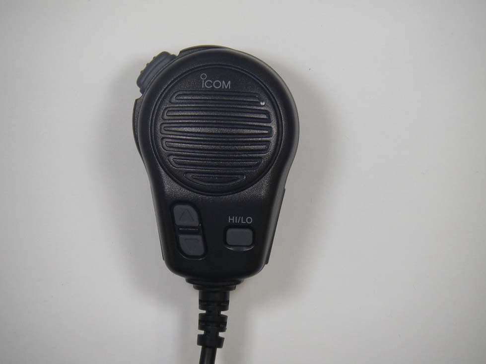
Click to zoom
Application Details
- Equipment Class
- TNB - Licensed Non-Broadcast Station Transmitter
- Date of Grant
- Nov 05, 2014
- Application Purpose
- Original Equipment
- Date of Application
- Nov 05, 2014
- Equipment Note
- VHF Marine Transceiver
- Frequency Range
- 156.52500000 - 156.52500000
- Company
- ICOM Incorporated
- Country
- Japan
Documents & Files
Document Text
Text extracted from the exhibit documents filed with the FCC. Open a document above to read the original.
Users Manual
INSTRUCTION MANUAL iM323 iM323G iM324 iM324G VHF MARINE TRANSCEIVER This device complies with Part 15 of the FCC Rules. Operation is subject to the condition that this device does not cause harmful interference. i FOREWORD Thank you for purchasing this Icom product. The IC-M323/ IC-M323G/IC-M324/IC-M324G v h f m a r i n e t r a n s c e i v e r is designed and built with Icom’s state of the art technology and craftsmanship. With proper care, this product should provide you with years of trouble-free operation. We appreciate you making the IC-M323, IC-M323G, IC-M324, or IC-M324G your radio of choice, and hope you agree with Icom’s philosophy of “technology first.” Many hours of research and development went into the de sign of your radio. FEATURES D ❍ Simple operation with large keys ❍ Easy to hear speaker ❍ Built-in DSC meets ITU Class D requirement ❍ Rugged waterproof construction ❍ Easy to make an individual DSC calls using the optional MA-500TR Class B AIS Transponder IMPORTANT READ ALL INSTRUCTIONS carefully and completely before using the transceiver. SAVE THIS INSTRUCTION MANUAL — This in- struction manual contains important operating instructions for the transceiver. EXPLICIT DEFINITIONS WORDDEFINITION RWARNING! Personal injury, fire hazard or electric shock may occur. CAUTION Equipment damage may occur. NOTE If disregarded, inconvenience only. No risk of personal injury, fire or electric shock. CLEAN THE TRANSCEIVER AND MICROPHONE THOR- OUGHLY WITH FRESH WATER after exposure to water including salt, otherwise, the keys and switch may become inoperable due to salt crystallization. IN CASE OF EMERGENCY If your vessel requires assistance, contact other vessels and the Coast Guard by sending a Distress call on Channel 16. Or, transmit your Distress call using digital selective calling on Channel 70. USING CHANNEL 16 DISTRESS CALL PROCEDURE 1. “MAYDAY MAYDAY MAYDAY.” 2. “THIS IS ...............” (name of vessel). 3. Say your call sign or other description of the vessel (AND 9 digit DSC ID if you have one). 4. “LOCATED AT ...............” (your position). 5. State the nature of the distress and assistance required. 6. Give any other information which might facilitate the res- cue. USING DIGITAL SELECTIVE CALLING (Ch 70) DISTRESS CALL PROCEDURE 1. While lifting up the key cover, hold down [DISTRESS] for 3 seconds until you hear 3 short beeps and then one long beep. 2. Wait for an acknowledgment on Channel 70 from a coast station. • After the acknowledgement is received, Channel 16 is auto- matically selected. 3. Hold down [PTT], then transmit the appropriate informa- tion as listed above. ii INSTALLATION NOTE Installation: The installation of this equipment should be made in such a manner as to respect the EC recommended electromagnetic field exposure limits. (1999/519/EC) The maximum RF power available from this device is 25 watts. The antenna should be installed as high as possible for maximum efficiency and the installation height should be at least 1.4 meters above any accessible position. In the case where an antenna cannot be installed at a reasonable height, then the transmitter should neither be continuously operated for long periods if any person is within a distance of 1.4 me- ters of the antenna, nor operated at all if any person is touch- ing the antenna. It is recommended that antenna of a maximum gain of 3 dB are used. If higher gain antenna are required then please contact your Icom distributor for revised installation recom- mendations. Operation: The exposure to RF electromagnetic field is only applicable when this device is transmitting. This exposure is naturally reduced due to the nature of alternating periods of receiving and transmitting. Keep your transmissions to the minimum necessary. iii 11 CHAPTER CONTINUED New2001 RADIO OPERATOR WARNING WARNING Icom requires the radio operator to meet the FCC Requirements for Radio Frequency Expo- sure. An omnidirectional antenna with gain not greater than 9 dBi must be mounted a mini- mum of 5 meters (measured from the lowest point of the antenna) vertically above the main deck and all possible personnel. This is the minimum safe separation distance estimated to meet all RF exposure com- pliance requirements. This 5 meter distance is based on the FCC Safe Maximum Permissible Exposure (MPE) distance of 3 meters added to the height of an adult (2 meters) and is appropriate for all vessels. For watercraft without suitable structures, the antenna must be mounted so as to maintain a minimum of 1 meter verti- cally between the antenna, (measured from the lowest point of the antenna), to the heads of all persons AND all persons must stay outside of the 3 meter MPE radius. Do not transmit with radio and antenna when persons are within the MPE radius of the antenna, unless such persons (such as driver or radio operator) are shielded from antenna field by a grounded metallic barrier. The MPE Radius is the minimum distance from the antenna axis that person should maintain in order to avoid RF exposure higher than the al- lowable MPE level set by FCC. FAILURE TO OBSERVE THESE LIMITS MAY ALLOW THOSE WITHIN THE MPE RADIUS TO EXPERIENCE RF RADIATION ABSORPTION WHICH EXCEEDS THE FCC MAXIMUM PERMISSIBLE EXPOSURE (MPE) LIMIT. IT IS THE RESPONSIBILITY OF THE RADIO OPERATOR TO ENSURE THAT THE MAXIMUM PERMISSIBLE EXPO- SURE LIMITS ARE OBSERVED AT ALL TIMES DURING RADIO TRANSMISSION. THE RADIO OPERATOR IS TO ENSURE THAT NO BYSTANDERS COME WITHIN THE RADIUS OF THE MAXIMUM PERMISSIBLE EXPOSURE LIMITS. Determining MPE Radius THE MAXIMUM PERMISSIBLE EXPOSURE (MPE) RA- DIUS HAS BEEN ESTIMATED TO BE A RADIUS OF ABOUT 3M PER OET BULLETIN 65 OF THE FCC. THIS ESTIMATE IS MADE ASSUMING THE MAXIMUM POWER OF THE RADIO AND ANTENNAS WITH A MAXI- MUM GAIN OF 9dBi ARE USED FOR A SHIP MOUNTED SYSTEM. iv 11 CHAPTER CONTINUED New2001 1 2 3 4 5 6 7 8 9 10 11 12 13 14 15 16 AVERTISSEMENT POUR LES OPÉRATEURS RADIO Icom exige que l'opérateur radio se conforme aux exigen…
Text truncated - open the document above for the full version.
Cover Letter(s)
October 30, 2014 Ultratech Engineering Labs, Inc. 3000 Bristol Circle Oakville, Ontario L6H 6G4 Subject: Equipment Authorization under FCC 47 CFR, Parts 2, 80 (Marine in 156.050-157.425 MHz Band) - Non-Broadcast Radio Transceivers. Applicant: ICOM Incorporated Product: VHF Marine Transceiver Model: IC-M324 FCC ID: AFJ349300 Dear Sir/Madam: As appointed agent for ICOM Incorporated, we submit the application for FCC certification of the above product. Kindly review all required documents uploaded to your E-Filing Site. If you have any queries, please do not hesitate to contact us. Yours truly, Dharmajit Solanki Dharmajit Solanki Authorized Agent UltraTech Group of Labs FCC TCB & IC CB Ultratech’s Accreditations: 0685 91038 1309 46390-2049 NVLAP LAB CODE 200093-0 SL2-IN-E-1119R Korea KCC-RRA CA2049 TL363_B TPTDP DA1300 3000 Bristol Circle, Oakville, Ontario, Canada L6H 6G4 Tel.: (905) 829-1570 Fax.: (905) 829-8050 Website: www.ultratech-labs.com Email: [email protected]
ID Label/Location Info
SERIAL No. STICKER
Test Report
VHF Marine Transceiver Model No.: IC-M324 FCC ID: AFJ349300 Applicant: ICOM Incorporated 1-1-32, Kamiminami, Hirano-ku, Osaka Japan 547-0003 Tested in Accordance With Federal Communications Commission (FCC) 47 CFR, Part 2, Part 80 (Marine in 156.050-157.425 MHz) UltraTech's File No.: ICOM-3865Q_FCC80 This Test report is Issued under the Authority of Tri M. Luu Vice President of Engineering UltraTech Group of Labs Date: October 30, 2014 Report Prepared by: Dharmajit Solanki Issued Date: October 30, 2014 Tested by: Wei Wu, RF Technician Test Dates: October 23-24, 2014 The results in this Test Report apply only to the sample(s) tested, and the sample tested is randomly selected. This report must not be used by the client to claim product endorsement by NVLAP or any agency of the US Government. UltraTech 3000 Bristol Circle, Oakville, Ontario, Canada, L6H 6G4 Tel.: (905) 829-1570 Fax.: (905) 829-8050 Website: www.ultratech-labs.com , Email: [email protected], Email: [email protected] Korea KCC-RRA 91038 1309 46390-2049 NVLAP LAB CODE 200093-0 SL2-IN-E- 1119R CA2049 TL363_B TPTDP DA1300 FCC Parts 2, 80 (Marine in 156.025-157.425 MHz), Non-Broadcast Radio Transceivers Contents i VHF Marine Transceiver, Model: IC-M324 FCC ID: AFJ357000 ULTRATECH GROUP OF LABS File #: ICOM-386Q_FCC80 3000 Bristol Circle, Oakville, Ontario, Canada L6H 6G4 October 30, 2104 Tel. #: 905-829-1570, Fax. #: 905-829-8050, Email: [email protected] , Website: http://www.ultratech-labs.com All test results contained in this engineering test report are traceable to National Institute of Standards and Technology (NIST) TABLE OF CONTENTS EXHIBIT 1. INTRODUCTION ......................................................................................................................................... 1 1.1. SCOPE ......................................................................................................................................................................... 1 1.2. RELATED SUBMITTAL(S)/GRANT(S) ................................................................................................................... 1 1.3. NORMATIVE REFERENCES ................................................................................................................................... 1 EXHIBIT 2. PERFORMANCE ASSESSMENT .............................................................................................................. 2 2.1. CLIENT INFORMATION .......................................................................................................................................... 2 2.2. EQUIPMENT UNDER TEST (EUT) INFORMATION .............................................................................................. 2 2.3. EUT’S TECHNICAL SPECIFICATIONS .................................................................................................................. 3 2.4. LIST OF EUT’S PORTS ............................................................................................................................................. 3 2.5. ANCILLARY EQUIPMENT ...................................................................................................................................... 3 EXHIBIT 3. EUT OPERATING CONDITIONS AND CONFIGURATIONS DURING TESTS ............................... 4 3.1. CLIMATE TEST CONDITIONS ................................................................................................................................ 4 3.2. OPERATIONAL TEST CONDITIONS & ARRANGEMENT FOR TEST SIGNALS .............................................. 4 EXHIBIT 4. SUMMARY OF TEST RESULTS ............................................................................................................... 5 4.1. LOCATION OF TESTS .............................................................................................................................................. 5 4.2. APPLICABILITY & SUMMARY OF EMC EMISSION TEST RESULTS ............................................................... 5 4.3. MODIFICATIONS INCORPORATED IN THE EUT FOR COMPLIANCE PURPOSES ......................................... 5 4.4. DEVIATION OF STANDARD TEST PROCEDURES .............................................................................................. 5 EXHIBIT 5. TEST DATA ................................................................................................................................................... 6 5.1. RF POWER OUTPUT [§§ 2.1046 & 80.215] .............................................................................................................. 6 5.2. RF EXPOSURE REQUIREMENTS @ 1.1310 & 2.1091 ............................................................................................ 8 5.3. MODULATION CHARACTERISTICS & AUDIO FREQUENCY RESPONSE [§§ 2.1047(A) & 80.213(E)] ........ 10 5.4. MODULATION LIMITING [§ 80.213 & § 2.1047(B)] ............................................................................................. 13 5.5. EMISSION MASK [§§2.1049, 80.205 & 80.211] ..................................................................................................... 16 5.6. TRANSMITTER ANTENNA POWER SPURIOUS/HARMONIC CONDUCTED EMISSIONS [§ 80.211(F)(3)] . 26 5.7. TRANSMITTER SPURIOUS/HARMONIC RADIATED EMISSIONS [§ 80.211(F)(3)] ....................................... 35 5.8. FREQUECNY STABILITY [§§ 2.1055 & 80.209] ................................................................................................... 38 EXHIBIT 6. TEST EQUIPMENT LIST ......................................................................................................................... 40 EXHIBIT 7. MEASUREMENT UNCERTAINTY ......................................................................................................... 41 7.1. LINE CONDUCTED EMISSION MEASUREMENT UNCERTAINTY ................................................................. 41 7.2. RADIATED EMISSION MEASUREMENT UNCERTAINTY .....…
Text truncated - open the document above for the full version.
Test Setup Photos
ANNEX 1 - TEST SETUP PHOTOGRAPHS ICOM Incorporated VHF Marine Transceiver, M/N: IC-M324 FCC ID: AFJ349300, IC:202D-349300 Radiated Emission at 3m ANNEX 1 - TEST SETUP PHOTOGRAPHS ICOM Incorporated VHF Marine Transceiver, M/N: IC-M324 FCC ID: AFJ349300, IC:202D-349300 Radiated Emission at 3m ANNEX 1 - TEST SETUP PHOTOGRAPHS ICOM Incorporated VHF Marine Transceiver, M/N: IC-M324 FCC ID: AFJ349300, IC:202D-349300 Radiated Emission at 3m
Contact Information
Applicant
Tatsuo Yano(General Manager of QA Department)
Test Firm
UltraTech Engineering Labs Inc.Tri Luu
Technical Specifications
| # | Rule Parts | Frequency Range | Power Output | Emission | Tolerance |
|---|---|---|---|---|---|
| 4 | 8 | 156.525 MHz - 156.525 MHz | 1 W | 16K0G2B | 10 ppm |
Other Applications from ICOM Incorporated

AFJ453700
Jul 23, 2026Mobile Transceiver
Equipment Class
DTS - Digital Transmission System
AFJ452000
Jun 02, 2026VHF DIGITAL TRANSCEIVER
Equipment Class
TNF - Licensed Non-Broadcast Transmitter Held to Face
AFJ452100
May 12, 2026UHF DIGITAL TRANSCEIVER
Equipment Class
TNF - Licensed Non-Broadcast Transmitter Held to Face
AFJ444500
Sep 12, 2024Scanning Receiver
Equipment Class
CSR - Scanning Receiver
AFJ410900
Jul 09, 2024Linear Amplifier
Equipment Class
AMP - Amplifier