AFJ362000VHF Transceivers
ICOM Incorporated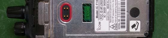
Click to zoom
Application Details
- Equipment Class
- TNF - Licensed Non-Broadcast Transmitter Held to Face
- Date of Grant
- Jun 01, 2014
- Application Purpose
- Original Equipment
- Date of Application
- Jun 01, 2014
- Equipment Note
- VHF Transceivers
- Frequency Range
- 136.00000000 - 174.00000000
- Company
- ICOM Incorporated
- Country
- Japan
Documents & Files
Document Text
Text extracted from the exhibit documents filed with the FCC. Open a document above to read the original.
Users Manual
OPERATING GUIDE The photo shows the UHF transceivers. ▲ Non-display type▲ Simple type▲ 10-key type iF1000 Series VHF TRANSCEIVERS iF2000 Series UHF TRANSCEIVERS i We appreciate you choosing Icom for your communication needs. The MDC 1200 signaling system is built into your IC-F1000/ IC-F2000 series transceiver. READ ALL INSTRUCTIONS carefully and completely before using the transceiver. SAVE THIS OPERATING GUIDE — This operating guide contains important oper ating instructions for: • IC-F1000, IC-F1000S, and IC-F1000T VHF TRANSCEIVERS • IC-F2000, IC-F2000S, and IC-F2000T UHF TRANSCEIVERS Icom, Icom Inc. and the Icom logo are registered trademarks of Icom Incor- porated (Japan) in Japan, the United States, the United Kingdom, Germany, France, Spain, Russia and/or other countries. All other products or brands are registered trademarks or trademarks of their respective holders. IMPORTANT TABLE OF CONTENTS ii IMPORTANT ..........................................................................i TABLE OF CONTENTS ........................................................ii 1 PANEL DESCRIPTION ................................................1–9 ■ Front, top and side panels ............................................1 ■ Function display ...........................................................3 ■ LED indicator ................................................................4 ■ Programmable function keys ........................................5 2 BASIC OPERATION ................................................10–19 ■ Selecting a channel ....................................................10 ■ Receiving and transmitting .........................................10 ■ Emergency Call ..........................................................12 ■ Lone Worker Emergency Call .....................................13 ■ Man Down Emergency Call ........................................13 ■ Motion Detection Emergency Call ..............................13 ■ User set mode ............................................................14 ■ Setting the Beep function ...........................................16 ■ Setting the Beep level ................................................17 ■ Setting the Ringer level ..............................................18 ■ Setting the microphone gain ......................................19 ■ Setting the squelch level ............................................19 3 MDC 1200 SYSTEM OPERATION ..........................20–22 ■ MDC 1200 system operation ......................................20 ■ Receiving a call ..........................................................20 ■ Transmitting a call .......................................................22 ■ Front, top and side panels * Names for the non-display type transceiver There are three types of transceivers in the IC-F1000 and IC-F2000 series. IC-F1000/F2000: Non-display type IC-F1000S/F2000S: Simple type [display + 4 keys (P0–P3)] IC-F1000T/F2000T: 10-key type [display + 4 keys + 10-key pad] The illustration is for the 10-key type. Your transceiver may have a FUNCTION DISPLAY, [P0]– [P3], or 10-KEY PAD, depending on the transceiver version. q ROTARY SELECTOR Rotate to select the preset memory channels. ➥ w VOLUME CONTROL [VOL] Rotate to turn the power ON or OFF and to adjust the ➥ audio level. e DEALER-ASSIGNABLE KEY [Emer] A desired function can be programmed by your dealer. ➥ 1 1 PANEL DESCRIPTION w VOLUME CONTROL [VOL] e [Emer] Speaker r SPEAKER- MICROPHONE JACK Microphone t FUNCTION D I S PL AY y [P0], [P1], [P2], [P3] 10-KEY PAD i PTT SWITCH [PTT] o LED INDICATOR !0 ANTENNA CONNECTOR u [UP]/ [Upper]* u [DOWN]/ [Lower]* q ROTARY SELECTOR 2 1 PANEL DESCRIPTION 1 2 3 4 5 6 7 8 9 10 11 12 13 14 15 16 r SPEAKER-MICROPHONE JACK Connect optional equipment. ➥ NOTE: After turning OFF the transceiver, connect or dis- connect the optional equipment. t FUNCTION DISPLAY Displays a variety of information such as the operating ➥ channel number, channel name, User Set mode con- tents, and so on. See page 3 for details. y DEALER-ASSIGNABLE KEYS [P0] – [P3] Desired functions can be independently programmed ➥ by your dealer. u DEALER-ASSIGNABLE KEYS [UP] or [Upper]*, [DOWN] or [Lower]* Desired functions can be independently programmed ➥ by your dealer. * Names for the non-display type transceivers i PTT SWITCH [PTT] Hold down to transmit, release to receive. ➥ o LED INDICATOR Lights red while transmitting. ➥ Lights green while receiving a signal, or when the ➥ squelch is open. Lights or blinks orange when the matched 2-Tone or ➥ 5-Tone is received, depending on the presetting. You should charge the battery when the indicator slow- ➥ ly blinks. You must charge the battery when the indicator blinks ➥ fast. !0 ANTENNA CONNECTOR Connects the supplied antenna. ➥ Jack cover NOTE: Attach the jack cover when optional equipment is not used. 3 1 PANEL DESCRIPTION ■ Function display q SIGNAL STRENGTH INDICATOR ➥Displays the relative receive signal strength level. w LOW POWER ICON ➥Appears when low output power is selected. • When the battery charge decreases to a set level, low power is automatically selected. e AUDIBLE ICON Appears when the channel is in the ‘audible’ (unmuted) ➥ mode. Appears when a matched 2-Tone or 5-Tone is re- ➥ ceived. r COMPANDER ICON ➥Appears when the Compander function is ON. t SCRAMBLER ICON Appears when the Voice Scrambler function is ON. ➥ y BELL ICON Appears or blinks when a matched 2-Tone or 5-Tone is ➥ received, depending on the presetting. u SCAN ICON Appears or blinks while scanning. ➥ i KEY LOCK ICON Appears when the Key Lock function is ON. ➥ o BATTERY INDICATOR ➥ Displays the remaining battery charge. Blinks when the battery charge decreases to a set ➥ level. ! 0 ALPHANUMERIC READOUT Displays messages such as channel text. ➥ yqiutrew o !0 4 1 1 PANEL DESCRIPTION 16 15 14 13 12 11 10 9 8 7 6 4 5 3 2 ■ LED indicator The LED indicator indicates the status of various parameters of the transceiver as follows: (Referen…
Text truncated - open the document above for the full version.
Users Manual
WORDDEFINITION RDANGER!Personal death, serious injury or an explosion may occur. RWARNING !Personal injury, fire hazard or electric shock may occur. CAUTIONEquipment damage may occur. NOTEIf disregarded, inconvenience only. No risk of personal injury, fire or electric shock. Thank you for choosing the IC-F1000 series v h f t r a n s c e i v e r s or IC-F2000 series u h f t r a n s c e i v- e r s. READ ALL PRECAUTIONS carefully and complete- ly before using the transceiver. 1-1-32 Kamiminami, Hirano-ku, Osaka 547-0003, Japan A-7122H-1EX-q Printed in Japan © 2014 Icom Inc. EXPLICIT DEFINITIONS PRECAUTIONS VHF TRANSCEIVERS Iç-F2000 series UHF TRANSCEIVERS Iç-F1000 series Battery caution• R DANGER! NEVER short terminals (or charging termi- nals) of the battery pack. Also, current may flow into nearby metal objects such as a necklace, so be careful when plac- ing battery packs (or the radio) in handbags, etc. Simply carrying with or placing near metal objects such as a necklace, etc. may cause shorting. This may damage not only the battery pack, but also the radio. R DANGER! DO NOT hammer or otherwise impact the bat- tery. Do not use the battery if it has been severely impact- ed or dropped, or if the battery has been subjected to heavy pressure. Battery damage may not be visible on the outside of the case. Even if the surface of the battery does not show cracks or any other damage, the cells inside the battery may rupture or catch fire. R DANGER! NEVER use or leave battery pack in areas with temperatures above +60°C (+140°F). High tempera- ture buildup in the battery, such as could occur near fires or stoves, inside a sun heated car, or in direct sunlight may cause the battery to rupture or catch fire. Excessive tem- peratures may also degrade battery performance or short- en battery life. R DANGER! DO NOT expose the battery to rain, snow, seawater, or any other liquids. Do not charge or use a wet battery. If the battery gets wet, be sure to wipe it dry before using. R DANGER! KEEP battery packs away from fire. Fire or heat may cause them to rupture or explode. Dispose of used battery packs in accordance with local regulations. R DANGER! NEVER solder the battery terminals, or NEV- ER modify the battery pack. This may cause heat genera- tion, and the battery may burst, emit smoke or catch fire. R DANGER! Use the battery only with the radio for which it is specified. Never use a battery with any other equipment, or for any purpose that is not specified in this instruction manual. R DANGER! If fluid from inside the battery gets in your eyes, blindness can result. Rinse your eyes with clean wa- ter, without rubbing them, and see a doctor immediately. R WARNING! Immediately stop using the battery if it emits an abnormal odor, heats up, or is discolored or deformed. If any of these conditions occur, contact your Icom dealer or distributor. R WARNING! Immediately wash, using clean water, any part of the body that comes into contact with fluid from in- side the battery. R WARNING! NEVER put the battery in a microwave oven, high-pressure container, or in an induction heating cooker. This could cause a fire, overheating, or cause the battery to rupture. CAUTION: Always use the battery within the specified temperature range, for the radio –25°C to +55°C (–13°F to +131° F): ETS version, –30°C to +60°C (–22°F to +140°F): TIA version, and the battery itself –20°C to +60°C (–4°F to +140°F). Using the battery out of its specified temperature range will reduce the battery’s performance and battery life. Please note that the specified temperature range of the bat- tery may exceed that of the radio. In such cases, the radio may not work properly because it is out of its operating tem- perature range. CAUTION: Shorter battery life could occur if the battery is left fully charged, completely discharged, or in an excessive temperature environment (above +50°C; +122°F) for an ex- tended period of time. If the battery must be left unused for a long time, it must be detached from the radio after discharg- ing. You may use the battery until the remaining capacity is about half, then keep it safely in a cool dry place at the fol- lowing temperature range: –20°C (–4°F) to +50°C (+122°F) (within a month) –20°C (–4°F) to +40°C (+104°F) (within three months) –20°C (–4°F) to +20°C (+68°F) (within a year) BE SURE to replace the battery with a new one after five years, even if still holds a charge. The inside battery material will deteriorate after a period of time, even with little use. Charging caution• R DANGER! NEVER charge the battery pack in areas with extremely high temperatures, such as near fires or stoves, inside a sun-heated vehicle, or in direct sunlight. In such en- vironments, the safety/protection circuit in the battery will activate, causing the battery to stop charging. R WARNING! NEVER charge or leave the battery in the battery charger beyond the specified time for charging. If the battery is not completely charged by the specified time, stop charging and remove the battery from the battery char- ger. Continuing to charge the battery beyond the specified time limit may cause a fire, overheating, or the battery may rupture. R WARNING! NEVER insert the radio (battery attached to the radio) into the charger if it is wet or soiled. This could cor- rode the battery charger terminals or damage the charger. The charger is not waterproof. NOTE: Charge the battery within the specified temperature range of +10°C to +40°C (+50°F to +104°F). Otherwise, the charging time will be longer, but the battery will not reach a full charge. While charging, at a point after the temperature goes out of the specified range, the charging will automati- cally stop. PRECAUTIONS (Continued) Misuse of Li-ion batteries may result in the following haz- ards: smoke, fire, or the battery may rupture. Misuse can also cause damage to the battery or degradation of bat- tery performance. PRECAUTIONS R DANGER! NEVER short the terminals of the ba…
Text truncated - open the document above for the full version.
Users Manual
Thank you for purchasing the FA-SC61VC VHFANTENNA. Please read these instructions thoroughly before using the FA-SC61VC. 0 145 MHz 150 MHz 155 MHz 160 MHz 165 MHz 170 MHz 175 MHz 140 MHz 136 MHz Antenna cap FA-SC61VC The optimum bandwidth is ±3% of the tuned frequency. For optimum performance tune to the center transmit frequency of the radio. Cutting Instructions qAlign the bottom of the anten- na onto the 0 position of the cutting guide diagram at left. wMark the antenna at the length corresponding to the desired frequency to be tuned. FA-SC61VC A-6532K-1EX-wPrinted in Japan eCut the antenna to the marked length. • Use a wire cutter that can cut at least 1.2 mm (d) of piano wire. rApply adhesiveto the top of the antenna and attach the supplied antenna cap. • Use of Cemedine Co. Super-X No. 8008 black (Icom parts number: 8950002910) or similar is recommended. T h e a n t e n n a c a n b e u s e d a t i t s o r iginal length for this frequency. No tuning (cutting) is necessary. * ©2006-2009 Icom Inc. Antenna Cutting Chart Center frequency (MHz) Length (mm) 174* 169 163 157 151 146 141 137 133 136 140 145 150 155 160 165 170 175 NOTE: A n t e n n a c a p m u s t b e i n s e r t e d a f t e r c u t t i n g t h e e l e m e n t o t h e r w i s e wa t e r immersion makes the element damaged. CAUTION: Making antenna cuts at other than the prescribed lengths specified could void the user's author ity to operate the equipment.
Cover Letter(s)
May 12, 2014 Ultratech Engineering Labs, Inc. 3000 Bristol Circle Oakville, Ontario L6H 6G4 Subject: Equipment Certification under FCC 47 CFR, Parts 2, 22, 74, 80 and 90 (Subpart I) - Non-Broadcast Radio Transceivers Operating in the Frequency Band 136-174 MHz (25 kHz and 12.5 kHz Channel Spacing) Applicant: ICOM Incorporated Product: VHF Transceiver Model: IC-F1000/F1000S/F1000T FCC ID: AFJ362000 Dear Sir/Madam: As appointed agent for ICOM Incorporated, we would like to submit the application to you for FCC certification of the above product. Please review all files uploaded to your electronic filing site. Note 1: As declared by the applicant in the attestation letter submitted with this filing, 25kHz channel spacing (16K0F3E) operation of this radio is permanently disabled for Part 90 use as required by FCC mandate. Test performed for 25kHz channel spacing are for parts 22, 74 & 80 certifications only. Note 2: ICOM hereby request FCC to list the entire frequency range from 136-174 MHz under FCC rules as per the reasons explained in the attached Frequency Justification letter submitted with this filing. If you have any queries, please do not hesitate to contact us. Yours truly, Dharmajit Solanki Dharmajit Solanki Authorized Agent UltraTech Group of Labs FCC TCB & IC CB Ultratech’s Accreditations: 0685 91038 1309 46390-2049 NVLAP LAB CODE 200093-0 SL2-IN-E-1119R Korea KCC-RRA CA2049 TL363_B TPTDP DA1300 3000 Bristol Circle, Oakville, Ontario, Canada L6H 6G4 Tel.: (905) 829-1570 Fax.: (905) 829-8050 Website: www.ultratech-labs.com Email: [email protected]
External Photos
-- Picture -- -- IC-F1000 Series -- 1 / 3 Outside – Front - IC-F1000 IC-F1000T IC-F1000S Outside – Back - IC-F1000/IC-F1000S/IC-1000T Without Battery Pack -- Picture -- -- IC-F1000 Series -- 2 / 3 Outside IC-F1000/IC-F1000S/IC-1000T – Top – IC-F1000/IC-F1000S/IC-1000T – Left – IC-F1000/IC-F1000S/IC-1000T – Bottom – IC-F1000/IC-F1000S/IC-1000T – Right –
ID Label/Location Info
-- Serial Plate -- -- IC-F1000 Series -- 1 / 3 -- Serial Plate -- -- IC-F1000 Series -- 2 / 3 -- Serial Plate -- -- IC-F1000 Series -- 3 / 3
Internal Photos
-- Picture -- -- IC-F1000 Series -- 3 / 3 Main Board – Front - Main Board – Back - IC-F1000 IC-F1000T – Front - IC-F1000S – Front - IC-F1000/IC-F1000S/IC-F1000T ANT Board – Front - ANT Board – Back - IC-F1000/IC-F1000S/IC-F1000T IC-F1000/IC-F1000S/IC-F1000T
RF Exposure Info
SAFETY TRAINING INFORMATION FCC INFORMATION • FOR CLASS A UNINTENTIONAL RADIATORS: This equipment has been tested and found to comply with the limits for a Class A digital device, pursuant to part 15 of the FCC Rules. These limits are designed to provide reasonable protection against harmful interfer- ence when the equipment is operated in a commercial environment. This equipment generates, uses, and can radiate radio frequency energy and, if not installed and used in accordance with the instruction manual, may cause harmful interference to radio communica- tions. Operation of this equipment in a residential area is likely to cause harmful interference in which case the user will be required to correct the interference at his own expense. This device complies with Part 15 of the FCC Rules. Operation is subject to the condition that this device does not cause harmful interference. CAUTION: Changes or modifications to this transceiver, not ex- pressly approved by Icom Inc., could void your au- thority to operate this transceiver under FCC regu- lations. ISO 3166-1 CountryCodesCountryCodes 1 2 3 4 5 6 7 8 9 10 11 12 13 14 15 16 17 Austria Belgium Bulgaria Croatia Czech Republic Cyprus Denmark Estonia Finland France Germany Greece Hungary Iceland Ireland Italy Latvia AT BE BG HR CZ CY DK EE FI FR DE GR HU IS IE IT LV 18 19 20 21 22 23 24 25 26 27 28 29 30 31 32 33 Liechtenstein Lithuania Luxembourg Malta Netherlands Norway Poland Portugal Romania Slovakia Slovenia Spain Sweden Switzerland Turkey United Kingdom LI LT LU MT NL NO PL PT RO SK SI ES SE CH TR GB COUNTRY CODE LIST < Intended Country of Use > AT FI IT PL GB RO BE FR LV PT IS TR CY DE LT SK LI HR CZ GR LU SI NO DK HU MT ES CH EE IE NL SE BG WARNING Your Icom radio generates RF electromagnetic energy during transmit mode. This radio is de- signed for and classified as “Occupational Use Only”, meaning it must be used only during the course of employment by individuals aware of the hazards, and the ways to minimize such haz- ards. This radio is NOT intended for use by the “General Population” in an uncontrolled environ- ment. This radio has been tested and complies with the FCC and IC RF exposure limits for “Oc- cupational Use Only”. In addition, your Icom radio complies with the following Standards and Guidelines with regard to RF energy and electromagnetic energy levels and evaluation of such levels for exposure to humans: FCC OET Bulletin 65 Edition 97-01 Supplement C, Evaluating Compliance with FCC Guidelines for Human Ex-• posure to Radio Frequency Electromagnetic Fields. American National Standards Institute (C95.1-1992), IEEE Standard for Safety Levels with Respect to Human • Exposure to Radio Frequency Electromagnetic Fields, 3 kHz to 300 GHz. American National Standards Institute (C95.3-1992), IEEE Recommended Practice for the Measurement of Po-• tentially Hazardous Electromagnetic Fields– RF and Microwave. The antennas, batteries, belt clips, speaker-microphone, and other accessories that are listed in “OPTIONS” of • the INSTRUCTIONS sheet, are authorized for use with this product. Use of accessories other than those spec- ified may result in RF exposure levels exceeding the FCC and IC requirements for wireless RF exposure. CAUTION To ensure that your expose to RF electromagnetic energy is within the FCC and IC al- lowable limits for occupational use, always adhere to the following guidelines: DO NOT • operate the radio without a proper antenna attached, as this may damaged the radio and may also cause you to exceed FCC and IC RF exposure limits. A proper antenna is the antenna supplied with this radio by the manufacturer or antenna specifically authorized by the manufacturer for use with this radio. DO NOT• transmit for more than 50% of total radio use time (“50% duty cycle”). Transmitting more than 50% of the time can cause FCC and IC RF exposure compliance requirements to be exceeded. The radio is transmit- ting when the LED indicator lights red. You can cause the radio to transmit by pressing the “PTT” switch. • ALWAYS keep the antenna at least 2.5 cm (1 inch) away from the body when transmitting and only use the Icom belt-clips listed in “OPTIONS” of the INSTRUCTIONS sheet when attaching the radio to your belt, etc., to ensure FCC and IC RF exposure compliance requirements are not exceeded. To provide the recipients of your transmission the best sound quality, hold the antenna at least 5 cm (2 inches) from your mouth, and slightly off to one side. The information listed above provides the user with the information needed to make him or her aware of RF expo- sure, and what to do to assure that this radio operates with the FCC and IC RF exposure limits of this radio. Electromagnetic Interference/Compatibility During transmissions, your Icom radio generates RF energy that can possibly cause interference with other devic- es or systems. To avoid such interference, turn off the radio in areas where signs are posted to do so. DO NOT op- erate the transmitter in areas that are sensitive to electromagnetic radiation such as hospitals, aircraft, and blast- ing sites. Occupational/Controlled Use The radio transmitter is used in situations in which persons are exposed as consequence of their employment pro- vided those persons are fully aware of the potential for exposure and can exercise control over their exposure. SAFETY TRAINING INFORMATION ( Continued ) Icom, Icom Inc. and the Icom logo are registered trade- marks of Icom Incorporated (Japan) in Japan, the Unit- ed States, the United Kingdom, Germany, France, Spain, Russia and/or other countries. All other products or brands are registered trademarks or trademarks of their respective holders. CLEAN THE TRANSCEIVER THOROUGHLY WITH FRESH WATER after exposure to saltwater, and dry it before operating. Otherwise, the transceiver's keys, switches and controllers may become unusable due to salt crystallization. NOTE: DO NOT submerge the transceiver in water if there is any reason (o…
Text truncated - open the document above for the full version.
Test Report
VHF Transceiver Model No.: IC-F1000/F1000S/F1000T FCC ID: AFJ362000 Applicant: ICOM Incorporated 1-1-32, Kamiminami, Hirano-ku Osaka, Japan, 547-0003 Tested in Accordance With Federal Communications Commission (FCC) 47 CFR, Parts 2, 22, 74, 80 and 90 (Subpart I) UltraTech's File No.: ICOM-361Q_FCC90 This Test report is Issued under the Authority of Tri M. Luu, Professional Engineer, Vice President of Engineering UltraTech Group of Labs Date: May 12, 2014 Report Prepared by: Dharmajit Solanki Issued Date: May 12, 2014 Tested by: Wei Wu Test Dates: April 08-23, 2014 The results in this Test Report apply only to the sample(s) tested, and the sample tested is randomly selected. This report must not be used by the client to claim product endorsement by NVLAP or any agency of the US Government. UltraTech 3000 Bristol Circle, Oakville, Ontario, Canada, L6H 6G4 Tel.: (905) 829-1570 Fax.: (905) 829-8050 Website: www.ultratech-labs.com , Email: [email protected], Email: [email protected] Korea KCC-RRA 91038 1309 46390-2049 NVLAP LAB CODE 200093-0 SL2-IN-E- 1119R CA2049 TL363_B TPTDP DA1300 FCC Parts 2, 22, 74, 80 and 90 Subpart I, Non-Broadcast Radio Transceivers Contents i VHF Transceiver, Model IC-F1000/F1000S/F1000T FCC ID: AFJ362000 ULTRATECH GROUP OF LABS File #: ICOM-361Q_FCC90 3000 Bristol Circle, Oakville, Ontario, Canada L6H 6G4 May 12, 2014 Tel. #: 905-829-1570, Fax. #: 905-829-8050, Email: [email protected] , Website: http://www.ultratech-labs.com All test results contained in this engineering test report are traceable to National Institute of Standards and Technology (NIST) TABLE OF CONTENTS EXHIBIT 1. INTRODUCTION ............................................................................................................................................ 1 1.1. SCOPE............................................................................................................................................................................ 1 1.2. RELATED SUBMITTAL(S)/GRANT(S) ...................................................................................................................... 1 1.3. NORMATIVE REFERENCES ...................................................................................................................................... 1 EXHIBIT 2. PERFORMANCE ASSESSMENT.................................................................................................................. 2 2.1. CLIENT INFORMATION ............................................................................................................................................. 2 2.2. EQUIPMENT UNDER TEST (EUT) INFORMATION ................................................................................................ 2 2.3. EUT’S TECHNICAL SPECIFICATIONS ..................................................................................................................... 3 2.4. LIST OF EUT’S PORTS ................................................................................................................................................ 3 2.5. ANCILLARY EQUIPMENT ......................................................................................................................................... 4 2.6. GENERAL TEST SETUP .............................................................................................................................................. 4 EXHIBIT 3. EUT OPERATING CONDITIONS AND CONFIGURATIONS DURING TESTS................................... 5 3.1. CLIMATE TEST CONDITIONS................................................................................................................................... 5 3.2. OPERATIONAL TEST CONDITIONS & ARRANGEMENT FOR TEST SIGNALS ................................................ 5 EXHIBIT 4. SUMMARY OF TEST RESULTS .................................................................................................................. 6 4.1. LOCATION OF TESTS ................................................................................................................................................. 6 4.2. APPLICABILITY & SUMMARY OF EMISSION TEST RESULTS........................................................................... 6 4.3. MODIFICATIONS INCORPORATED IN THE EUT FOR COMPLIANCE PURPOSES .......................................... 6 EXHIBIT 5. MEASUREMENTS, EXAMINATIONS & TEST DATA FOR EMC EMISSIONS .................................. 7 5.1. TEST PROCEDURES .................................................................................................................................................... 7 5.2. MEASUREMENT UNCERTAINTIES.......................................................................................................................... 7 5.3. MEASUREMENT EQUIPMENT USED....................................................................................................................... 7 5.4. ESSENTIAL/PRIMARY FUNCTIONS AS DECLARED BY THE MANUFACTURER ........................................... 7 5.5. RF POWER OUTPUT [§§ 2.1046, 22.565, 74.461, 80.215 & 90.205].......................................................................... 8 5.6. AUDIO FREQUENCY RESPONSE [§ 2.1047(A), 80.213(E) & 90.242(B)(8)]........................................................... 9 5.7. MODULATION LIMITING [§§ 2.1047 (B), 74.463, 80.213 & 90.210]..................................................................... 14 5.8. OCCUPIED BANDWIDTH & EMISSION MASK [§§ 2.1049, 74.462, 80.211(F), 90.209 & 90.210]...................... 19 5.9. TRANSMITTER ANTENNA POWER SPURIOUS/HARMONIC CONDUCTED EMISSIONS [§§ 2.1051, 2.1057, 22.359, 80.211(F)(3) & 90.210].................................................................................................................................... 39 5.10. TRANSMITTER SPURIOUS/HARMONIC RADIATED EMISSIONS [§§ 2.1053, 2.1057, 22.359, 80.211(F)(3) & 90.210] .....................................…
Text truncated - open the document above for the full version.
Test Setup Photos
ANNEX 1 - TEST SETUP PHOTOGRAPHS ICOM Incorporated VHF Transceiver, M/N: IC-F1000/F1000S/F1000T FCC ID: AFJ362000, IC: 202D-362000 Plot #1: Tx Radiated Emission Test Setup ANNEX 1 - TEST SETUP PHOTOGRAPHS ICOM Incorporated VHF Transceiver, M/N: IC-F1000/F1000S/F1000T FCC ID: AFJ362000, IC: 202D-362000 Plot #2: Tx Radiated Emission Test Setup ANNEX 1 - TEST SETUP PHOTOGRAPHS ICOM Incorporated VHF Transceiver, M/N: IC-F1000/F1000S/F1000T FCC ID: AFJ362000, IC: 202D-362000 Plot #3: Tx Radiated Emission Test Setup ANNEX 1 - TEST SETUP PHOTOGRAPHS ICOM Incorporated VHF Transceiver, M/N: IC-F1000/F1000S/F1000T FCC ID: AFJ362000, IC: 202D-362000 Plot #4: Tx Radiated Emission Test Setup
Contact Information
Applicant
Tatsuo Yano(General Manager of QA Department)
Test Firm
UltraTech Engineering Labs Inc.Tri Luu
Technical Specifications
| # | Rule Parts | Frequency Range | Power Output | Emission | Tolerance |
|---|---|---|---|---|---|
| 4 | 22,74,8 | 136 MHz - 174 MHz | 1 W | 16K0F3E | 2.5 ppm |
Other Applications from ICOM Incorporated

AFJ453700
Jul 23, 2026Mobile Transceiver
Equipment Class
DTS - Digital Transmission System
AFJ452000
Jun 02, 2026VHF DIGITAL TRANSCEIVER
Equipment Class
TNF - Licensed Non-Broadcast Transmitter Held to Face
AFJ452100
May 12, 2026UHF DIGITAL TRANSCEIVER
Equipment Class
TNF - Licensed Non-Broadcast Transmitter Held to Face
AFJ444500
Sep 12, 2024Scanning Receiver
Equipment Class
CSR - Scanning Receiver
AFJ410900
Jul 09, 2024Linear Amplifier
Equipment Class
AMP - Amplifier