AFJ365900VHF Digital Transceiver
ICOM Incorporated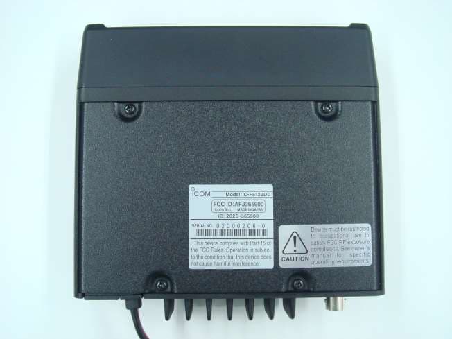
Click to zoom
Application Details
- Equipment Class
- TNB - Licensed Non-Broadcast Station Transmitter
- Date of Grant
- Mar 17, 2015
- Application Purpose
- Original Equipment
- Date of Application
- Mar 17, 2015
- Equipment Note
- VHF Digital Transceiver
- Frequency Range
- 136.00000000 - 174.00000000
- Company
- ICOM Incorporated
- Country
- Japan
Documents & Files
Document Text
Text extracted from the exhibit documents filed with the FCC. Open a document above to read the original.
Users Manual
Thank you for choosing the IC-F5122DD v h f d i g i- t a l t r a n s c e i v e r or IC-F6122DD u h f d i g i t a l t r a n s- c e i v e r. Read this maintenance note for periodic transceiver checks and simple maintenance. MAINTENANCE NOTE VHF DIGITAL TRANSCEIVER Iç-F6122DD UHF DIGITAL TRANSCEIVER Iç-F5122DD ABOUT THE STATUS INDICATOR The Status Indicator indicates various transceiver status. Status Indicator ColorStatusDescription GreenLitPower ON and standing by BlinkReceiving data RedLitTransmitting data OrangeBlinksA problem occurred. The cause may differ, depending on the blinking pattern. See the diagram below for details about the blinking patterns and causes. When activating the final amplifier protection• OOOO 500 ms* PLL unlock• OOOOOO 500 ms* Overvoltage• OOOOOO 500 ms* Low voltage• OOOOOOOO 500 ms* *Approximately (ms: millisecond) O=Orange If the Status Indicator blinks orange, contact your dealer or system integrator. FUSE REPLACEMENT A fuse is installed in the supplied DC power cable. If a fuse blows, track down the source of the problem, repair it, and then replace the damaged fuse with a new rated one. ❏ Fuse rating: 10 A USE only a 10 A fuse. CLEANING If the transceiver becomes dusty or dirty, wipe it clean with a soft, dry cloth. DO NOT use harsh solvents such as benzene or alcohol, as they may damage the transceiver sur- faces. ABOUT ETHERNET PORT INDICATORS The Ethernet port indicators indicate the status of the net- work and data. * The Ethernet port may not be installed, depending on the transceiv- er version. SPEED LINK/ACT ColorStatusDescription SPEEDOrange Not litConnected to 10BASE-T LitConnected to 100BASE-TX LINK/ ACT Green Not litNot connected to the network LitConnected to the network BlinksReceiving and Transmitting data Icom, Icom Inc. and the Icom logo are registered trademarks of Icom Incor- porated (Japan) in Japan, the United States, the United Kingdom, Germany, France, Spain, Russia, and/or other countries. A-7202H-2EX Printed in Japan © 2015 Icom Inc. 1-1-32 Kamiminami, Hirano-ku, Osaka 547-0003, Japan
Users Manual
- 4 - - 1 - Thank you for choosing the IC-F5122DD v h f digital t r a n s- c e i v e r or IC-F6122DD u h f digital t r a n s c e i v e r. READ ALL PRECAUTIONS carefully and completely be- fore using your transceiver. 1-1-32 Kamiminami, Hirano-ku, Osaka 547-0003, Japan A-7202H-1EX Printed in Japan © 2015 Icom Inc. PRECAUTIONS VHF DIGITAL TRANSCEIVER Iç-F6122DD UHF DIGITAL TRANSCEIVER Iç-F5122DD FCC INFORMATION • FOR CLASS A UNINTENTIONAL RADIATORS: This equipment has been tested and found to comply with the limits for a Class A digital device, pursuant to part 15 of the FCC Rules. These limits are designed to provide rea- sonable protection against harmful interference when the equipment is operated in a commercial environment. This equipment generates, uses, and can radiate radio frequen- cy energy and, if not installed and used in accordance with the instruction manual, may cause harmful interference to radio communications. Operation of this equipment in a res- idential area is likely to cause harmful interference in which case the user will be required to correct the interference at his own expense. This device complies with Part 15 of the FCC Rules. Opera- tion is subject to the condition that this device does not cause harmful interference. INFORMATIONS FCC • POUR LES RAYONNEMENTS NON INTENTIONNELS DE CLASSE A: Cet équipement a été testé et reconnu conforme aux limi- tes fixées pour un appareil numérique de classe A, confor- mément au point 15 de la réglementation FCC. Ces limites assurent une protection raisonnable contre les interférences nuisibles lorsque l'équipement est utilisé dans un environne- ment commercial. Cet équipement génère une énergie de radio fréquence, utilise et rayonner et s'il n'est pas installé et utilisé conformément au manuel d'instruction, peut cau- ser des interférences nuisibles aux communications radio. Le fonctionnement de cet équipement dans une zone rési- dentielle est susceptible de causer des interférences nuisi- bles lorsque l'utilisateur doit corriger les interférences à ses propres frais. Cet appareil respecte les conditions établies au paragraphe 15 des règles de la FCC. Son utilisation est assujettie à la condition de ne pas provoquer des interférences nuisibles. Icom, Icom Inc. and the Icom logo are registered trademarks of Icom Incor- porated (Japan) in Japan, the United States, the United Kingdom, Germany, France, Spain, Russia and/or other countries. PRECAUTIONS RWARNING! NEVER connect the radio to an AC outlet. This may pose a fire hazard or result in an electric shock. RWARNING! NEVER connect the radio to a power source of more than 16 V DC such as a 24 V battery. This could damage the radio. RWARNING! NEVER cut the DC power cable between the DC plug and fuse holder. If an incorrect connection is made after cutting, the radio might be damaged. RWARNING! NEVER place the radio where normal operation of the vehicle may be hindered or where it could cause bodily injury. CAUTION: NEVER expose the radio to rain, snow or any liquids. DO NOT operate or place the radio in areas with temper- atures below –30°C (–22°F) or above +60°C (+140°F), or in areas subject to direct sunlight, such as the dashboard. DO NOT operate the radio without running the vehicle’s engine. The vehicle’s battery will quickly run out when the ra- dio transmits while the vehicle’s engine is OFF. DO NOT place the radio in excessively dusty environ- ments. DO NOT place the radio against walls. Otherwise heat dis- sipation will be obstructed. DO NOT use harsh solvents such as benzine or alcohol when cleaning, as they damage the radio surfaces. BE CAREFUL! The radio will become hot when operating continuously for long periods. Place the radio in a secure place to avoid inadvertent use by children. PRÉCAUTIONS R AVERTISSEMENT! NE JAMAIS connecter l'émetteur-récepteur a une alimentation CA au risque de pro- voquer un incendie ou un choc electrique. RAVERTISSEMENT! NE JAMAIS brancher l’émet- teur-récepteur sur une source d’alimentation de plus de 16 V CC. NE JAMAIS émettre lorsque le coupleur est activé (ON), alors qu'aucune antenne n'est raccordée, au risque d'en- dommager gravement l'émetteur-récepteur. RAVERTISSEMENT! NE JAMAIS couper le câble d’alimentation CC entre la prise CC à l’arrière de l’émetteur- récepteur et le porte fusible. L’émetteur-récepteur peut être endommagé par la suite en cas de connexion inappropriée. MISE EN GARDE: NE JAMAIS placer l’émetteur-ré- cepteur à un emplacement où il pourrait gêner le fonction- nement normal du navire ou provoquer des blessures cor- porelles. MISE EN GARDE: NE JAMAIS exposer l’émetteur- récepteur à la pluie, à la neige ou à tout autre liquide. NE PAS utiliser ou placer l’émetteur-récepteur dans des zones où la temperature est inférieure à –30°C (–22°F) ou supérieure à +60°C (+140°F), ou dans des zones soumises au rayonnement solaire direct, telles le tableau de bord. En utilisation mobile, NE PAS utiliser un emetteur-recep- teur embarque avec le moteur du vehicule arrete. La batterie du véhicule sera rapidement épuisé lorsque la radio trans- met lorsque le moteur du véhicule est éteint. NE PAS placer l'émetteur-récepteur dans un environne- ment excessivement poussiereux ou en plein soleil. NE PAS placer l'émetteur-récepteur contre un mur pour ne pas gêner la dispersion de la chaleur. NE PAS utiliser de solvants agressifs tels que l'essence ou l'alcool pour nettoyer le l’émetteur-récepteur, en raison des risques d'endommager la surface du l’émetteur-récepteur. ATTENTION! L’émetteur-récepteur chauffe en cas d’utili- sation continue sur une longue durée. Placer l’émetteur-récepteur hors de portée des enfants pour éviter toute utilisation inopinée. EXPLICIT DEFINITIONS WORD DEFINITION RWARNING! Personal injury, fire hazard or electric shock may occur. CAUTIONEquipment damage may occur. NOTE If disregarded, inconvenience only. No risk of personal injury, fire or electric shock. DÉFINITIONS EXPLICITES TERME DÉFINITION RAVERTISSE- MENT! …
Text truncated - open the document above for the full version.
Cover Letter(s)
Ult G FC Ultrate Accre NVLAP SL Ko T 3 Te Fa Website Email: traTec Group of Labs CC TCB & IC CB ech’s ditations: 0685 91038 1309 46390-2049 LAB CODE 2000 L2-IN-E-1119R orea KCC-RRA CA2049 TL363_B PTDP DA1300 3000 Bristol Circle, Oakville, Ontario, Canada L6H 6G4 el.: (905) 829-1570 ax.: (905) 829-8050 : www.ultratech-labs. vic@ultratech-labs. c M U 3 O L S A P M F D A y e N u l e I f Y D D A h 093-0 com com March 13, 201 Ultratech Eng 000 Bristol C Oakville, Onta 6H 6G4 Subject: Applicant: Product: Model: FCC ID: Dear Sir/Mada As appointed a ou for FCC ce lectronic filing Note: ICOM he nder FCC rul etter submitte f you have an Yours truly, Dharmajit Solan Dharmajit Sola Authorized Ag 5 gineering Lab ircle rio Equipme n 90 (Subpa the Frequ e Spacing) ICOM Inc o VHF Digita IC-F5122D AFJ365900 am: agent for ICO ertification of g site. ereby reques es as per th e d with this fili y queries, pl e anki anki en t bs, Inc. nt Certificatio rt I) - Non-Br ency Band 1 orporated al Transceive DD 0 OM Incorpora the above pr t FCC to list t e reasons exp ng. ease do not h on under FCC roadcast Rad 36-174 MHz er ated, we woul roduct. Pleas the entire freq plained in the esitate to co n C 47 CFR, Pa dio Transceiv (12.5 kHz an ld like to subm se review all fi quency range attached Fre q ntact us. arts 2, 22, 74 vers Operati d 6.25 kHz C mit the applica iles uploaded from 136-174 quency Justif , 80 and ing in Channel ation to d to your 4 MHz fication
ID Label/Location Info
Serial Plate Layout FCC ID LABEL CAUTION LABEL
Internal Photos
Main Board (side-A) view Main Board (side-B) view Main Board (side-A) view Main Board (side-B) view Front Board (side-A) view (#02 only) Front Board (side-B) view (#02 only) Front Board (side-A) view (#02 only) Front Board (side-B) view (#02 only) Front Board (side-A) view (#12 only) Front Board (side-B) view (#12 only) Front Board (side-A) view (#12 only) Front Board (side-B) view (#12 only)
RF Exposure Info
- 2 -- 3 - WARNING Your Icom radio generates RF electromag- netic energy during transmit mode. This ra- dio is designed for and classified as “Occu- pational Use Only”, meaning it must be used only during the course of employment by in- dividuals aware of the hazards, and the ways to minimize such hazards. This radio is NOT intended for use by the “General Popula- tion” in an uncontrolled environment. • For compliance with FCC and IC RF Exposure Require- ments, the transmitter antenna installation shall comply with the following three conditions: 1. The transmitter antenna gain shall not exceed 0 dBi. 2. IC-F5122DD: The antenna is required to be located outside of a vehicle and kept at a distance of 32 centimeters or more between the transmitting antenna of this device and any persons during operation. For small vehicle as worst case, the an- tenna shall be located on the roof top at any place on the centre line along the vehicle in order to achieve 32 centimeters separation distance. In order to ensure this distance is met, the installation of the antenna must be mounted at least 32 centimeters away from the nearest edge of the vehicle in order to protect against exposure to bystanders. 3. IC-F6122DD: The antenna is required to be located outside of a vehicle and kept at a distance of 28 centimeters or more between the transmitting antenna of this device and any persons during operation. For small vehicle as worst case, the an- tenna shall be located on the roof top at any place on the centre line along the vehicle in order to achieve 28 centimeters separation distance. In order to ensure this distance is met, the installation of the antenna must be mounted at least 28 centimeters away from the nearest edge of the vehicle in order to protect against exposure to bystanders. 4. IC-F5122DD: Transmit only when people outside the vehicle are at least the recommended minimum distance of 71 centime- ters away from the properly installed antenna. This sepa- ration distance will ensure that there is sufficient distance from a properly installed externally-mounted antenna to satisfy the RF exposure requirements in the applicable RF exposure compliance standards. 5. IC-F6122DD: Transmit only when people outside the vehicle are at least the recommended minimum distance of 62 centime- ters away from the properly installed antenna. This sepa- ration distance will ensure that there is sufficient distance from a properly installed externally-mounted antenna to satisfy the RF exposure requirements in the applicable RF exposure compliance standards. CAUTION To ensure that your exposure to RF electro- magnetic energy is within the FCC and IC al- lowable limits for occupational use, always adhere to the following guidelines: • DO NOT operate the radio without a proper antenna at- tached, as this may damage the radio and may also cause you to exceed FCC and IC RF exposure limits. A proper an- tenna is the antenna supplied with this radio by the manu- facturer or an antenna specifically authorized by the manu- facturer for use with this radio. • DO NOT transmit for more than 50% of total radio use time (“50% duty cycle”). Transmitting more than 50% of the time can cause FCC and IC RF exposure compliance require- ments to be exceeded. The radio is transmitting when the LED indicator lights red. Electromagnetic Interference/Compatibility During transmissions, your Icom radio generates RF ener- gy that can possibly cause interference with other devices or systems. To avoid such interference, turn off the radio in ar- eas where signs are posted to do so. DO NOT operate the transmitter in areas that are sensitive to electromagnetic ra- diation such as hospitals, aircraft, and blasting sites. SAFETY TRAINING INFORMATION AVERTISSEMENT Votre radio Icom produit une énergie électromagnétique de radiofréquences (RF), en mode de transmission. Cette ra- dio est conçue pour un «usage profes- sionnel seulement» et classée comme tel, ce qui signifie qu’elle doit être utilisée uniquement dans le cadre d’un travail par des personnes conscientes des dangers et des mesures visant à minimiser ces dangers. Elle N’EST PAS conçue pour une «utilisation grand public», dans un environnement non contrôlé. • Afin de satisfaire aux exigences de la FCC et d’IC en matiè- re d’exposition aux RF, il est nécessaire que l’antenne soit installée conformément aux trois conditions suivantes: 1. Le gain de l’antenne du radio émetteur ne doit pas dé- passer 0dBi. 2. IC-F5122DD: Il faut que l’antenne émettrice de cet appareil soit placée à l’extérieur d’un véhicule et tenue éloignée d’au moins 32 cm de toute personne pendant le fonctionnement. Dans le pire des cas, pour un petit véhicule, l’antenne doit être placée sur le toit, n’importe où dans l’axe central du véhicule, afin de respecter une distance de 32 cm du bord le plus rapproché du véhicule et ainsi éviter que les personnes présentes soient exposées. 3. IC-F6122DD: Il faut que l’antenne émettrice de cet appareil soit placée à l’extérieur d’un véhicule et tenue éloignée d’au moins 28 cm de toute personne pendant le fonctionnement. Dans le pire des cas, pour un petit véhicule, l’antenne doit être placée sur le toit, n’importe où dans l’axe central du véhicule, afin de respecter une distance de 28 cm du bord le plus rapproché du véhicule et ainsi éviter que les personnes présentes soient exposées. 4. IC-F5122DD: Émettre uniquement lorsque les personnes à l’extérieur du véhicule se trouvent à au moins la distance minimale recommandée de 71 cm de l’antenne correctement ins- tallée. Cette distance de sécurité assurera que les per- sonnes soient placées suffisamment loin d’une antenne correctement fixée à l’extérieur pour satisfaire aux exi- gences en matière d’exposition aux RF, en vertu des nor- mes de conformité applicables. 5. IC-F6122DD: Émettre uniquement lorsque les personnes à l’extérieur du véhicule se trouvent à au moins la distance minimale recommandée de 62 cm de l’antenne correctement …
Text truncated - open the document above for the full version.
Test Report
This Te s Tri M. Lu Vice Pre UltraTec Date: M Report P Issued D The res This rep 91038 st report is Iss uu, BASc, esident of Eng ch Group of L arch 13, 2015 Prepared by: Date: March 1 sults in this Test port must not be Web 1309 Federal 47 CFR Ultr sued under th gineering Labs 5 Dharmajit So 13, 2015 Report apply onl used by the clie 30 bsite: www.ultratech 46390-20 VHF Dig Model N FCC ID A ICOM 1-1-32, Kam Osaka, J Tested in l Communic R, Parts 2, 22 raTech's File he Authority o olanki ly to the sample( nt to claim produ Ult 00 Bristol Circle, O Tel.: (905) 829-15 h-labs.com, Email: 049 N V COD gital Transc No.: IC-F51 D: AFJ3659 Applicant: M Incorporat miminami, H Japan, 547- n Accordance cations Com 2, 74, 80 an e No.: 15ICOM of Tested b Test Da (s) tested, and th uct endorsement traTech Oakville, Ontario, Ca 570 Fax.: (90 vic@ultratech-labs VLAP LAB DE 200093-0 ceiver 22DD 900 ted Hirano-ku -0003 e With mmission (F d 90 (Subpa M399_FCC90 by: Wei Wu tes: Feb 10 – he sample tested tby NVLAP or an h anada, L6H 6G4 05) 829-8050 s.com, Email: tri@u SL2-IN-E- 1119R FCC) art I) 0 – March 03, 20 d is randomly sele ny agency of the ultratech-labs.com Korea KCC- RRA CA2049 015 ected. US Governmen t TL363_B T D A t. PTDP A1300 FCC Parts 2, 22, 74, 80 and 90 Subpart I, Non-Broadcast Radio Transceivers Contents i VHF Digital Transceiver, Model IC-F5122DD FCC ID: AFJ365900 ULTRATECH GROUP OF LABS File #: 15ICOM399_FCC90 3000 Bristol Circle, Oakville, Ontario, Canada L6H 6G4 March 13, 2015 Tel. #: 905-829-1570, Fax. #: 905-829-8050, Email: [email protected] , Website: http://www.ultratech-labs.com All test results contained in this engineering test report are traceable to National Institute of Standards and Technology (NIST) TABLE OF CONTENTS EXHIBIT 1. INTRODUCTION ............................................................................................................................................ 1 1.1. SCOPE ............................................................................................................................................................................ 1 1.2. RELATED SUBMITTAL(S)/GRANT(S) ...................................................................................................................... 1 1.3. NORMATIVE REFERENCES ...................................................................................................................................... 1 EXHIBIT 2. PERFORMANCE ASSESSMENT .................................................................................................................. 2 2.1. CLIENT INFORMATION ............................................................................................................................................. 2 2.2. EQUIPMENT UNDER TEST (EUT) INFORMATION ................................................................................................ 2 2.3. EUT’S TECHNICAL SPECIFICATIONS ..................................................................................................................... 3 2.4. LIST OF EUT’S PORTS ................................................................................................................................................ 3 2.5. ANCILLARY EQUIPMENT ......................................................................................................................................... 3 2.6. GENERAL TEST SETUP .............................................................................................................................................. 4 EXHIBIT 3. EUT OPERATING CONDITIONS AND CONFIGURATIONS DURING TESTS ................................... 5 3.1. CLIMATE TEST CONDITIONS ................................................................................................................................... 5 3.2. OPERATIONAL TEST CONDITIONS & ARRANGEMENT FOR TEST SIGNALS ................................................ 5 EXHIBIT 4. SUMMARY OF TEST RESULTS .................................................................................................................. 6 4.1. LOCATION OF TESTS ................................................................................................................................................. 6 4.2. APPLICABILITY & SUMMARY OF EMISSION TEST RESULTS........................................................................... 6 4.3. MODIFICATIONS INCORPORATED IN THE EUT FOR COMPLIANCE PURPOSES .......................................... 6 EXHIBIT 5. MEASUREMENTS, EXAMINATIONS & TEST DATA FOR EMC EMISSIONS .................................. 7 5.1. TEST PROCEDURES .................................................................................................................................................... 7 5.2. MEASUREMENT UNCERTAINTIES .......................................................................................................................... 7 5.3. MEASUREMENT EQUIPMENT USED ....................................................................................................................... 7 5.4. ESSENTIAL/PRIMARY FUNCTIONS AS DECLARED BY THE MANUFACTURER ........................................... 7 5.5. RF POWER OUTPUT [§§ 2.1046, 22.565, 74.461, 80.215 & 90.205] .......................................................................... 8 5.6. MODULATION LIMITING [§§ 2.1047 (B), 74.463, 80.213 & 90.210] ....................................................................... 9 5.7. OCCUPIED BANDWIDTH & EMISSION MASK [§§ 2.1049, 74.462, 80.211(F), 90.209 & 90.210] ...................... 10 5.8. TRANSMITTER ANTENNA POWER SPURIOUS/HARMONIC CONDUCTED EMISSIONS [§ 2.1051, 2.1057, 22.359, 80.211(F)(3) & 90.210].................................................................................................................................... 30 5.9. TRANSMITTER SPURIOUS/HARMONIC RADIATED EMISSIONS [§§ 2.1053, 2.1057, 22.359, 80.211(F)(3) & 90.210] .............................…
Text truncated - open the document above for the full version.
Test Setup Photos
ANNEX 1 - TEST SETUP PHOTOGRAPHS ICOM Incorporated VHF Digital Transceiver, M/N: IC-F5122DD FCC ID: AFJ365900, IC: 202D-365900 Plot #1: Tx Radiated Emission Test Setup ANNEX 1 - TEST SETUP PHOTOGRAPHS ICOM Incorporated VHF Digital Transceiver, M/N: IC-F5122DD FCC ID: AFJ365900, IC: 202D-365900 Plot #2: Tx Radiated Emission Test Setup ANNEX 1 - TEST SETUP PHOTOGRAPHS ICOM Incorporated VHF Digital Transceiver, M/N: IC-F5122DD FCC ID: AFJ365900, IC: 202D-365900 Plot #3: Tx Radiated Emission Test Setup
Contact Information
Applicant
Atsushi Tomiyama(General Manager)
Test Firm
UltraTech Engineering Labs Inc.Tri Luu
Technical Specifications
| # | Rule Parts | Frequency Range | Power Output | Emission | Tolerance |
|---|---|---|---|---|---|
| 4 | 22,74,80,9 | 136 MHz - 174 MHz | 2.5 W | 4K00F1D | 1 ppm |
Other Applications from ICOM Incorporated

AFJ453700
Jul 23, 2026Mobile Transceiver
Equipment Class
DTS - Digital Transmission System
AFJ452000
Jun 02, 2026VHF DIGITAL TRANSCEIVER
Equipment Class
TNF - Licensed Non-Broadcast Transmitter Held to Face
AFJ452100
May 12, 2026UHF DIGITAL TRANSCEIVER
Equipment Class
TNF - Licensed Non-Broadcast Transmitter Held to Face
AFJ444500
Sep 12, 2024Scanning Receiver
Equipment Class
CSR - Scanning Receiver
AFJ410900
Jul 09, 2024Linear Amplifier
Equipment Class
AMP - Amplifier