AFJ366400VHF Digital Transceiver
ICOM Incorporated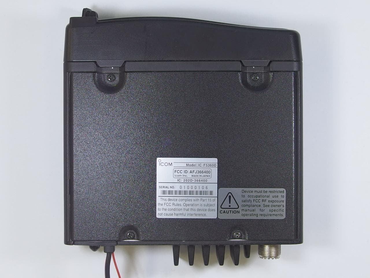
Click to zoom
Application Details
- Equipment Class
- TNB - Licensed Non-Broadcast Station Transmitter
- Date of Grant
- Jul 15, 2014
- Application Purpose
- Original Equipment
- Date of Application
- Jul 15, 2014
- Equipment Note
- VHF Digital Transceiver
- Frequency Range
- 136.00000000 - 174.00000000
- Company
- ICOM Incorporated
- Country
- Japan
Documents & Files
Document Text
Text extracted from the exhibit documents filed with the FCC. Open a document above to read the original.
Users Manual
OPERATING INSTRUCTIONS iF5360D 8 NXDN OPERATION <CONVENTIONAL MODE> 7 NXDN OPERATION <TRUNKING MODE> 6 NXDN OPERATION <COMMON> 5 MENU SCREEN 4 SCAN OPERATION 3 ADVANCED OPERATION 2 BASIC OPERATION 1 PANEL DESCRIPTION INTRODUCTION VHF DIGITAL TRANSCEIVERS iF6360D UHF DIGITAL TRANSCEIVERS i INTRODUCTION FOREWORD Thank you for purchasing this Icom transceiver. The IDAS ™ NXDN ™ system operation is built into your IC-F5360D v h f digital t r a n s c e i v e r s and IC-F6360D u h f digital t r a n s c e i v e r s. IMPORTANT FIRST, CAREFULLY READ INSTRUCTIONS q PRECAUTIONS and w INSTRUCTIONS that are provided with the transceiver. SAVE THIS OPERATING INSTRUCTIONS— This operating instructions contain additional important operating instructions for the IC-F5360D v h f digital t r a n s c e i v e r s and IC-F6360D u h f digital t r a n s c e i v- e r s. NOTE The display contents, and the hold down time period of some keys, may vary from the description in this manu- al, depending on the transceiver’s presetting. Icom, Icom Inc. and the Icom logo are registered trademarks of Icom Incorporated (Japan) in Japan, the United States, the United Kingdom, Germany, France, Spain, Russia and/ or other countries. IDAS is trademark of Icom Incorporated (Japan). NXDN is a trademark of Icom Incorporated and JVC KEN- WOOD Corporation. All other products or brands are registered trademarks or trademarks of their respective holders. 1-1 Section 1 PANEL DESCRIPTION Front, top and side panels ......................................................1-2 Microphone D..............................................................................1-2 Function display ......................................................................1-3 Programmable function keys .................................................1-4 1 PANEL DESCRIPTION 1-2 Front, top and side panels q LED INDICATOR Lights red while transmitting. ➥ Lights green while receiving a signal, or when the ➥ squelch is open. w FUNCTION DISPLAY (p. 1-3) Displays a variety of information. e DEALER-PROGRAMMABLE KEYS [UP] and [DOWN] Desired functions can be preset. (p. 1-5) r POWER KEY [] Push and hold for 1 second to turn the power ON and OFF. t DEALER-PROGRAMMABLE KEYS [R], [P0], [P1], [P2], [P3] Desired functions can be preset. (p. 1-5) y MICROPHONE CONNECTOR Connect the supplied or optional microphone. NEVER connect non-specified microphones. The pin assignments may be different and the trans- ceiver may be damaged. u AF VOLUME CONTROL KNOB [VOL] Rotate to adjust the audio output level. Microphone D The supplied or optional microphone has a PTT switch and a hanger hook. • The following functions are available when the micro- phone is on or off hook (depending on the presetting): - Pauses scan when it is off-hook. - Switches to the ‘Inaudible’ mode (mute mode) when it is on-hook. - Switches to the ‘Audible’ mode (unmute mode) when it is off-hook. u AF VOLUME CONTROL KNOB [VOL] q LED INDICATORe DEALER PROGRAMMABLE KEYS [UP], [DOWN] r POWER KEY [] t DEALER-PROGRAMMABLE KEYS [R], [P0], [P1], [P2], [P3] w FUNCTION DISPLAY SPEAKER y MICROPHONE CONNECTOR 1 PANEL DESCRIPTION 1-3 Function display q SIGNAL STRENGTH INDICATOR Displays the relative receive signal strength. w LOW OUTPUT POWER ICON Displayed when low output power is selected. e AUDIBLE ICON Displayed when the channel is in the ‘audible’ (un- mute) mode. r SCRAMBLER ICON Displayed when the Voice Scrambler function is ON. t SCAN ICON Displayed while scanning. y MESSAGE ICON Displayed when a received message (Short Data ➥ Message or Status Message) is stored in the memory stack. Blinks when an unread message is in the memory ➥ stack. u BELL ICON Blinks when a matched signal is received, depend- ing on the presetting. i GPS ICON Displayed when position data is received. o HORN ALERT ICON Displayed when the Horn Alert function is ON. !0 PUBLIC ADDRESS ICON Displayed when the Public Address function is ON. !1 ALPHANUMERIC READOUT Displays the operating channel number, channel name, menu contents, DTMF code, and so on. • The display mode automatically switches between one line and two lines. !2 KEY ICONS Display the assigned function of the [P0], [P1], [P2] and [P3] dealer assignable keys. !3 SCAN TARGET ZONE ICON Displayed when the scan target zone is selected. !4 PA SPEAKER ICON Displayed when the External speaker function is ON. When the External speaker function is ON, the PA speaker that is connected to the D-Sub 15-pin will activate. !5 AUX A ICON Displayed when the AUX A port is activate. !6 AUX B ICON Displayed when the AUX B port is activate. !7 SCAN TARGET CHANNEL ICON Displayed when the scan target channel is selected. !8 OPERATOR SELECTABLE TONE ICON Displayed when the OST (Operator Selectable Tone) function is ON. IC-F5360D CONTACT q w e r tyuio !0 !2 !1 !3!4!5 !6 !7 !8 1 PANEL DESCRIPTION 1-4 Programmable function keys The programmable key functions can be assigned to the following keys: [R], [P0], [P1], [P2], [P3], [UP], [DOWN] and to the key- pad keys of the optional DTMF microphone. [UP], [DOWN] [R], [P0], [P1], [P2], [P3] 1 PANEL DESCRIPTION 1-5 Programmable function keys (Continued) • For [R], [P0], [P1], [P2], [P3], [UP] and [DOWN] The key names that are in quotation marks in the fol- lowing explanations are displayed on the Function Dis- play, and indicate the assigned function of [P0], [P1], [P2] and [P3]. None No function Autodial “ADAL” (p. 3-2) Opens the DTMF Autodial code selection screen. Autodial Programming “ADPG” (p. 3-3) Enters the DTMF code programming mode. AUX A “AUXA” Turns the AUX A port ON or OFF. AUX B “AUXB” Turns the AUX B port ON or OFF. Broadcast “BCST” Toggles between Broadcast Call and Conference Call. This key can also be used to make a Broadcast Group Call. Call 1 “CAL1” Sends the NXDN Status, NXDN Individual or the DTMF code that is set to Call 1. Call 2 “CAL2” Sends the NXDN Status, NXDN Individual or the DTMF code that is set to Call 2. Call 3 “CAL3” Sends the NXDN Stat…
Text truncated - open the document above for the full version.
Cover Letter(s)
July 09, 2014 Ultratech Engineering Labs, Inc. 3000 Bristol Circle Oakville, Ontario L6H 6G4 Subject: Equipment Certification under FCC 47 CFR, Parts 2, 22, 74, 80 and 90 (Subpart I) - Non-Broadcast Radio Transceivers Operating in the Frequency Band 136-174 MHz (25 kHz, 12.5 kHz and 6.25 kHz Channel Spacing) Applicant: ICOM Incorporated Product: VHF Digital Transceiver Model: IC-F5360D FCC ID: AFJ366400 Dear Sir/Madam: As appointed agent for ICOM Incorporated, we would like to submit the application to you for FCC certification of the above product. Please review all files uploaded to your electronic filing site. Note 1: As declared by the applicant in the attestation letter submitted with this filing, 25kHz channel spacing (16K0F3E) operation of this radio is permanently disabled for Part 90 use as required by FCC mandate. Test performed for 25kHz channel spacing are for parts 22, 74 & 80 certifications only. Note 2: ICOM hereby request FCC to list the entire frequency range from 136-174 MHz under FCC rules as per the reasons explained in the attached Frequency Justification letter submitted with this filing. If you have any queries, please do not hesitate to contact us. Yours truly, Dharmajit Solanki Dharmajit Solanki Authorized Agent UltraTech Group of Labs FCC TCB & IC CB Ultratech’s Accreditations: 0685 91038 1309 46390-2049 NVLAP LAB CODE 200093-0 SL2-IN-E-1119R Korea KCC-RRA CA2049 TL363_B TPTDP DA1300 3000 Bristol Circle, Oakville, Ontario, Canada L6H 6G4 Tel.: (905) 829-1570 Fax.: (905) 829-8050 Website: www.ultratech-labs.com Email: [email protected]
External Photos
Photographs of the equipment Front view Rear view Photographs of the equipment Front view Rear view Photographs of the equipment Right view Left view Photographs of the equipment Right view Left view Photographs of the equipment Top view Bottom view Photographs of the equipment Top view Bottom view
Internal Photos
Photographs of the equipment MAIN Board Side-A MAIN Board Side-B Photographs of the equipment MAIN Board Side-A MAIN Board Side-B Photographs of the equipment FRONT Board Side-A FRONT Board Side-B Photographs of the equipment FRONT Board Side-A FRONT Board Side-B Photographs of the equipment CONNECT Board Side-A CONNECT Board Side-B Photographs of the equipment CONNECT Board Side-A CONNECT Board Side-B
RF Exposure Info
WORDDEFINITION RDANGER!Personal death, serious injury or an explosion may occur. RWARNING!Personal injury, fire hazard or electric shock may occur. CAUTIONEquipment damage may occur. NOTEIf disregarded, inconvenience only. No risk of personal injury, fire or electric shock. Thank you for choosing the IC-F5360D v h f digital t r a n s c e i v e r or IC-F6360D u h f digital t r a n s c e i v e r. READ ALL PRECAUTIONS carefully and complete- ly before using your transceiver. 1-1-32 Kamiminami, Hirano-ku, Osaka 547-0003, Japan A-7148?-1EX Printed in Japan © 2014 Icom Inc. PRECAUTIONS VHF DIGITAL TRANSCEIVER Iç-F6360D UHF DIGITAL TRANSCEIVER Iç-F5360D RWARNING! NEVER connect the radio to an AC outlet. This may pose a fire hazard or result in an electric shock. RWARNING! NEVER connect the radio to a power source of more than 16 V DC such as a 24 V battery. This will ruin the radio. RWARNING! NEVER cut the DC power cable between the DC plug and fuse holder. If an incorrect connection is made after cutting, the radio might be damaged. RWARNING! NEVER place the radio where normal operation of the vehicle may be hindered or where it could cause bodily injury. CAUTION: NEVER allow children to touch the radio. CAUTION: NEVER expose the radio to rain, snow or any liquids. USE the specified microphone only. Other microphones have different pin assignments and may damage the radio. DO NOT use or place the radio in areas with temperatures below –30°C (–22°F) or above +60°C (+140°F), or in areas subject to direct sunlight, such as the dashboard. DO NOT operate the radio without running the vehicle’s en- gine. The vehicle’s battery will quickly run out when the radio transmits while the vehicle’s engine is OFF. DO NOT place the radio in excessively dusty environ- ments. DO NOT place the radio against walls. Otherwise heat dis- sipation will be obstructed. DO NOT use chemical agents such as benzine or alcohol when cleaning, as they damage the radio surfaces. BE CAREFUL! The radio will become hot when operating continuously for long periods. EXPLICIT DEFINITIONS PRECAUTIONS The GPS receiver may not work if the radio transmits near the 510 MHz. This is made in the internal circuit and does not indicate a radio malfunction. Icom, Icom Inc. and the Icom logo are registered trademarks of Icom Incor- porated (Japan) in Japan, the United States, the United Kingdom, Germany, France, Spain, Russia and/or other countries. AMBE+2 is a trademark and property of Digital Voice Systems Inc. All other products or brands are registered trademarks or trademarks of their respective holders. • FOR CLASS A UNINTENTIONAL RADIATORS: This equipment has been tested and found to comply with the limits for a Class A digital device, pursuant to part 15 of the FCC Rules. These limits are designed to provide rea- sonable protection against harmful interference when the equipment is operated in a commercial environment. This equipment generates, uses, and can radiate radio frequency energy and, if not installed and used in accordance with the instruction manual, may cause harmful interference to radio communications. Operation of this equipment in a residential area is likely to cause harmful interference in which case the user will be required to correct the interference at his own expense. This device complies with Part 15 of the FCC Rules. Opera- tion is subject to the condition that this device does not cause harmful interference. CAUTION: Changes or modifications to this transceiver, not expressly approved by Icom Inc., could void your authority to operate this transceiver under FCC regulations. • ISO 3166-1 CountryCodesCountryCodes 1 2 3 4 5 6 7 8 9 10 11 12 13 14 15 16 17 Austria Belgium Bulgaria Croatia Czech Republic Cyprus Denmark Estonia Finland France Germany Greece Hungary Iceland Ireland Italy Latvia AT BE BG HR CZ CY DK EE FI FR DE GR HU IS IE IT LV 18 19 20 21 22 23 24 25 26 27 28 29 30 31 32 33 Liechtenstein Lithuania Luxembourg Malta Netherlands Norway Poland Portugal Romania Slovakia Slovenia Spain Sweden Switzerland Turkey United Kingdom LI LT LU MT NL NO PL PT RO SK SI ES SE CH TR GB < Intended Country of Use > AT FI IT PL GB RO BE FR LV PT IS TR CY DE LT SK LI HR CZ GR LU SI NO DK HU MT ES CH EE IE NL SE BG The AMBE+2™ voice coding Technology embodied in this product is protected by intellectual property rights including patent rights, copyrights and trade secrets of Digital Voice Systems, Inc. This voice coding Technology is licensed solely for use within this Communications Equipment. The user of this Technology is explicitly prohibited from attempting to ex- tract, remove, decompile, reverse engineer, or disassemble the Object Code, or in any other way convert the Object Code into a human-readable form. U.S. Patent Nos. #5,870,405, #5,826,222, #5,754,974, #5,701,390, #5,715,365, #5,649,050, #5,630,011, #5,581,656, #5,517,511, #5,491,772, #5,247,579, #5,226,084 and #5,195,166. FCC INFORMATIONCOUNTRY CODE LIST VOICE CODING TECHNOLOGY • POUR LES RAYONNEMENTS NON INTENTIONNELS DE CLASSE A: Cet équipement a été testé et reconnu conforme aux limites fixées pour un appareil numérique de classe A, conformé- ment au point 15 de la réglementation FCC. Ces limites assurent une protection raisonnable contre les interférences nuisibles lorsque l'équipement est utilisé dans un environnement commercial. Cet équipement génère une énergie de radio fréquence, utilise et rayonner et s'il n'est pas installé et utilisé conformément au manuel d'instruction, peut causer des interférences nuisibles aux communica- tions radio. Le fonctionnement de cet équipement dans une zone résidentielle est susceptible de causer des interféren- ces nuisibles lorsque l'utilisateur doit corriger les interféren- ces à ses propres frais. Cet appareil respecte les conditions établies au paragraphe 15 des règles de la FCC. Son utilisation est assujettie à la condition de ne pas provoquer des interférences nuisibles. MISE EN GARDE: Tout changement ou modifi…
Text truncated - open the document above for the full version.
Test Report
VHF Digital Transceiver Model No.: IC-F5360D FCC ID: AFJ366400 Applicant: ICOM Incorporated 1-1-32, Kamiminami, Hirano-ku Osaka, Japan, 547-0003 Tested in Accordance With Federal Communications Commission (FCC) 47 CFR, Parts 2, 22, 74, 80 and 90 (Subpart I) UltraTech's File No.: ICOM-371Q_FCC90 This Test report is Issued under the Authority of Tri M. Luu, Professional Engineer, Vice President of Engineering UltraTech Group of Labs Date: July 09, 2014 Report Prepared by: Dharmajit Solanki Issued Date: July 09, 2014 Tested by: Wei Wu Test Dates: June 25- July 04, 2014 The results in this Test Report apply only to the sample(s) tested, and the sample tested is randomly selected. This report must not be used by the client to claim product endorsement by NVLAP or any agency of the US Government. UltraTech 3000 Bristol Circle, Oakville, Ontario, Canada, L6H 6G4 Tel.: (905) 829-1570 Fax.: (905) 829-8050 Website: www.ultratech-labs.com , Email: [email protected], Email: [email protected] Korea KCC-RRA 91038 1309 46390-2049 NVLAP LAB CODE 200093-0 SL2-IN-E- 1119R CA2049 TL363_B TPTDP DA1300 FCC Parts 2, 22, 74, 80 and 90 Subpart I, Non-Broadcast Radio Transceivers Contents i VHF Digital Transceiver, Model IC-F5360D FCC ID: AFJ366400 ULTRATECH GROUP OF LABS File #: ICOM-371Q_FCC90 3000 Bristol Circle, Oakville, Ontario, Canada L6H 6G4 July 09, 2014 Tel. #: 905-829-1570, Fax. #: 905-829-8050, Email: [email protected] , Website: http://www.ultratech-labs.com All test results contained in this engineering test report are traceable to National Institute of Standards and Technology (NIST) TABLE OF CONTENTS EXHIBIT 1. INTRODUCTION ............................................................................................................................................ 1 1.1. SCOPE............................................................................................................................................................................ 1 1.2. RELATED SUBMITTAL(S)/GRANT(S) ...................................................................................................................... 1 1.3. NORMATIVE REFERENCES....................................................................................................................................... 1 EXHIBIT 2. PERFORMANCE ASSESSMENT.................................................................................................................. 2 2.1. CLIENT INFORMATION ............................................................................................................................................. 2 2.2. EQUIPMENT UNDER TEST (EUT) INFORMATION................................................................................................. 2 2.3. EUT’S TECHNICAL SPECIFICATIONS ..................................................................................................................... 3 2.4. LIST OF EUT’S PORTS................................................................................................................................................. 4 2.5. ANCILLARY EQUIPMENT ......................................................................................................................................... 4 2.6. GENERAL TEST SETUP .............................................................................................................................................. 4 EXHIBIT 3. EUT OPERATING CONDITIONS AND CONFIGURATIONS DURING TESTS................................... 5 3.1. CLIMATE TEST CONDITIONS ................................................................................................................................... 5 3.2. OPERATIONAL TEST CONDITIONS & ARRANGEMENT FOR TEST SIGNALS.................................................. 5 EXHIBIT 4. SUMMARY OF TEST RESULTS .................................................................................................................. 6 4.1. LOCATION OF TESTS ................................................................................................................................................. 6 4.2. APPLICABILITY & SUMMARY OF EMISSION TEST RESULTS............................................................................ 6 4.3. MODIFICATIONS INCORPORATED IN THE EUT FOR COMPLIANCE PURPOSES ............................................ 6 EXHIBIT 5. MEASUREMENTS, EXAMINATIONS & TEST DATA FOR EMC EMISSIONS .................................. 7 5.1. TEST PROCEDURES .................................................................................................................................................... 7 5.2. MEASUREMENT UNCERTAINTIES.......................................................................................................................... 7 5.3. MEASUREMENT EQUIPMENT USED ....................................................................................................................... 7 5.4. ESSENTIAL/PRIMARY FUNCTIONS AS DECLARED BY THE MANUFACTURER ............................................ 7 5.5. RF POWER OUTPUT [§§ 2.1046, 22.565, 74.461, 80.215 & 90.205] ........................................................................... 8 5.6. AUDIO FREQUENCY RESPONSE [§ 2.1047(A), 80.213(E) & 90.242(B)(8)].............................................................. 9 5.7. MODULATION LIMITING [§§ 2.1047 (B), 74.463, 80.213 & 90.210]....................................................................... 14 5.8. OCCUPIED BANDWIDTH & EMISSION MASK [§§ 2.1049, 74.462, 80.211(F), 90.209 & 90.210] ........................ 19 5.9. TRANSMITTER ANTENNA POWER SPURIOUS/HARMONIC CONDUCTED EMISSIONS [§§ 2.1051, 2.1057, 22.359, 80.211(F)(3) & 90.210] ................................................................................................................................................ 57 5.10. TRANSMITTER SPURIOUS/HARMONIC RADIATED EMISSIONS [§§ 2.1053, 2.1057, 22.359, 80.211(F)(3) & 90.210] .........…
Text truncated - open the document above for the full version.
Test Setup Photos
ANNEX 1 - TEST SETUP PHOTOGRAPHS ICOM Incorporated VHF Digital Transceiver, M/N: IC-F5360D FCC ID: AFJ366400, IC: 202D-366400 Plot #1: Tx Radiated Emission Test Setup ANNEX 1 - TEST SETUP PHOTOGRAPHS ICOM Incorporated VHF Digital Transceiver, M/N: IC-F5360D FCC ID: AFJ366400, IC: 202D-366400 Plot #2: Tx Radiated Emission Test Setup ANNEX 1 - TEST SETUP PHOTOGRAPHS ICOM Incorporated VHF Digital Transceiver, M/N: IC-F5360D FCC ID: AFJ366400, IC: 202D-366400 Plot #3: Tx Radiated Emission Test Setup
Contact Information
Applicant
Tatsuo Yano(General Manager of QA Department)
Test Firm
UltraTech Engineering Labs Inc.Tri Luu
Technical Specifications
| # | Rule Parts | Frequency Range | Power Output | Emission | Tolerance |
|---|---|---|---|---|---|
| 12 | 22,74,8 | 136 MHz - 174 MHz | 5 W | 16K0F3E | 1 ppm |
Other Applications from ICOM Incorporated

AFJ453700
Jul 23, 2026Mobile Transceiver
Equipment Class
DTS - Digital Transmission System
AFJ452000
Jun 02, 2026VHF DIGITAL TRANSCEIVER
Equipment Class
TNF - Licensed Non-Broadcast Transmitter Held to Face
AFJ452100
May 12, 2026UHF DIGITAL TRANSCEIVER
Equipment Class
TNF - Licensed Non-Broadcast Transmitter Held to Face
AFJ444500
Sep 12, 2024Scanning Receiver
Equipment Class
CSR - Scanning Receiver
AFJ410900
Jul 09, 2024Linear Amplifier
Equipment Class
AMP - Amplifier