AFJAP-3Access Point
ICOM Incorporated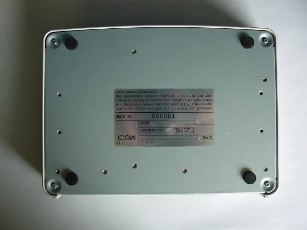
Click to zoom
Application Details
- Equipment Class
- JBP - Part 15 Class B Computing Device Peripheral
- Date of Grant
- Dec 28, 2000
- Application Purpose
- Original Equipment
- Date of Application
- Dec 28, 2000
- Equipment Note
- Access Point
- Company
- ICOM Incorporated
- Country
- Japan
Documents & Files
Document Text
Text extracted from the exhibit documents filed with the FCC. Open a document above to read the original.
Users Manual
INSTRUCTION MANUAL WIRELESS ACCESS POINT AP-3 This device complies with Part 15 of the FCC Rules. Operation is subject to the following two conditions: (1) this device may not cause harmful interference and (2) this device must accept any interference received, includ- ing interference that my cause undesired operation. Thank you for purchasing an ICOM WAVEMASTER wireless access point. This wireless access point is provided with the functions nec- essary for supporting a wireless LAN. This manual is designed to help you use your new wireless access point to its fullest potential. Read this manual careful- ly before using the wireless access point. TRADEMARK CREDITS WAVEMASTER is a registered trademark of ICOM Inc. Windows is a registered trademark of Microsoft Corporation in the United States and/or other countries. The screen shots that appear within this text are used with permission of Microsoft Corporation. Macintosh and Mac-OS are registered trademarks of Apple Computer, Inc., in the United States. Netscape Navigator is a trademark of Netscape Communications Corporation. Other product and company names mentioned herein are the trademarks or registered trademarks of their respective owners. INTRODUCTION SUMMARY OF FEATURES lAll settings can be adjusted using a web browser. lNetworks combining wireless LAN and wired LAN components can be constructed with ease. lIncludes both wireless access point functions (including roaming) and wireless bridge functions. lSupports 11-Mbps wireless access point communications and 100BASE-TX wired LAN communications. lSupports all ICOM wireless LAN cards (as of May 2000). lIncludes such advanced security functions as ESS ID settings, MAC address registration, and WEP encryption. USER REGISTRATION Be sure to fill out the user registration card and return it to us. You must return the card to be eligible for technical support and ser- vice. INTRODUCTION INTRODUCTION WIRELESS LAN CARD This wireless access point is designed for use with an 11-Mbps wireless LAN card. When setting the wireless access point to a channel (see p. 47) other than channel 11, be sure to read “Precautions Regarding Radio Interference.” PRECAUTIONS REGARDING RADIO INTERFERENCE The frequency band used by this wireless access point is also used by microwave ovens and other industrial, scientific, and medical devices, as well as the indoor wireless stations (requiring a license) used for identify- ing the mobile devices utilized on factory production lines and designated low-power wireless stations (not requiring a license). 1. Before using this access point, make sure no indoor wireless stations for mobile device identification or designated low-power wireless stations are being operated nearby. 2. If this access point interferes with the operation of an indoor wireless stations for mobile device identification, change the operating frequen- cy of the access point immediately or stop the signal transmission and contact your dealer or our service department to discuss measures for preventing signal interference (such as installing a partition). 3. If this access point interferes with the operation of a designated low- power wireless station or causes any other problems, contact your deal- er or our service department at the telephone number indicated below. Service Department, ICOM AMERICA, INC. INTRODUCTION STANDARD PACKING LIST qAP-3 ·········································································1 unit wMain unit mounting hardware ··································1 set eAC adapter (BC-123A)·············································1 piece rEthernet cable ··························································1 piece * (For connecting to Ethernet port) tFerrite core (Be sure to install this item. (+p. 9)····1 piece lUtility Software disks (for AP-3) ·······························2 disks lUser registration card···············································1 piece lInstruction manual lWarranty sheets (for both AP-3 and SL-1100) HSL-1100 or SL-1105 wireless LAN card is an option CONTENTS 1. SAFETY PRECAUTIONS—————————————1-5 n FCC precautions ····················································5 2. PANEL DESCRIPTION——————————————6-9 n Front and rear panels ············································6 3. BEFORE CONNECTING CABLES——————————9 3-1 Attaching the Ferrite Core ··········································9 3-2 Selecting an Installation Site ······································9 3-3 Inserting the Wireless LAN Card ······························10 n Precautions ··························································10 3-4 Mounting the AP-3 Unit ·············································11 1. Attach the mounting fittings to the unit·················11 2. Mount the AP-3 unit ·············································11 3-5 Connection Precautions············································13 4. CABLE CONNECTIONS——————————————14 4-1 Connecting to a Computer········································14 4-2 Connecting to a HUB ················································15 4-3 Other Connections ····················································16 5. COMPUTER SETTINGS——————————————17 5-1 Network Settings·······················································17 ÅCheck Ethernet card ············································17 ıCheck protoco ······················································17 ÇCheck TCP/IP settings ·········································17 Ç-1 Windows 95 and 98 ·····································18 Ç-2 Windows NT 4.0 (WorkStation)····················21 Ç-3 Windows 2000 (Professional) ······················25 Ç-4 MAC OS ·······················································32 5-2 Setting Tips ·······························································33 5-3 Checking the Network Settings ································34 n Windows 95 and 98 ·············································34 n Windows NT 4.0 (Work Station) or Wind…
Text truncated - open the document above for the full version.
Users Manual
INSTRUCTION MANUAL WIRELESS ACCESS POINT AP-3 This device complies with Part 15 of the FCC Rules. Operation is subject to the following two conditions: (1) this device may not cause harmful interference and (2) this device must accept any interference received, includ- ing interference that my cause undesired operation. Thank you for purchasing an ICOM WAVEMASTER wireless access point. This wireless access point is provided with the functions nec- essary for supporting a wireless LAN. This manual is designed to help you use your new wireless access point to its fullest potential. Read this manual careful- ly before using the wireless access point. TRADEMARK CREDITS WAVEMASTER is a registered trademark of ICOM Inc. Windows is a registered trademark of Microsoft Corporation in the United States and/or other countries. The screen shots that appear within this text are used with permission of Microsoft Corporation. Macintosh and Mac-OS are registered trademarks of Apple Computer, Inc., in the United States. Netscape Navigator is a trademark of Netscape Communications Corporation. Other product and company names mentioned herein are the trademarks or registered trademarks of their respective owners. INTRODUCTION SUMMARY OF FEATURES lAll settings can be adjusted using a web browser. lNetworks combining wireless LAN and wired LAN components can be constructed with ease. lIncludes both wireless access point functions (including roaming) and wireless bridge functions. lSupports 11-Mbps wireless access point communications and 100BASE-TX wired LAN communications. lSupports all ICOM wireless LAN cards (as of May 2000). lIncludes such advanced security functions as ESS ID settings, MAC address registration, and WEP encryption. USER REGISTRATION Be sure to fill out the user registration card and return it to us. You must return the card to be eligible for technical support and ser- vice. INTRODUCTION INTRODUCTION WIRELESS LAN CARD This wireless access point is designed for use with an 11-Mbps wireless LAN card. When setting the wireless access point to a channel (see p. 47) other than channel 11, be sure to read “Precautions Regarding Radio Interference.” PRECAUTIONS REGARDING RADIO INTERFERENCE The frequency band used by this wireless access point is also used by microwave ovens and other industrial, scientific, and medical devices, as well as the indoor wireless stations (requiring a license) used for identify- ing the mobile devices utilized on factory production lines and designated low-power wireless stations (not requiring a license). 1. Before using this access point, make sure no indoor wireless stations for mobile device identification or designated low-power wireless stations are being operated nearby. 2. If this access point interferes with the operation of an indoor wireless stations for mobile device identification, change the operating frequen- cy of the access point immediately or stop the signal transmission and contact your dealer or our service department to discuss measures for preventing signal interference (such as installing a partition). 3. If this access point interferes with the operation of a designated low- power wireless station or causes any other problems, contact your deal- er or our service department at the telephone number indicated below. Service Department, ICOM AMERICA, INC. INTRODUCTION STANDARD PACKING LIST qAP-3 ·········································································1 unit wMain unit mounting hardware ··································1 set eAC adapter (BC-123A)·············································1 piece rEthernet cable ··························································1 piece * (For connecting to Ethernet port) tFerrite core (Be sure to install this item. (+p. 9)····1 piece lUtility Software disks (for AP-3) ·······························2 disks lUser registration card···············································1 piece lInstruction manual lWarranty sheets (for both AP-3 and SL-1100) HSL-1100 or SL-1105 wireless LAN card is an option CONTENTS 1. SAFETY PRECAUTIONS—————————————1-5 n FCC precautions ····················································5 2. PANEL DESCRIPTION——————————————6-9 n Front and rear panels ············································6 3. BEFORE CONNECTING CABLES——————————9 3-1 Attaching the Ferrite Core ··········································9 3-2 Selecting an Installation Site ······································9 3-3 Inserting the Wireless LAN Card ······························10 n Precautions ··························································10 3-4 Mounting the AP-3 Unit ·············································11 1. Attach the mounting fittings to the unit·················11 2. Mount the AP-3 unit ·············································11 3-5 Connection Precautions············································13 4. CABLE CONNECTIONS——————————————14 4-1 Connecting to a Computer········································14 4-2 Connecting to a HUB ················································15 4-3 Other Connections ····················································16 5. COMPUTER SETTINGS——————————————17 5-1 Network Settings·······················································17 ÅCheck Ethernet card ············································17 ıCheck protoco ······················································17 ÇCheck TCP/IP settings ·········································17 Ç-1 Windows 95 and 98 ·····································18 Ç-2 Windows NT 4.0 (WorkStation)····················21 Ç-3 Windows 2000 (Professional) ······················25 Ç-4 MAC OS ·······················································32 5-2 Setting Tips ·······························································33 5-3 Checking the Network Settings ································34 n Windows 95 and 98 ·············································34 n Windows NT 4.0 (Work Station) or Wind…
Text truncated - open the document above for the full version.
External Photos
360 Herndon Parkway Suite 1400 Herndon, VA 20170 http://www.rheintech.com Certification Report For: ICOM America Page 20 of 32 Document Number: 2000453 10 EXTERNAL PHOTOGRAPHS 360 Herndon Parkway Suite 1400 Herndon, VA 20170 http://www.rheintech.com Certification Report For: ICOM America Page 21 of 32 Document Number: 2000453 360 Herndon Parkway Suite 1400 Herndon, VA 20170 http://www.rheintech.com Certification Report For: ICOM America Page 22 of 32 Document Number: 2000453 360 Herndon Parkway Suite 1400 Herndon, VA 20170 http://www.rheintech.com Certification Report For: ICOM America Page 23 of 32 Document Number: 2000453 360 Herndon Parkway Suite 1400 Herndon, VA 20170 http://www.rheintech.com Certification Report For: ICOM America Page 24 of 32 Document Number: 2000453 360 Herndon Parkway Suite 1400 Herndon, VA 20170 http://www.rheintech.com Certification Report For: ICOM America Page 25 of 32 Document Number: 2000453
ID Label/Location Info
360 Herndon Parkway Suite 1400 Herndon, VA 20170 http://www.rheintech.com Certification Report For: ICOM America Page 17 of 32 Document Number: 2000453 8 LABEL INFORMATION FCC LABEL AND LOCATION OF LABEL ON EUT Please also see the following page.
Internal Photos
360 Herndon Parkway Suite 1400 Herndon, VA 20170 http://www.rheintech.com Certification Report For: ICOM America Page 26 of 32 Document Number: 2000453 10.1 INTERNAL PHOTOGRAPHS 360 Herndon Parkway Suite 1400 Herndon, VA 20170 http://www.rheintech.com Certification Report For: ICOM America Page 27 of 32 Document Number: 2000453 360 Herndon Parkway Suite 1400 Herndon, VA 20170 http://www.rheintech.com Certification Report For: ICOM America Page 28 of 32 Document Number: 2000453 360 Herndon Parkway Suite 1400 Herndon, VA 20170 http://www.rheintech.com Certification Report For: ICOM America Page 29 of 32 Document Number: 2000453
Operational Description
360 Herndon Parkway Suite 1400 Herndon, VA 20170 http://www.rheintech.com Certification Report For: ICOM America Page 16 of 32 Document Number: 2000453 7 PRODUCT DESCRIPTION The AP-3 Access Point is a digital interface device that allows the installation of a wireless PCMCIA Cards. The unit is self-contained with it’s own power supply and control circuitry necessary to complete a wireless transmitter interface. The device has a type III PCMCIA slot and an RS232 serial port for interfacing to a computer. Control of the wireless card is from the computer.
Test Report
Engineering and Testing for EMC and Safety Compliance 360 Herndon Parkway, Suite 1400 Herndon, VA 20170 Phone: 703-689-0368; Fax: 703-689-2056; Metro: 703-471-6441 APPLICATION FOR FCC CERTIFICATION OF A DIGITAL DEVICE ICOM Incorporated 1-6-19 Kamikurazukuri Hirano-Ku Osaka, Japan 547 Model: AP-3 Access Point FCC ID: AFJ AP-3 December 7, 2000 STANDARDS REFERENCED FOR THIS REPORT PART 2: 1999 FREQUENCY ALLOCATIONS AND RADIO TREATY MATTERS; GENERAL RULES AND REGULATIONS PART 15: 1999 RADIO FREQUENCY DEVICES FCC 97-114 GUIDANCE ON MEASUREMENTS FOR DIRECT SEQUENCE SPREAD SPECTRUM SYSTEMS ANSI C63.4-1992 STANDARD FORMAT MEASUREMENT/TECHNICAL REPORT PERSONAL COMPUTER AND PERIPHERALS FCC Rules Parts Frequency Range Output Power (W) Freq. Tolerance Emission Designator 15subpart B N/A N/A N/A N/A This report concerns (check one): Original Grant: X Class II Change: Equipment Type: PCMCIA Board Deferred grant requested per 47 CFR 0.457 (d) (1) (ii)? Yes: No: X If yes, defer until: Company name agrees to notify the Commission by: (date) of the intended date of announcement of the product so that the grant can be issued on that date. Transition Rules Request per 15.37? Yes: No: X If no, assumed Part 15, subpart B for unintentional radiators - the new 47 CFR. [10-1-90 Edition] provision. REPORT PREPARED BY: EMC Engineer: Rachid Sehb Signature: Supervising Engineer: Desmond A. Fraser Signature: Document Number: 2000453 No part of this report may be reproduced without the full written approval of Rhein Tech Laboratories, Inc. 360 Herndon Parkway Suite 1400 Herndon, VA 20170 http://www.rheintech.com Certification Report For: ICOM America Page 2 of 32 Document Number: 2000453 TABLE OF CONTENTS 1 INTRODUCTION....................................................................................................................................................3 1.1 RELATED SUBMITTAL(S)/GRANT(S).......................................................................................................3 1.2 TEST METHODOLOGY.................................................................................................................................3 1.3 TEST FACILITY...............................................................................................................................................3 1.4 EMISSIONS EQUIPMENT LIST....................................................................................................................4 2 SYSTEM TEST CONFIGURATION...................................................................................................................7 2.1 JUSTIFICATION...............................................................................................................................................7 2.2 EUT EXERCISE SOFTWARE........................................................................................................................7 2.3 SPECIAL ACCESSORIES...............................................................................................................................7 2.4 TEST SYSTEM DETAILS...............................................................................................................................8 2.5 CONFIGURATION OF TESTED SYSTEM..................................................................................................9 3 CONFORMANCE STATEMENT......................................................................................................................10 4 FIELD STRENGTH CALCULATION..............................................................................................................11 5 CONDUCTED EMISSIONS MEASUREMENTS............................................................................................12 5.1 CONDUCTED EMISSIONS TEST...............................................................................................................13 5.1.1 CONDUCTED EMISSIONS (CHANNEL 1 WITH THE INTERNAL ANTENNA)..............................13 6 RADIATED EMISSIONS MEASUREMENTS................................................................................................14 6.1 RADIATED EMISSIONS TEST.............................................................................................................................15 6.1.1 Radiated Emissions Digital noise (Channel 1 with the Internal Antenna).........................................15 7 PRODUCT DESCRIPTION.................................................................................................................................16 8 LABEL INFORMATION.....................................................................................................................................17 9 TEST PHOTOGRAPHS.......................................................................................................................................18 9.1 CONDUCTED MEASUREMENT PHOTOS.............................................................................................................18 9.2 RADIATED MEASUREMENT PHOTOS................................................................................................................19 10 EXTERNAL PHOTOGRAPHS.......................................................................................................................20 10.1 INTERNAL PHOTOGRAPHS................................................................................................................................26 11 SCHEMATICS...................................................................................................................................................30 12 BLOCK DIAGRAM..........................................................................................................................................31 13 MANUAL............................................................................................................................................................32 360 Herndon Parkway Suite 1400 Herndon, VA…
Text truncated - open the document above for the full version.
Test Setup Photos
360 Herndon Parkway Suite 1400 Herndon, VA 20170 http://www.rheintech.com Certification Report For: ICOM America Page 18 of 32 Document Number: 2000453 9 TEST PHOTOGRAPHS 9.1 CONDUCTED MEASUREMENT PHOTOS Front view Rear view 360 Herndon Parkway Suite 1400 Herndon, VA 20170 http://www.rheintech.com Certification Report For: ICOM America Page 19 of 32 Document Number: 2000453 9.2 RADIATED MEASUREMENT PHOTOS Front view Rear view
Contact Information
Applicant
Atsushi Tomiyama(General Manager)
Technical Contact
Rhein Tech laboratories, Inc.Desmond Fraser
[email protected]703 689 0368
360 Herndom Parkway · Herndon, Virginia · United States
Test Firm
Rhein Tech Laboratories, Inc.Rick McMurray
Technical Specifications
| # | Rule Parts | Frequency Range | Power Output |
|---|---|---|---|
| 1 | 15B | - | - |
Other Applications from ICOM Incorporated

AFJ453700
Jul 23, 2026Mobile Transceiver
Equipment Class
DTS - Digital Transmission System
AFJ452000
Jun 02, 2026VHF DIGITAL TRANSCEIVER
Equipment Class
TNF - Licensed Non-Broadcast Transmitter Held to Face
AFJ452100
May 12, 2026UHF DIGITAL TRANSCEIVER
Equipment Class
TNF - Licensed Non-Broadcast Transmitter Held to Face
AFJ444500
Sep 12, 2024Scanning Receiver
Equipment Class
CSR - Scanning Receiver
AFJ410900
Jul 09, 2024Linear Amplifier
Equipment Class
AMP - Amplifier