AFJIC-F4G-3Non-Broadcast Transmitter Held to Face
ICOM Incorporated
Click to zoom
Application Details
- Equipment Class
- TNF - Licensed Non-Broadcast Transmitter Held to Face
- Date of Grant
- Feb 04, 2001
- Application Purpose
- Original Equipment
- Date of Application
- Jul 06, 2000
- Equipment Note
- Non-Broadcast Transmitter Held to Face
- Frequency Range
- 470.00000000 - 500.00000000
- Company
- ICOM Incorporated
- Country
- Japan
Documents & Files
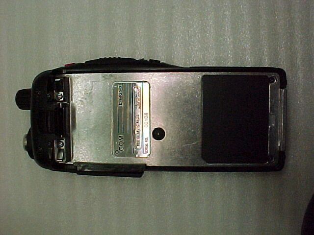
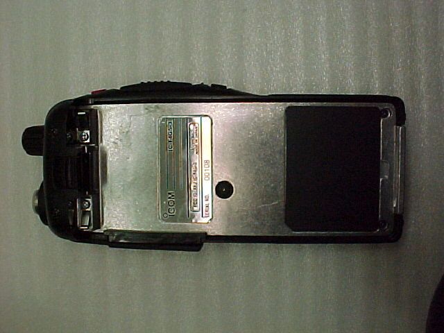
Document Text
Text extracted from the exhibit documents filed with the FCC. Open a document above to read the original.
Users Manual
ii i FOREWORDThank you for purchasing the IC-F3GT/GS,IC-F4GT/GS FM trans-ceiver.READ ALL INSTRUCTIONS carefully and completely before using the transceiver.SAVE THIS INSTRUCTION MANUAL– This instruction manual con- tains important operating instructions for the transceiver.IMPORTANTR CAUTION! NEVER hold the transceiver so that the antenna is very close to, or touching exposed parts of the body, especially theface or eyes, while transmitting. The transceiver will perform best ifthe microphone is 2 to 4 in. (5 to 10 cm) away from the lips and thetransceiver is vertical.R CAUTION! NEVER operate the transceiver with a headset or other audio accessories at high volume levels.R CAUTION! NEVER short the terminals of the battery pack. DO NOT push the PTT when not actually desiring to transmit. AVOID using or placing the transceiver in direct sunlight or in areas with temperatures below +14°F (–10°C) or above +122°F (+50°C).DO NOT modify the transceiver for any reason. KEEP the transceiver from the heavy rain, and Never immerse it in the water. The transceiver construction is water resistant , not water proof.The use of non-Icom battery packs/chargers may impair transceiverperformance and invalidate the warranty. FCC caution: Changes or modifications to this transceiver, not expressly approved by Icom Inc., could void your authority to op-erate this transceiver under FCC regulations. TABLE OF CONTENTSFOREWORD . . . . . . . . . . . . . . . . . . . . . . . . . . . . . . . . . . . . . . . . . . .iIMPORTANT . . . . . . . . . . . . . . . . . . . . . . . . . . . . . . . . . . . . . . . . . . .iTABLE OF CONTENTS . . . . . . . . . . . . . . . . . . . . . . . . . . . . . . . . . .ii1 PANEL DESCRIPTION . . . . . . . . . . . . . . . . . . . . . . . . . . . . . .1–3 ‘ Switches, controls, keys and connectors . . . . . . . . . . . . . . .1–2 ‘ Function display . . . . . . . . . . . . . . . . . . . . . . . . . . . . . . . . . . . .3 2 ACCESSORIES . . . . . . . . . . . . . . . . . . . . . . . . . . . . . . . . . . . . . .43 BATTERY PACKS . . . . . . . . . . . . . . . . . . . . . . . . . . . . . . . . .5–10 ‘ Battery pack replacement . . . . . . . . . . . . . . . . . . . . . . . . . . . .5 ‘ Battery cautions . . . . . . . . . . . . . . . . . . . . . . . . . . . . . . . . . . . .6 ‘ Battery charging . . . . . . . . . . . . . . . . . . . . . . . . . . . . . . . . . .7-8 ‘ Charging NOTE . . . . . . . . . . . . . . . . . . . . . . . . . . . . . . . . . . .9 ‘ Battery case (Option) . . . . . . . . . . . . . . . . . . . . . . . . . . . . . .10 44 PP RR OO GG RR AA MM MM AA BB LL EE FF UU NN CC TT II OO NN SS .. .. .. .. .. .. .. .. .. .. .. .. .. .. .. .. .. .. .. .. .. 11-15 ‘ Receiving and transmitting . . . . . . . . . . . . . . . . . . . . . . . . . .11 5 CONVENTIONAL OPERATION . . . . . . . . . . . . . . . . . . . . . .16-18 ‘ Call procedure . . . . . . . . . . . . . . . . . . . . . . . . . . . . . . . . . . . .17 ‘ Tx code channel selection . . . . . . . . . . . . . . . . . . . . . . . . . . .18 ‘ Manual 5-tone codes . . . . . . . . . . . . . . . . . . . . . . . . . . . . . . .18 ‘ Transmitting notes . . . . . . . . . . . . . . . . . . . . . . . . . . . . . . . . .18 6 SMARTRUNK II TM OPERATION . . . . . . . . . . . . . . . . . . . . . .19-21 ‘ Basic operation . . . . . . . . . . . . . . . . . . . . . . . . . . . . . . . . . . .19 7 OTHER FUNCTIONS . . . . . . . . . . . . . . . . . . . . . . . . . . . . . . . . .22 ‘ DTMF pager/Code squelch . . . . . . . . . . . . . . . . . . . . . . . . . .22 8 MAINTENANCE . . . . . . . . . . . . . . . . . . . . . . . . . . . . . . . . . . . . .23 ‘ Optional UT-105/UT-108/UT-109 and UT-110 installation . .23 9 CLONING . . . . . . . . . . . . . . . . . . . . . . . . . . . . . . . . . . . . . . . . . .2410 OPTIONS . . . . . . . . . . . . . . . . . . . . . . . . . . . . . . . . . . . . . . .25-26 ‘ Options . . . . . . . . . . . . . . . . . . . . . . . . . . . . . . . . . . . . . . .25-26 11 MEMO . . . . . . . . . . . . . . . . . . . . . . . . . . . . . . . . . . . . . . . . .27-28 IC-F3GT-(2) 00.1.11 4:12 PM Page 2 (1,1) 1 2 1 PANEL DESCRIPTION PANEL DESCRIPTION 1 q VOLUME CONTROL [OFF/VOL] Turns power ON and adjusts the audio level. w DEALER-PROGRAMMABLE KEY [S1 (Red)] e PTT SWITCH [PTT] Push and hold to transmit; release to receive. r DEALER-PROGRAMMABLE KEY [S2(Black)] t UP/DOWN KEYS [ YY ]/[ ZZ ] • Push to select the operating channel.• Can be programmed as [ M ]/[ # ]. (SmarTrunk mode only) y DEALER-PROGRAMMABLE KEYS [P0]/[P1]/[P2]/[P3] Can each be programmed for one of several functions by yourIcom Dealer. u 10-KEY PAD (IC-F3GT/IC-F4GT only) Used to enter DTMF codes, the operating channel, etc. i ANTENNA CONNECTOR Connects the supplied antenna. o [SP]/[MIC] JACK Connect optional speaker-microphone. !0 FUNCTION DISPLAY Displays the following information:• CH number.• 5-tone indication.• Low-battery indication.• DTMF numbers.• Low-power indication.• Skip-Ch indication.• Audible indication. NOTE: Above functions depend on pre-setting. ‘‘ Switches, controls, keys and connectors 2 3 4 5 6 789 0 1 P 0 P 1 P 2 P 3 q w er t yu !0 io Speaker Mic S1 (Red) S2 (Black) YYZZ P0P1P2P3 DD Programmable key reference IC-F3GT-(2) 00.1.11 4:12 PM Page 4 (1,1) 2 ACCESSORIES PANEL DESCRIPTION 1 3 4 ‘‘ Accessory attachment D Supplied accessories The transceiver comes supplied with the following accessories.q Flexible antenna w Belt clip e 2251 OPT sheet (See p. 26) D Antenna The antenna screws onto the transceiver asillustrated right.Keep the jack cover attached when jacks are not in use to avoid bad contacts.D Belt clip Attach the belt clip to the transceiver as illustrated below. q w e ‘‘ Function display q TRANSMIT INDICATOR Appears during PTT on. w BUSY INDICATOR Appears while receiving a signal or when the squelch is open. e LOW POWER INDICATOR (p. 12) Appears when low output power is selected. r SCRAMBLER INDICATOR Appears while the scrambler function is operating. t KEY LOCK INDICATOR (p. 12…
Text truncated - open the document above for the full version.
Users Manual
INSTRUCTION MANUAL This device complies with Part 15 of the FCC rules. Oper- ation is subject to the following two conditions: (1) This de- vice may not cause harmful interference, and (2) this device must except any interference received, including in- terference that may cause undesired operation. UHF TRANSCEIVER iF40GT/GS iF30GT/GS VHF TRANSCEIVER i FOREWORD Thank you for purchasing the IC-F30GT/GS, IC-F40GT/GS FM transceiver. READ ALL INSTRUCTIONScarefully and completely before using the transceiver. SAVE THIS INSTRUCTION MANUAL–This instruction manual contains important operating instructions for the transceiver. INSTALLATION NOTES • When transmitting with a portable radio, hold the radio in a vertical position with its microphone 2.5 to 5 centimeters (1 to 2 in.) away from your mouth. Keep the antenna at least 2.5 centimeters (1 in.) from your head and body. • If you wear a portable two-way radio on your body, ensure that the antenna is at least 2.5 centimeters (1 in.) from your body when transmitting. IMPORTANT RCAUTION! NEVERhold the transceiver so that the antenna is very close to, or touching exposed parts of the body, especially the face or eyes, while transmitting. The transceiver will perform best if the microphone is 2 to 4 in. (5 to 10 cm) away from the lips and the transceiver is vertical. RCAUTION! NEVER operate the transceiver with a headset or other audio accessories at high volume levels. RCAUTION! NEVER short the terminals of the battery pack. DO NOTpush the PTT when not actually desiring to transmit. AVOID using or placing the transceiver in direct sunlight or in areas with temperatures below +14°F (–10°C) or above +122°F (+50°C). The basic operations, transmission and reception of the transceiver, are guaranteed within the specified operating temperature range (depending on version). However, the LCD display may not be op- erate correctly, or show an indication in the case of long hours of operation, or after being placed in extremely cold areas. DO NOTmodify the transceiver for any reason. KEEPthe transceiver from the heavy rain, andNever immerse it in the water. The transceiver construction is water resistant, not wa- terproof. The use of non-Icom battery packs/chargers may impair transceiver performance and invalidate the warranty. ii FCC caution:Changes or modifications to this transceiver, not expressly approved by Icom Inc., could void your authority to op- erate this transceiver under FCC regulations. iii Your Icom radio generates RF electromagnetic en- ergy during transmit mode. This radio is designed for and classified as “Occupational Use Only”, meaning it must be used only during the course of employment by individuals aware of the hazards, and the ways to minimize such hazards. This radio is NOT in- tended for use by the “General Population” in an uncontrolled environment. This radio has been tested and complies with the FCC RF expo- sure limits for “Occupational Use Only.” In addition, your Icom radio complies with the following Standards and Guidelines with regard to RF energy and electromagnetic energy levels and evaluation of such levels for exposure to humans: • FCC OET Bulletin 65 Edition 97-01 Supplement C, Evaluating Compliance with FCC Guidelines for Human Exposure to Radio Frequency Electromagnetic Fields. • American National Standards Institute (C95.1 – 1992), IEEE Stan- dard for Safety Levels with Respect to Human Exposure to Radio Frequency Electromagnetic Fields, 3 kHz to 300 GHz. • American National Standards Institute (C95.3 – 1992), IEEE Rec- ommended Practice for the Measurement of Potentially Hazardous Electromagnetic Fields – RF and Microwave. To ensure that your exposure to RF electromag- netic energy is within the FCC allowable limits for occupational use, always adhere to the following guidelines: •DO NOToperate the radio without a proper antenna attached, as this may damage the radio and may also cause you to exceed FCC RF exposure limits. A proper antenna is the antenna supplied with WARNING CAUTION SAFETY TRAINING INFORMATION iv this radio by the manufacturer or an antenna specifically authorized by the manufacturer for use with this radio. •DO NOTtransmit for more than 50% of total radio use time ( “50% duty cycle”). Transmitting more than 50% of the time can cause FCC RF exposure compliance requirements to be exceeded. The radio is transmitting when the “TX indicator” lights red. You can cause the radio to transmit by pressing the “PTT” switch. •ALWAYS useIcom authorized accessories (antennas, batteries, belt clips, speaker/mics, etc). Use of unauthorized accessories can cause the FCC RF exposure compliance requirements to be ex- ceeded. •ALWAYS keepthe antenna at least 1 cm (0.4 inches) away from the body when transmitting to ensure FCC RF exposure compli- ance requirements are not exceeded. To provide the recipients of your transmission the best sound quality, hold the antenna at least 5 cm (2 inches) from mouth, and slightly off to one side. The information listed above provides the user with the information needed to make him or her aware of RF exposure, and what to do to assure that this radio operates within the FCC RF exposure lim- its of this radio. Electromagnetic Interference/Compatibility During transmissions, your Icom radio generates RF energy that can possibly cause interference with other devices or systems. To avoid such interference, turn off the radio in areas where signs are posted to do so. DO NOToperate the transmitter in areas that are sensitive to electromagnetic radiation such as hospitals, aircraft, and blasting sites. v TABLE OF CONTENTS FOREWORD . . . . . . . . . . . . . . . . . . . . . . . . . . . . . . . . . . . . . . . . . . . . .i INSTALLATION NOTES . . . . . . . . . . . . . . . . . . . . . . . . . . . . . . . . . . . .i IMPORTANT . . . . . . . . . . . . . . . . . . . . . . . . . . . . . . . . . . . . . . . . . . .i–ii SAFETY TRAINING INFORMATION . . . . . . . . . . . . . . . . . . . . . . .iii–…
Text truncated - open the document above for the full version.
Users Manual
1-1-32 Kamiminami, Hirano-ku, Osaka 547-0003 Japan A-60**D-1EXPrinted in Japan© 2000 Icom Inc.Count on us! IC-F4GS series INSTRUCTION MANUAL UHF TRANSCEIVER iF4GT/GS This device complies with Part 15 of the FCC rules. Oper-ation is subject to the following two conditions: (1) This de-vice may not cause harmful interference, and (2) thisdevice must accept any interference received, including in-terference that may cause undesired operation. 2 3 4 5 6 789 0 1 P 0 P 1 P 2 P 3 ii i RF exposure limits. A proper antenna is the antenna supplied withthis radio by the manufacturer or an antenna specifically authorizedby the manufacturer for use with this radio. • DO NOT transmit for more than 50% of total radio use time ( “ 50% duty cycle”). Transmitting more than 50% of the time can causeFCC RF exposure compliance requirements to be exceeded. Theradio is transmitting when the “TX indicator” lights red. You cancause the radio to transmit by pressing the “PTT” switch. • ALWAYS use Icom authorized accessories (antennas, batteries, belt clips, speaker/mics, etc). Use of unauthorized accessories cancause the FCC RF exposure compliance requirements to be ex-ceeded. • ALWAYS keep the antenna at least 1 cm (0.4 inches) away from the body when transmitting to ensure FCC RF exposure compli-ance requirements are not exceeded. To provide the recipients ofyour transmission the best sound quality, hold the antenna at least5 cm (2 inches) from mouth, and slightly off to one side. The information listed above provides the user with the informationneeded to make him or her aware of RF exposure, and what to doto assure that this radio operates within the FCC RF exposure lim-its of this radio.Electromagnetic Interference/CompatibilityDuring transmissions, your Icom radio generates RF energy thatcan possibly cause interference with other devices or systems. Toavoid such interference, turn off the radio in areas where signs areposted to do so. DO NOT operate the transmitter in areas that are sensitive to electromagnetic radiation such as hospitals, aircraft,and blasting sites. Your Icom radio generates RF electromagneticenergy during transmit mode. This radio is de-signed for and classified as “Occupational UseOnly”, meaning it must be used only during thecourse of employment by individuals aware of thehazards, and the ways to minimize such hazards. This radio is NOT intended for use by the “General Popula-tion” in an uncontrolled environment.This radio has been tested and complies with the FCC RF expo-sure limits for “Occupational Use Only.” In addition, your Icom radiocomplies with the following Standards and Guidelines with regard toRF energy and electromagnetic energy levels and evaluation ofsuch levels for exposure to humans: • FCC OET Bulletin 65 Edition 97-01 Supplement C, Evaluating Compliance with FCC Guidelines for Human Exposure to RadioFrequency Electromagnetic Fields. • American National Standards Institute (C95.1 – 1992), IEEE Stan- dard for Safety Levels with Respect to Human Exposure to RadioFrequency Electromagnetic Fields, 3 kHz to 300 GHz. • American National Standards Institute (C95.3 – 1992), IEEE Rec- ommended Practice for the Measurement of Potentially HazardousElectromagnetic Fields – RF and Microwave. To ensure that your exposure to RF electromag-netic energy is within the FCC allowable limits foroccupational use, always adhere to the followingguidelines: • DO NOT operate the radio without a proper antenna attached, as this may damage the radio and may also cause you to exceed FCC WARNING CAUTION SAFETY TRAINING INFORMATION iv iii FOREWORDThank you for purchasing the IC-F3GT/GS,IC-F4GT/GS FM trans-ceiver. READ ALL INSTRUCTIONS carefully and completely before using the transceiver.SAVE THIS INSTRUCTION MANUAL – This instruction manual contains important operating instructions for the transceiver. IMPORTANTR CAUTION! NEVER hold the transceiver so that the antenna is very close to, or touching exposed parts of the body, especially theface or eyes, while transmitting. The transceiver will perform best ifthe microphone is 2 to 4 in. (5 to 10 cm) away from the lips and thetransceiver is vertical.R CAUTION! NEVER operate the transceiver with a headset or other audio accessories at high volume levels. R CAUTION! NEVER short the terminals of the battery pack. DO NOT push the PTT when not actually desiring to transmit. AVOID using or placing the transceiver in direct sunlight or in areas with temperatures below +14°F (–10°C) or above +122°F (+50°C).DO NOT modify the transceiver for any reason. KEEP the transceiver from the heavy rain, and Never immerse it in the water. The transceiver construction is water resistant , not water proof.The use of non-Icom battery packs/chargers may impair transceiverperformance and invalidate the warranty. FCC caution: Changes or modifications to this transceiver, not expressly approved by Icom Inc., could void your authority to op-erate this transceiver under FCC regulations. TABLE OF CONTENTSSAFETY TRAINING INFORMATION . . . . . . . . . . . . . . . . . . . . . . .i-iiFOREWORD . . . . . . . . . . . . . . . . . . . . . . . . . . . . . . . . . . . . . . . . . .iiiIMPORTANT . . . . . . . . . . . . . . . . . . . . . . . . . . . . . . . . . . . . . . . . . .iiiTABLE OF CONTENTS . . . . . . . . . . . . . . . . . . . . . . . . . . . . . . . . .iv1 PANEL DESCRIPTION . . . . . . . . . . . . . . . . . . . . . . . . . . . . . .1 – 3 ‘ Switches, controls, keys and connectors . . . . . . . . . . . . . . .1–2 ‘ Function display . . . . . . . . . . . . . . . . . . . . . . . . . . . . . . . . . . . .3 2 ACCESSORIES . . . . . . . . . . . . . . . . . . . . . . . . . . . . . . . . . . . . . .43 BATTERY PACKS . . . . . . . . . . . . . . . . . . . . . . . . . . . . . . . . .5 – 10 ‘ Battery pack replacement . . . . . . . . . . . . . . . . . . . . . . . . . . . .5 ‘ Battery cautions . . . . . . . . . . . . . . . . . . . . . . . . . . . . . . . . . . . .6 ‘ Battery charging . . . . . . . . .…
Text truncated - open the document above for the full version.
Users Manual
ii i this radio by the manufacturer or an antenna specifically authorizedby the manufacturer for use with this radio. • DO NOT transmit for more than 50% of total radio use time ( “ 50% duty cycle”). Transmitting more than 50% of the time can causeFCC RF exposure compliance requirements to be exceeded. Theradio is transmitting when the “TX indicator” lights red. You cancause the radio to transmit by pressing the “PTT” switch. • ALWAYS use Icom authorized accessories (antennas, batteries, belt clips, speaker/mics, etc). Use of unauthorized accessories cancause the FCC RF exposure compliance requirements to be ex-ceeded. • ALWAYS keep the antenna at least 1 cm (0.4 inches) away from the body when transmitting and only use the Icom belt-clips whichlisted in p. 26 when attaching the radio to your belt, etc., to ensureFCC RF exposure compliance requirements are not exceeded. Toprovide the recipients of your transmission the best sound quality,hold the antenna at least 5 cm (2 inches) from mouth, and slightlyoff to one side. The information listed above provides the user with the informationneeded to make him or her aware of RF exposure, and what to do toassure that this radio operates within the FCC RF exposure limits of thisradio.Electromagnetic Interference/CompatibilityDuring transmissions, your Icom radio generates RF energy thatcan possibly cause interference with other devices or systems. Toavoid such interference, turn off the radio in areas where signs areposted to do so. DO NOT operate the transmitter in areas that are sensitive to electromagnetic radiation such as hospitals, aircraft,and blasting sites. Your Icom radio generates RF electromagneticenergy during transmit mode. This radio is de-signed for and classified as “Occupational UseOnly”, meaning it must be used only during thecourse of employment by individuals aware of thehazards, and the ways to minimize such hazards. This radio is NOT intended for use by the “General Popula-tion” in an uncontrolled environment.This radio has been tested and complies with the FCC RF expo-sure limits for “Occupational Use Only.” In addition, your Icom radiocomplies with the following Standards and Guidelines with regard toRF energy and electromagnetic energy levels and evaluation ofsuch levels for exposure to humans: • FCC OET Bulletin 65 Edition 97-01 Supplement C, Evaluating Compliance with FCC Guidelines for Human Exposure to RadioFrequency Electromagnetic Fields. • American National Standards Institute (C95.1 – 1992), IEEE Stan- dard for Safety Levels with Respect to Human Exposure to RadioFrequency Electromagnetic Fields, 3 kHz to 300 GHz. • American National Standards Institute (C95.3 – 1992), IEEE Rec- ommended Practice for the Measurement of Potentially HazardousElectromagnetic Fields – RF and Microwave. To ensure that your exposure to RF electromag-netic energy is within the FCC allowable limits foroccupational use, always adhere to the followingguidelines: • DO NOT operate the radio without a proper antenna attached, as this may damage the radio and may also cause you to exceed FCCRF exposure limits. A proper antenna is the antenna supplied with WARNING CAUTION SAFETY TRAINING INFORMATION iv iii FOREWORDThank you for purchasing the IC-F4GT/GS FM transceiver. READ ALL INSTRUCTIONS carefully and completely before using the transceiver.SAVE THIS INSTRUCTION MANUAL – This instruction manual contains important operating instructions for the transceiver. IMPORTANTR CAUTION! NEVER hold the transceiver so that the antenna is very close to, or touching exposed parts of the body, especially theface or eyes, while transmitting. The transceiver will perform best ifthe microphone is 2 to 4 in. (5 to 10 cm) away from the lips and thetransceiver is vertical.R CAUTION! NEVER operate the transceiver with a headset or other audio accessories at high volume levels. R CAUTION! NEVER short the terminals of the battery pack. DO NOT push the PTT when not actually desiring to transmit. AVOID using or placing the transceiver in direct sunlight or in areas with temperatures below +14°F (–10°C) or above +122°F (+50°C).DO NOT modify the transceiver for any reason. KEEP the transceiver from the heavy rain, and Never immerse it in the water. The transceiver construction is water resistant , not water proof.The use of non-Icom battery packs/chargers may impair transceiverperformance and invalidate the warranty. FCC caution: Changes or modifications to this transceiver, not expressly approved by Icom Inc., could void your authority to op-erate this transceiver under FCC regulations. TABLE OF CONTENTSSAFETY TRAINING INFORMATION . . . . . . . . . . . . . . . . . . . . . . .i-iiFOREWORD . . . . . . . . . . . . . . . . . . . . . . . . . . . . . . . . . . . . . . . . . .iiiIMPORTANT . . . . . . . . . . . . . . . . . . . . . . . . . . . . . . . . . . . . . . . . . .iiiTABLE OF CONTENTS . . . . . . . . . . . . . . . . . . . . . . . . . . . . . . . . .iv1 PANEL DESCRIPTION . . . . . . . . . . . . . . . . . . . . . . . . . . . . . .1 – 3 ‘ Switches, controls, keys and connectors . . . . . . . . . . . . . . .1–2 ‘ Function display . . . . . . . . . . . . . . . . . . . . . . . . . . . . . . . . . . . .3 2 ACCESSORIES . . . . . . . . . . . . . . . . . . . . . . . . . . . . . . . . . . . . . .43 BATTERY PACKS . . . . . . . . . . . . . . . . . . . . . . . . . . . . . . . . .5 – 10 ‘ Battery pack replacement . . . . . . . . . . . . . . . . . . . . . . . . . . . .5 ‘ Battery cautions . . . . . . . . . . . . . . . . . . . . . . . . . . . . . . . . . . . .6 ‘ Battery charging . . . . . . . . . . . . . . . . . . . . . . . . . . . . . . . . . .7-8 ‘ Charging NOTE . . . . . . . . . . . . . . . . . . . . . . . . . . . . . . . . . . .9 ‘ Battery case (Option) . . . . . . . . . . . . . . . . . . . . . . . . . . . . . .10 44 PP RR OO GG RR AA MM MM AA BB LL EE FF UU NN CC TT II OO NN SS .. .. .. .. .. .. .. .. .. .. .. .. .. .. .. .. .. .. .. .. .. 11-15 ‘ Receiving and transmitting . . .…
Text truncated - open the document above for the full version.
Block Diagram
AN T D1 ,D 2 , D8 Q1 Q2 Q3 D3 , D 4 Q4 0 3 Q4 Q6 Q7 , Q 8 X1 Q1 7 IC5 Q1 0 Q1 5 , Q1 6 , D 2 6 FI 2 Q5 FI 1 Q1 4 Q3 4 45.9M H z Q1 2 Q1 3 D 32, D33 I C 3A ,Q 37 D40 1 ,D 11, D12 D1 0 IC11 IC 1 0 IC6 Q2 0 Q2 1 IC3B Q1 8 , Q1 9 Q 31,D 2 7 IC 10 M I C J A CK SP JAC K PO W E R SW Q2 2 IC3D IC3C Q3 5 Q3 6 IC12 IC 7 X29.2 M H z J 6 H I FG E P LL I C IC 1 VC O C D RE F 15. 3M Hz 6 B A OPT I ON UNI T J5 2T O N E o r 5T O N E 5 PT T AFRE G PT T CO N T S I GOU T VC C FR Q C ON D BAL DE V MI C,A F ,P T T ,MM U T RM U T , A F O NO P I F D E T IC DE T IC 2 SQ L 46 .35M H z APC TX C T2 PW R DE T 534 R ESET +5CP U VC C IC8 S5 C S5CO N T T3T4 T1 T4 CP U5 AN AL O G S5RE G RE G R5S5 IC 4 SDNO I S CP U5 450k Hz 5V 43 VR CL O N E OP T AF O U T SP EXT . M I C SP 2 BAT T GN D BD E T EN P H A VC C PR E M I C AM P SW R 5 T5RE G T5 CT CS S TONE RMUT MMUT CP U DTM F MT O N E CTC S S DTC S R5CT5 C LCD KE Y MA T R I X EEPR O M 2 J 1 H I M O DE L FG CH KD . D W N . B Y: DA TE E AP PD . C D 78 .. .. CO M M O N L I NE TX L I NE RX L I NE 1 AB REVISSIONS 12 .. .. 3456 ..... ... 9 121011 . .... ... ICOM DW N. N O . Ic o m I n c . BL O C K DIAG RAM
Cover Letter(s)
6-9-16 Kamihigashi, Hirano-ku, Osaka 547-0002 Japan A-5621D-1EX- w Printed in Japan© 1999 Icom Inc.Count on us! IC-F3/4GS series INSTRUCTION MANUAL UHF TRANSCEIVER iF4GT/GS This device complies with Part 15 of the FCC rules. Oper-ation is subject to the following two conditions: (1) This de-vice may not cause harmful interference, and (2) thisdevice must sccept any interference received, including in-terference that may cause undesired operation. iF3GT/GS VHF TRANSCEIVER 2 3 4 5 6 789 0 1 P 0 P 1 P 2 P 3 IC-F3GT-(2) 00.1.11 4:12 PM Page 32 (1,1)
Operational Description
SECTION 4 CIRCUIT DESCRIPTION RECEIVER CIRCUITS ANTENNA SWITCHING CIRCUIT Received signals are passed through the low-pass filter (L1,L2, C3,C8, C666). The filtered signals are applied to the λ /4 type antenna switching circuit (D2, D8). The antenna switching circuit functions as a low-pass filter while receiving. However, its impedance becomes very high while D2 and D8 are turned ON. Thus transmit signals are blocked from entering the receiver circuits. The antenna switching circuit employs a λ /4 type diode switching system. The passed signals are then applied to the RF amplifier circuit. RF CIRCUIT The RF circuit amplifies signals within the range of frequencycoverage and filters out-of-band signals. The signals from the antenna switching circuit are amplified at the RF amplifier (Q12) after passing through the tunable bandpass filter (L17,D10, C78,C79,C85, C86, C100). The amplified signals are applied to the 1st mixer circuit(Q13) after out-of-band signals are suppressed at the tunable bandpass filter (L18, L19, L402,D11,D12,D401,C89,C91,C92, C94,C96,C97,C98,C406). Varactor diodes are employed at the bandpass filters that track the filters and are controlled by the CPU (IC8) via the expander IC (IC10) using T1–T4 signals. These diodes tune the centre frequency of an RF passband for wide bandwidth receiving and good image response rejection. 1ST MIXER AND 1ST IF CIRCUITS The 1st mixer circuit converts the received signal into a fixed frequency of the 1st IF signal with a PLL output frequency. By changing the PLL frequency, only the desired frequency will pass through a crystal filter at the next stage of the 1st mixer. The signals from the RF circuit are mixed at the 1st mixer (Q13) with a 1st LO signal coming from the VCO circuit to produce a 46.35 MHz 1st IF signal. The 1st IF signal is applied to a pair of crystal filters (FI1) to suppress out-of-band signals. The filtered 1st IF signal is applied to the IF amplifier (Q14), then applied to the 2nd mixer circuit (IC2, pin 16). 2ND IF AND DEMODULATOR CIRCUITS The 2nd mixer circuit converts the 1st IF signal into a 2nd IF signal. A double conversion superheterodyne system (which converts receive signals twice) improves the image rejection ratio and obtains stable receiver gain. The 1st IF signal from the IF amplifier is applied to the 2nd mixer section of the FM IF IC (IC2, pin 16), and is mixed with the 2nd LO signal to be converted into a 450 kHz 2nd IF signal. The FM IF IC contains the 2nd mixer, limiter amplifier, quad-rature detector and active filter circuits. A 2nd LO signal (45.9 MHz) is produced at the PLL circuit by doubling it’s ref-erence frequency. The 2nd IF signal from the 2nd mixer (IC2, pin 3) passes through a ceramic filter (FI2) to remove unwanted hetero-dyned frequencies. It is then amplified at the limiter amplifier (IC2, pin 5) and applied to the quadrature detector (IC2,pins 10, 11) to demodulate the 2nd IF signal into AF signals. AF CIRCUIT AF signals from the FM IF IC (IC2, pin 9) are applied to the mute switch (IC4, pin 1) via the AF filter circuit (IC3b, pins 6,7). The output signals from pin 11 are applied to the AF power amplifier (IC5, pin 4) after being passed through the [VOL] control (R143). The applied AF signals are amplified at the AF power amplifier circuit (IC5, pin 4) to obtain the specified audio level. The amplified AF signals, output from pin 10, are applied to the internal speaker (SP1) as the “SP” signal via the [SP] jack when no plug is connected to the jack. SQUELCH CIRCUIT A squelch circuit cuts out AF signals when no RF signals are received. By detecting noise components in the AF signals, the squelch switches the AF mute switch. A portion of the AF signals from the FM IF IC (IC2, pin 9) are applied to the active filter section (IC2, pin 8) where noise components are amplified and detected with an internal noise detector. The active filter section amplifies noise components. The filtered signals are rectified at the noise detector section and converted into “NOIS” (pulse type) signals at the noise com-parator section. The “NOIS” signal is applied to the CPU (IC8, pin 19). The CPU detects the receiving signal strength from the number of the pulses, and outputs an “RMUT” signal from pin 49. This signal controls the mute switch (IC4) to cut…
Text truncated - open the document above for the full version.
Contact Information
Applicant
Atsushi Tomiyama(General Manager)
Technical Contact
M. Flom Associates, Inc.Mort Flom
[email protected]480-926-3100
3356 N. San Marcos Place, Suite 107 · Chandler, Arizona · United States
Non-Technical Contact
M. Flom Associates, Inc.Mort Flom
[email protected]480-926-3100
Test Firm
M. Flom Associates, Inc.Morton Flom
Technical Specifications
| # | Rule Parts | Frequency Range | Power Output | Emission | Tolerance |
|---|---|---|---|---|---|
| 2 | 90.21 | 470 MHz - 500 MHz | 1 W | 11K0F3E | 2.5 ppm |
Other Applications from ICOM Incorporated

AFJ453700
Jul 23, 2026Mobile Transceiver
Equipment Class
DTS - Digital Transmission System
AFJ452000
Jun 02, 2026VHF DIGITAL TRANSCEIVER
Equipment Class
TNF - Licensed Non-Broadcast Transmitter Held to Face
AFJ452100
May 12, 2026UHF DIGITAL TRANSCEIVER
Equipment Class
TNF - Licensed Non-Broadcast Transmitter Held to Face
AFJ444500
Sep 12, 2024Scanning Receiver
Equipment Class
CSR - Scanning Receiver
AFJ410900
Jul 09, 2024Linear Amplifier
Equipment Class
AMP - Amplifier