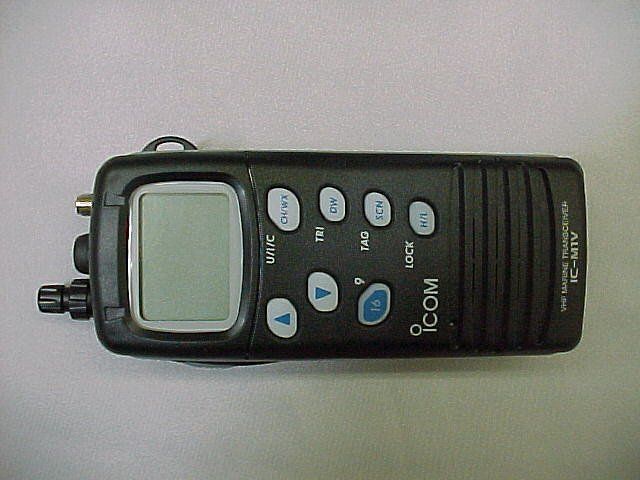
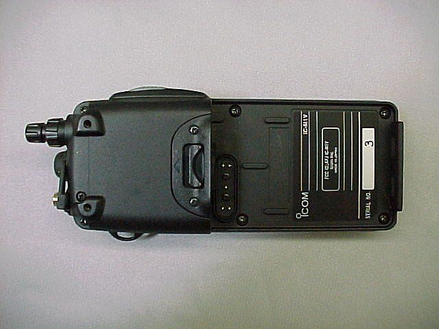
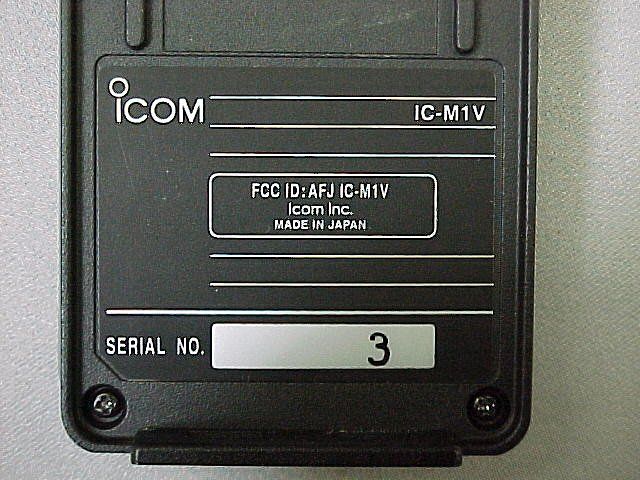
AFJIC-M1VVHF-FM Marine Hand Held Transceiver
ICOM Incorporated
Click to zoom
Application Details
- Equipment Class
- TNF - Licensed Non-Broadcast Transmitter Held to Face
- Date of Grant
- Feb 21, 2000
- Application Purpose
- Original Equipment
- Date of Application
- Nov 23, 1999
- Equipment Note
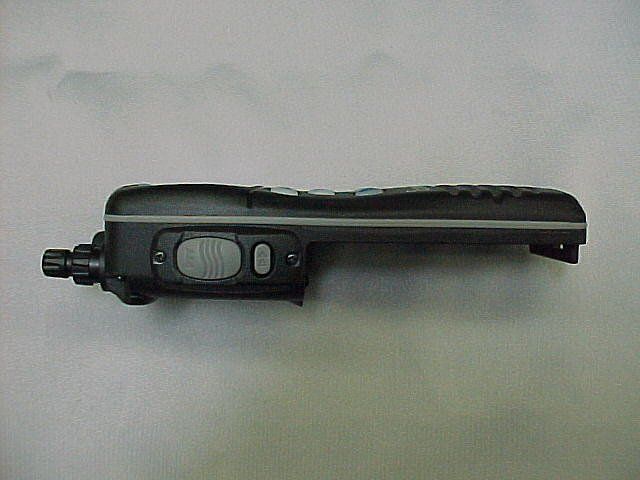
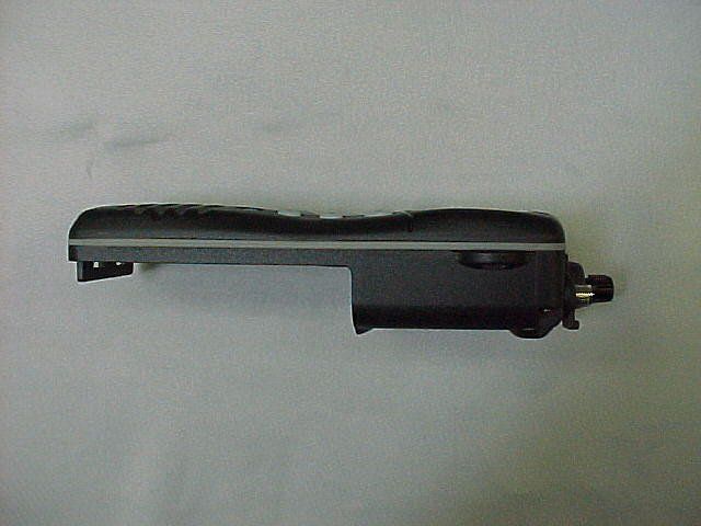
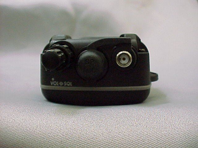
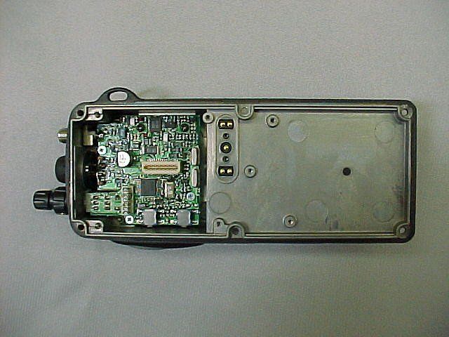
- VHF-FM Marine Hand Held Transceiver
- Frequency Range
- 156.00000000 - 157.50000000
- Company
- ICOM Incorporated
- Country
- Japan
Documents & Files
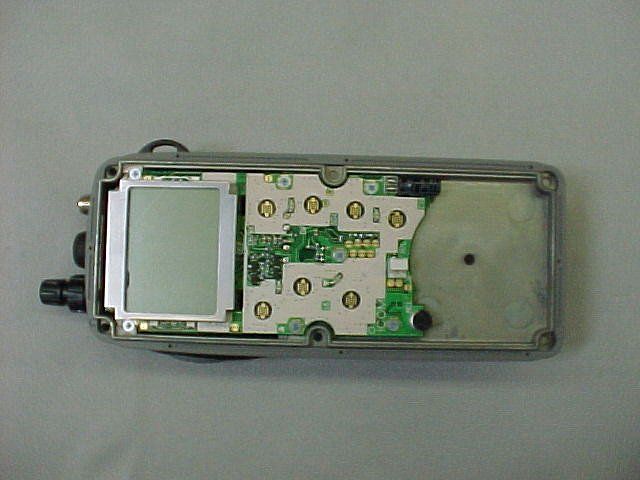
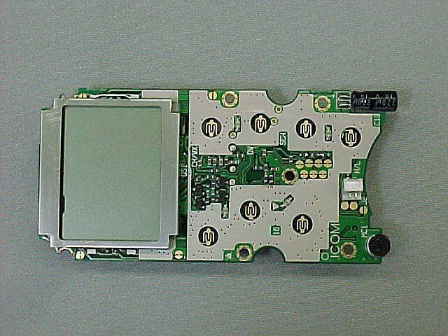
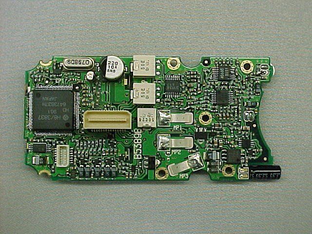
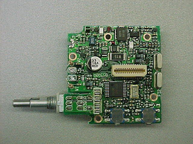
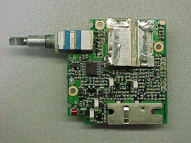
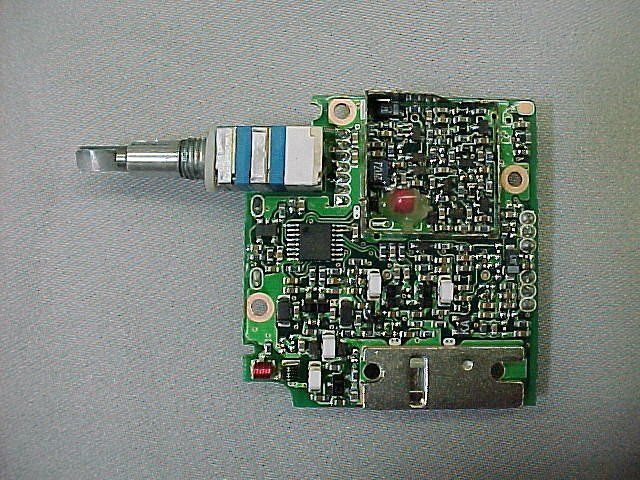
Document Text
Text extracted from the exhibit documents filed with the FCC. Open a document above to read the original.
Users Manual
INSTRUCTION MANUAL This device complies with Part 15 of the FCC rules. Operation is sub-ject to the following two conditions: (1) This device may not causeharmful interference, and (2) this device must accept any interferencereceived, including interference that may cause undesired operation. iM1VVHF MARINE TRANSCEIVER FOREWORDThank you for purchasing this Icom product. The IC-M1V VHF MARINE TRANSCEIVER is designed and built with Icom’s superi- or technology and craftsmanship. With proper care this prod-uct should provide you with years of trouble-free operation. IMPORTANTREAD ALL INSTRUCTIONS carefully and completely before using the transceiver. SAVE THIS INSTRUCTION MANUAL— This instruction manual contains important operating instructionsfor the IC-M1V. EXPLICIT DEFINITIONS CAUTIONSR WARNING! NEVER connect the transceiver to an AC outlet. This may pose a fire hazard or result in an electricshock. R WARNING! NEVER hold the transceiver so that the antenna is very close to, or touching exposed parts of thebody, especially the face or eyes, while transmitting. Thetransceiver will perform best if the microphone is 5 to 10 cm(2 to 4 in) away from the lips and the transceiver is vertical. NEVER connect the transceiver to a power source other than the BP-215. Such a connection will ruin the transceiver.NEVER charge battery packs except in the methods described in this manual. AVOID using or placing the transceiver in areas with tem- peratures below –20°C (–4°F) or above +60°C (+140°F). AVOID the use of chemical agents such as benzine or alco- hol when cleaning, as they may damage the transceiver sur-faces. After exposure to saltwater, clean the transceiver thor-oughly with fresh water to avoid corrosion. BE CAREFUL! The transceiver rear panel will become hot when operating continuously for long periods. i WORD DEFINITION R WARNING! CAUTION NOTE Personal injury, fire hazard or electric shockmay occur.Equipment damage may occur.It desired, inconvenience only. No risk ofpersonal injury, fire or electric shock. BE CAREFUL! The IC-M1V employs waterproof con- struction, which corresponds to JIS waterproof specification,grade 7 (1 m/30 min.). However, once the transceiver hasbeen dropped, it is not guaranteed due to the transceiver maybe cracked, or waterproof seal damaged, etc. MAKE SURE the flexible antenna and battery pack are securely attached to the transceiver and that the antenna andbattery pack are dry before attachment. Exposing the insideof the transceiver to water will result in serious damage to thetransceiver. KEEP the transceiver at least 1 m (3.3 ft) away from the ship’s navigation compass.KEEP the transceiver out of the reach of children. For U.S.A. onlyCAUTION: Changes or modifications to this device, not ex- pressly approved by Icom Inc., could void your authority tooperate this device under FCC regulations. IN CASE OF EMERGENCYIf your vessel requires assistance, contact other vessels andthe Coast Guard by sending a distress call on channel 16; ii m USING CHANNEL 16 DISTRESS CALL PROCEDURE1. “MAYDAY MAYDAY MAYDAY.”2. “THIS IS ....................” (name of vessel)3. Your call sign or other indication of the vessel. 4. “LOCATED AT ..........” (your position)5. The nature of the distress and assis- tance required. 6. Any other information which might facil- itate the rescue. iii TABLE OF CONTENTSFOREWORD ....................................................................... iIMPORTANT ........................................................................ iEXPLICIT DEFINITIONS ..................................................... iCAUTIONS ...................................................................... i, iiIN CASE OF EMERGENCY ............................................... iiTABLE OF CONTENTS .................................................... iii1 OPERATING RULES........................................................ 12 PANEL DESCRIPTION ............................................... 2–5 n Front panel .................................................................. 2 n Function display .......................................................... 4 3 BASIC OPERATION .................................................... 4–9 n Channel selection ........................................................ 5 n Lock function ............................................................... 6 n Adjusting the squelch level .......................................... 6 n Receiving and transmitting .......................................... 7 n Optional voice scrambler operation ............................. 8 n Call channel programming .......................................... 9 n Automatic backlighting ................................................ 9 4 DUALWATCH/TRI-WATCH ........................................... 10 n Description ................................................................ 10 n Operation .................................................................. 10 5 SCAN OPERATION ................................................. 11–12 n Scan types ................................................................. 11 n Setting tag channels .................................................. 12 n Starting a scan .......................................................... 12 6 SET MODE .............................................................. 13–14 n SET mode programming ........................................... 13 n SET mode items ........................................................ 13 7 BATTERY CHARGING ............................................ 15–16 n Battery cautions ........................................................ 15 n Battery charging ........................................................ 15 8 UNPACKING AND ACCESSORY ATTACHMENT ........ 179 TROUBLESHOOTING .................................................. 1810 CHANNEL LIST ........................................................... 1911 SPECIFICATIONS AND OPTIONS ............................…
Text truncated - open the document above for the full version.
Operational Description
IC-M1V CIRCUIT DESCRIPTION 3 - 1 1-1RECEIVER CIRCUITS 1-1-1ANTENNA SWITCHING CIRCUIT (RF UNIT) The antenna switching circuit functions as a low-pass filter while receiving and as resonator circuit while transmitting. The circuit does not allow transmit signals to enter receiver circuits. Received signals from the antenna connector pass through the low-pass fileter (L15–L17, C72–C77), and then the antenna switching circuit (D9, D11, D12). The filtered signals are then applied to the RF amplifier (Q13). 1-1-2RF AND 1ST MIXER CIRCUITS (RF UNIT) The 1st mixer circuit converts the received signals to a fixed frequency of the 1st IF signal with a PLL output frequency. By changing the PLL frequency, only the desired frequency will be passed through a pair of crystal filters at the next stage of the 1st mixer. The signals from the antenna switching circuit are passed through the tunable bandpass filter (D13, D14) and amplified at the RF amplifier (Q13). The amplified signals are passed through another tunable bandpass fileter (D15–D18), and then applied to the 1st mixer circuit (Q14). The filtered signals are mixed at the 1st mixer (Q3) with a 1st LO signal coming from the PLL circuit to produce a 21.7 MHz 1st IF signal. The 1st IF signal is passed through a pair of crystal filters (FI1,FI2) and is then amplified at the IF amplifier (Q15). 1-1-32ND IF AND DEMODULATOR CIRCUITS (MAIN AND RF UNITS) The 2nd mixer circuit converts the 1st IF signal to a 2nd IF signal. A double convertion superheterodyne system (which converts receive signal twice) improves the image rejection and obtain stable receiver gain. The 1st IF signal is applied to a 2nd mixer section of the FM IF IC (MAIN unit; IC2, pin 16). The signal is then mixed with a 2nd LO signal for conversion to a 450 kHz 2nd IF signal. IC1 contains the 2nd mixer, limiter amplifier, quadrature detector and active filter circuits. A 21.25 MHz 2nd LO signal is produced at the PLL circuit by dividing it’s reference fre- quency. The 2nd IF signal from the 2nd mixer (MAIN unit; IC1, pin 3) passes through a ceramic filter (MAIN unit; FI1 and FI2) to remove unwanted heterodyned frequencies. It is then ampli- fied at the limiter amplifier (MAIN unit; IC1, pin 5) and applied to the quadrature detector (MAIN unit; IC1, pin 10 and 11) to demodulate the 2nd IF signal into AF signals. 1-1-4AF CIRCUIT (MAIN UNIT) AF signals from the FM IF IC (IC1, pin 9) are fed to the optional voice scrambler unit to demodulate scrambled audio or are bypassed around the unit via the analog switch (IC5). The AF signals (detected signals) are passed through the analog switch (IC5, pin 8) and are then applied to the active low-pass filter (IC4, pin 9 and 10). The filtered AF signals are passed through the [VOL] control (VR unit; R1) and then another analog switch (IC3, Q3). The passed signals are applied to the AF power amplifier (IC2). 1-1-5SQUELCH CIRCUIT (MAIN UNIT) • NOISE SQUELCH The noise squelch circuit cuts out AF signals when no RF signals are received. By detecting noise components in the AF signals, the squelch circuit switches the AF mute switch. A portion of the AF signals from the FM IF IC (IC1, pin 9) are applied to the active filter section (IC1, pin 8). The active fil- ter section amplifies and filters noise components. The fil- tered signals are applied to the noise detector section and output from IC1 (pin 12) as the “SD” signal. The “SD” signal from IC2 (pin 12) is applied to the CPU (IC9, pin 98) to analyze the noise condition, and then outputs the “BEEP” signal from the CPU (IC9, pin 78) to low-pass filter (IC4, pin 10). The filtered signal is passed through the analog switch, and then applied to the AF amplifier (IC2). The amplified AF sig- nal is output to the internal speaker or the external speaker jack. • TONE SQUELCH The tone squelch circuit detects AF signals and opens the squelch only when receiving a signal containing a matching subaudible tone (CTCSS). When tone squelch is in use, and a signal with a mismatched or no subaudible tone is received, the tone squelch circuit mutes the AF signals even when noise squelch is open. A portion of the AF signals from the FM IF IC (IC1, pin 9) passes through the low-pass filter (IC4) via the analog swtich (IC5) to remove AF (voice) signals and is applied to the CTCSS decoder inside the CPU (MAIN unit; IC9, pin 97) via the “TONE” line to control the AF mute switch. 3 - 2 1-2TRANSMITTER CIRCUITS 1-2-1MICROPHONE AMPLIFIER CIRCUIT (MAIN UNIT) The microphone amplifier circuit amplifies audio signals with +6 dB/octave pre-emphasis characteristics from the micr- phone to a level needed for the modulation circuit. The AF signals from the microphone are passed through the pre-emphasis circuit (R31, C36) and are then applied to the microphone amplifier (IC4, pin 13). The amplified AF signals are applied to the optional voice scrambler unit to scramble the audio via the “MICOUT” signal, or are bypassed around the unit via an analog switch (IC5, pin 4). The amplified AF signals are amplified again at the limiter- amplifier (IC4, pin 2) and then applied to the low-pass filter (IC4, pin 6). The filtered audio is applied to the RF unit as the “MOD” signal. 1-2-2MODULATION CIRCUIT (RF UNIT) The modulation circuit modulates the VCO oscillating signal (RF signal) using the microphone audio signals. The audio signals (MOD) change the reactance of D4 to modulate an oscillated signal at the transmitter VCO (Q4, Q5). The oscillated signal is amplified at the buffer-amplifiers (Q6, Q8). 1-2-3DRIVE/POWER AMPLIFIER CIRCUITS (RF UNIT) The signal from the VCO circuit passes through the trans- mit/receive switching circuit (D7, D8) and is applied to the buffer-amplifier (Q9). The amplified signal is amplified by the pre-driver (Q10) and the power amplifier (Q11) to obtain 5W of RF power (at 7.4 V). The amplified signal passes through the antenna switching circuit (D9), and low-pass filter (C72–C77, L15–L17) and is then applied to the antenn…
Text truncated - open the document above for the full version.
Parts List/Tune Up Info
1 IC-M1V ADJUSTMENT PROCEDURES PLL LOCK VOLTAGE PLL REFERENCE FREQUENCY OUTPUT POWER FM DEVIATION 5-1 PLL AND TRANSMITTER ADJUSTMENTS Select an operating using [↑] / [↓] keys, then set specified value using [←] / [→] keys on the connected computer keyboard. 1 2 1 1 2 3 1 • Operating channel : ch 16 • Receiving • Push “Reload” bottun on the adjustment program. • Operating channel : ch 16 • Connect the RF power meter or 50 Ωdummy load to the antenna connector. • Transmitting • Push “Reload” bottun on the adjustment program. • Operating channel : ch 16 • Connect the RF power meter or 50 Ωdummy load to the antenna connector. • Transmitting • Push “Reload” bottun on the adjustment program. • Operating channel : ch 16 • [H/L] switch: High • Transmitting • Push “Reload” bottun on the adjustment program. • [H/L] switch: Low • Transmitting • Push “Reload” bottun on the adjustment program. • [H/L] switch: Extra low • Transmitting • Push “Reload” bottun on the adjustment program. • Operating channel : ch 16 • [H/L] switch: High • Connect the audio generator to the [MIC] jack and set as: 1.0 kHz/40 mV rms. • Set the FM deviation meter as: HPF: OFF LPF: 20 kHz De-emphasis : OFF Detector: (P–P)/2 • Transmitting • Push “Reload” bottun on the adjustment program. To p panel To p panel To p panel Use the adjustment program. Use the adjustment program. Loosely couple the frequnecy counter to the antenna con- nector. Connect the RF power meter to the antenna connector. Connect the FM deviation meter to the antenna con- nector through the attenuator. 2.3–3.3 V 2.3–3.3 V 156.800000 MHz 5.0 W 1.0 W 0.5 W ±4.3 kHz Verify Verify Use the adjust- ment program. Use the adjust- ment program. Use the adjust- ment program. Use the adjust- ment program. Use the adjust- ment program. ADJUSTMENTADJUSTMENT CONDITION MEASUREMENT VALUEADJUSTMENT UNITLOCATION 2 *This output level of a standard signal generator (SSG) is indicated as SSG’s open circuit. RX SENSITIVITY SQUELCH LEVEL 5-2 RECEIVER ADJUSTMENT Select an operating using [↑] / [↓] keys, then set specified value using [←] / [→] keys on the connected computer keyboard. 1 1 2 • Operating channel : ch 16 • Connect a standard signal gener- ator to the antenna connector and set as: Frequency: 156.800 MHz Level: 3.2 μV* (–97 dBm) Modulation : 1 kHz Deviation: ±3.5 kHz • Receiving • Push “Reload” bottun on the adjustment program. • Operating channel : ch 16 • No RF signals are applied to the antenna connector. • Receiving • Set the cursol to “SQL” on the adjustment program and push [ENTER] key, then push [ENTER] key again. • Operating channel : ch 16 • Connect a standard signal gener- ator to the antenna connector and set as : Level: 1.3 μV* (–105 dBm) Modulation : OFF • Receiving • Push [ENTER] key on the key- board. Use the adjustment program. Maxmum level Use the adjust- ment program. ADJUSTMENTADJUSTMENT CONDITION MEASUREMENT VALUEADJUSTMENT UNITLOCATION CONVENIENT:The BPF T1–BPF T4 can be adjusted automatically. q-1: Set the cursol to “BPF ALL” on the adjustment program and then push [ENTER] key. q-2: The connected PC tunes BPF T1–BPF T4 to peak levels. or w-1: Set the cursol to one of BPF T1, T2, T3, or T4 as desired. w-2: Push [ENTER] key to start tuning. w-3: Repeat w-1 and w-2 to perform additional BPF tuning. NOTE:Squelch level adjustment is adjusted automatically by the adjust- ment program.
Test Report
FCC ID: AFJIC-M1V MFA p99a0003, d99a0066 Date:October 14, 1999 Federal Communications Commission EQUIPMENT APPROVAL SERVICES P.O. Box 358315 Pittsburgh, PA 15251-5315 Attention:Authorization & Evaluation Division Applicant:Icom Incorporated Equipment:IC-M1V FCC ID:AFJIC-M1V FCC Rules:80 Gentlemen: On behalf of the Applicant, enclosed please find Application Form 731, Engineering Test Report and all pertinent documentation, the whole for approval of the referenced equipment as shown. Filing fees are attached. We trust the same is in order. Should you need any further information, kindly contact the writer who is authorized to act as agent. Sincerely yours, William H. Graff, Director of Engineering enclosure(s) ELECTRONIC FILING cc: Applicant WHG/cvr FCC ID: AFJIC-M1V MFA p99a0003, d99a0066 LIST OF EXHIBITS (FCC CERTIFICATION (TRANSMITTERS) - REVISED 9/28/98) APPLICANT:Icom Incorporated FCC ID:AFJIC-M1V BY APPLICANT: 1. LETTER OF AUTHORIZATION 2. IDENTIFICATION DRAWINGS, 2.1033(c)(11) LABEL LOCATION OF LABEL COMPLIANCE STATEMENT LOCATION OF COMPLIANCE STATEMENT 3. PHOTOGRAPHS, 2.1033(c)(12) 4. DOCUMENTATION: 2.1033(c) (3)USER MANUAL (9)TUNE-UP/ALIGNMENT PROCEDURE (10)SCHEMATIC DIAGRAM (10) OPERATIONAL DESCRIPTION 5. PART 80 ATTESTATION BY M.F.A. INC. A.TESTIMONIAL & STATEMENT OF CERTIFICATION B.STATEMENT OF QUALIFICATIONS FCC ID: AFJIC-M1V MFA p99a0003, d99a0066 Sub-part 2.1033(c): EQUIPMENT IDENTIFICATION FCC ID: AFJIC-M1V NAMEPLATE DRAWING ATTACHED, EXHIBIT 1. LOCATION AS PER LABEL DRAWING(S) DATE OF REPORT October 14, 1999 SUPERVISED BY:William H. Graff, Director of Engineering FCC ID: AFJIC-M1V MFA p99a0003, d99a0066 THE APPLICANT HAS BEEN CAUTIONED AS TO THE FOLLOWING: 15.21INFORMATION TO USER. The users manual or instruction manual for an intentional radiator shall caution the user that changes or modifications not expressly approved by the party responsible for compliance could void the user's authority to operate the equipment. 15.27(a)SPECIAL ACCESSORIES. Equipment marketed to a consumer must be capable of complying with the necessary regulations in the configuration in which the equipment is marketed. Where special accessories, such as shielded cables and/or special connectors are required to enable an unintentional or intentional radiator to comply with the emission limits in this part, the equipment must be marketed with, i.e. shipped and sold with, those special accessories. However, in lieu of shipping or packaging the special accessories with the unintentional or intentional radiator, the responsible party may employ other methods of ensuring that the special accessories are provided to the consumer, without additional charge. Information detailing any alternative method used to supply the special accessories for a grant of equipment authorization or retained in the verification records, as appropriate. The party responsible for the equipment, as detailed in § 2.909 of this chapter, shall ensure that these special accessories are provided with the equipment. The instruction manual for such devices shall include appropriate instructions on the first page of text concerned with the installation of the device that these special accessories must be used with the device. It is the responsibility of the user to use the needed special accessories supplied with the equipment. FCC ID: AFJIC-M1V MFA p99a0003, d99a0066 TABLE OF CONTENTS RULEDESCRIPTIONPAGE .Test Report1 2.1033(c)General Information Required2 2.1033(c)(14) Rule Summary5 .Standard Test Conditions and Engineering Practices6 2.1046(a) P.F. Power Output7 2.1047(a) Audio Frequency Response9 2.1047(a) Audio Low Pass Filter (Voice Input)12 2.1047(b) Modulation Limiting14 2.1049(c)(1) Emission Masks (Occupied Bandwidth)16 2.1051 Spurious Emissions at Antenna Terminals)21 2.1053(a) Field Strength of Spurious Radiation23 2.1055(a)(1) Frequency Stability (Temperature Variation)27 2.1055(b)(1)Frequency Stability (Voltage Variation)30 2.202(g) Necessary Bandwidth and Emission Bandwidth39 FCC ID: AFJIC-M1V MFA p99a0003, d99a0066 PAGE NO.1 of 39. Required information per ISO/IEC Guide 25-1990, paragraph 13.2: a)TEST REPORT b) Laboratory: (FCC: 31040/SIT) (Canada: IC 2044) M. Flom Associates, Inc. 3356 N. San Marcos Place, Suite 107 Chandler, AZ 85225 c) Report Number:d99a0066 d) Client:Icom America, Inc. 2380 - 116th Ave. N. E. P.O. C-90029 Bellevue, Washington 98009-9029 e) Identification:IC-M1V FCC ID: AFJIC-M1V Description:VHF Marine Transceiver f) EUT Condition:Not required unless specified in individual tests. g) Report Date:October 14, 1999 EUT Received:October 6, 1999 h, j, k):As indicated in individual tests. i) Sampling method:No sampling procedure used. l) Uncertainty:In accordance with MFA internal quality manual. m) Supervised by: William H. Graff, Director of Engineering n) Results:The results presented in this report relate only to the item tested. o) Reproduction: This report must not be reproduced, except in full, without written permission from this laboratory. FCC ID: AFJIC-M1V MFA p99a0003, d99a0066 PAGE NO.2 of 39. LIST OF GENERAL INFORMATION REQUIRED FOR CERTIFICATION IN ACCORDANCE WITH FCC RULES AND REGULATIONS, VOLUME II, PART 2 AND TO 80 Sub-part 2.1033 (c)(1):NAME AND ADDRESS OF APPLICANT: Icom Incorporated 1-6-19 Kamikurazukuri Hirano-ku Osaka, Japan 547 MANUFACTURER: Applicant (c)(2):FCC ID:AFJIC-M1V MODEL NO:IC-M1V (c)(3):INSTRUCTION MANUAL(S): PLEASE SEE ATTACHED EXHIBITS (c)(4):TYPE OF EMISSION:16K0G3E (c)(5):FREQUENCY RANGE, MHz:156 to 157.5 (c)(6):POWER RATING, Watts: 0.5 to 1 to 5 xSwitchableVariableN/A (c)(7):MAXIMUM POWER RATING, Watts:25 25 FCC ID: AFJIC-M1V MFA p99a0003, d99a0066 PAGE NO.3 of 39. Subpart 2.1033 (continued) (c)(8):VOLTAGES & CURRENTS IN ALL ELEMENTS IN FINAL R. F. STAGE, INCLUDING FINAL TRANSISTOR OR SOLID STATE DEVICE: COLLECTOR CURRENT, A=per manual COLLECTOR VOLTAGE, Vdc=per manual SUPPLY VOLTAGE, Vdc=7.4 (c)(9):TUNE-UP PROCEDURE: PLEASE SEE ATTACHED EXHIBITS (c)(10):CIRCUIT DIAG…
Text truncated - open the document above for the full version.
Contact Information
Applicant
Atsushi Tomiyama(General Manager)
Technical Contact
M. Flom Associates, Inc.William H Graff
[email protected]480 926 3100
3356 N. San Marcos Place · Chandler, Arizona · United States
Non-Technical Contact
M. Flom Associates, Inc.William H Graff
[email protected]480 926 3100
Test Firm
M. Flom Associates, Inc.Morton Flom
Technical Specifications
| # | Rule Parts | Frequency Range | Power Output | Emission | Tolerance |
|---|---|---|---|---|---|
| 6 | 8 | 156 MHz - 157.5 MHz | 500.00 mW | 16K0G3W | 10 ppm |
Other Applications from ICOM Incorporated

AFJ453700
Jul 23, 2026Mobile Transceiver
Equipment Class
DTS - Digital Transmission System
AFJ452000
Jun 02, 2026VHF DIGITAL TRANSCEIVER
Equipment Class
TNF - Licensed Non-Broadcast Transmitter Held to Face
AFJ452100
May 12, 2026UHF DIGITAL TRANSCEIVER
Equipment Class
TNF - Licensed Non-Broadcast Transmitter Held to Face
AFJ444500
Sep 12, 2024Scanning Receiver
Equipment Class
CSR - Scanning Receiver
AFJ410900
Jul 09, 2024Linear Amplifier
Equipment Class
AMP - Amplifier