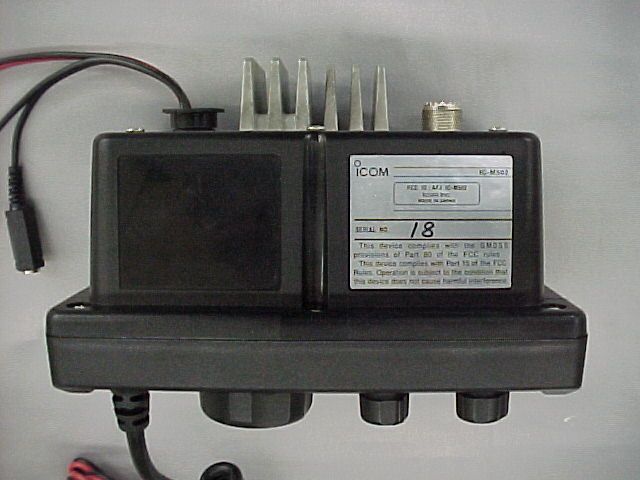
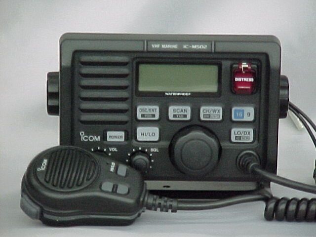
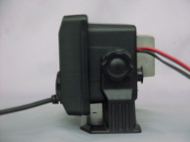
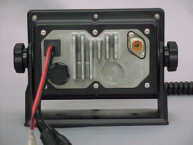
AFJIC-M502Mobile Marine Transceiver
ICOM Incorporated
Click to zoom
Application Details
- Equipment Class
- TNB - Licensed Non-Broadcast Station Transmitter
- Date of Grant
- Jul 16, 2000
- Application Purpose
- Original Equipment
- Date of Application
- May 11, 2000
- Equipment Note
- Mobile Marine Transceiver
- Frequency Range
- 156.00000000 - 163.00000000
- Company
- ICOM Incorporated
- Country
- Japan
Documents & Files
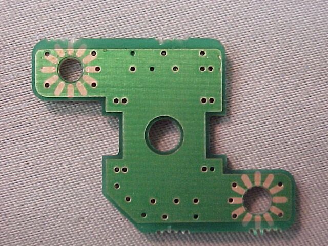
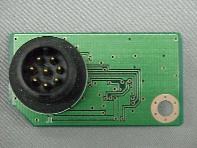
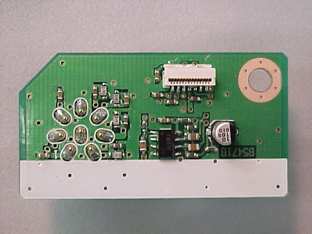
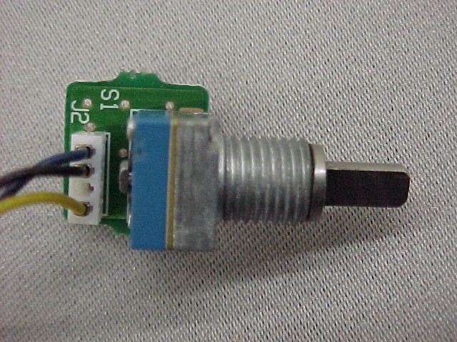
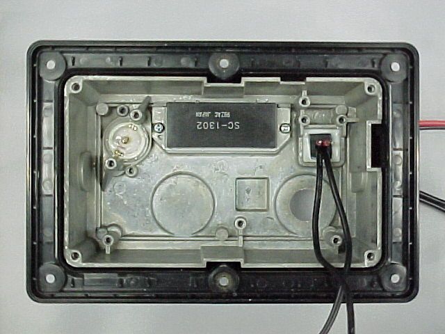
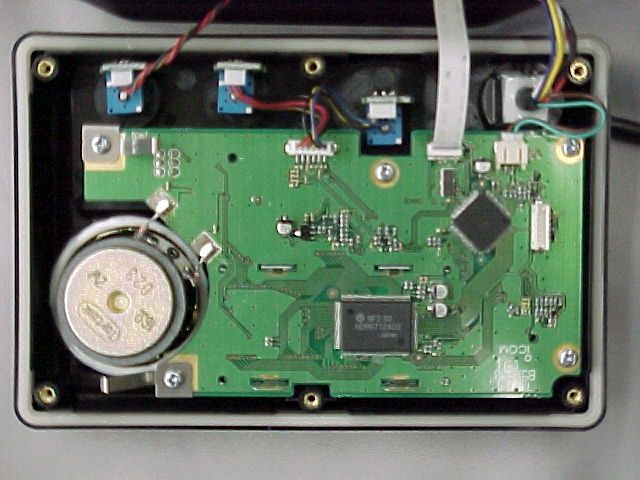
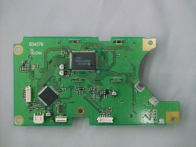
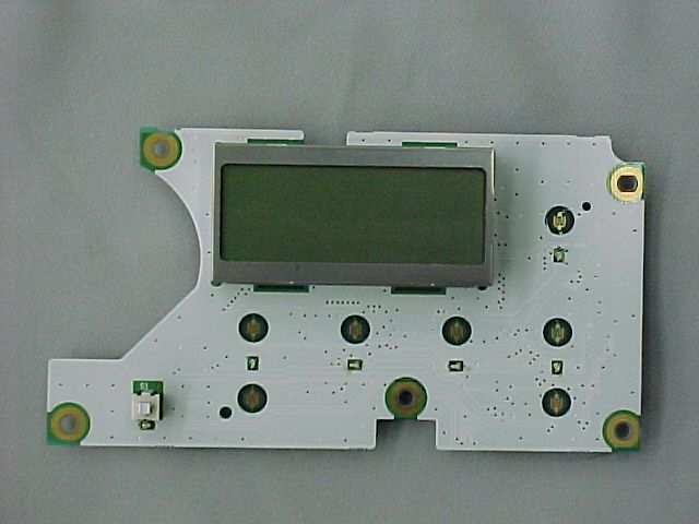
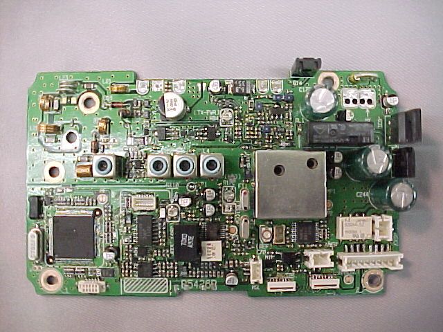
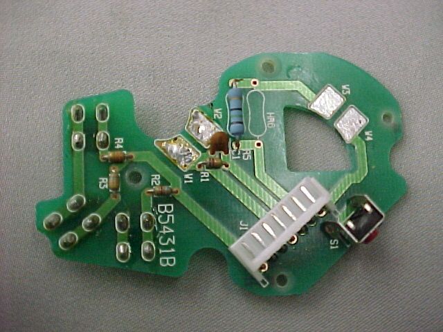
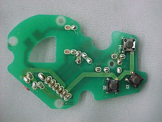
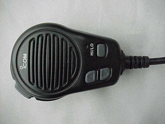
Document Text
Text extracted from the exhibit documents filed with the FCC. Open a document above to read the original.
Users Manual
IC-M501 - 1 - IC-M502 Operational Manual Table of contents 1. Front panel layout 2. Rear Panel 3. Radio operation I Display Ii Readout and operation III DSC operation Iv User set mode IC-M501 - 2 - 1. Front panel 1. Front panel1. Front panel 1. Front panel USA Model USA ModelUSA Model USA Model 16 9 VOL LO/DX IC DSC/ENT POS SCAN TAG HI/LOW DIMMER SQL DISTRESS SP CH/WX DW U/I/C SEL POWER IC-M501 - 3 - Name Operation Silk Print Function and Operation Repress once 16 Recall CH16 Holding for one sec. 9 Recall CH9 or reprogramming CALL CH when CH 9 is selected 16 Repress 16 with holding HI/LOW button Editing CH name Repress once CH/WX Toggle between user CH and WX Holding for 1sec. DW Start/Stop Dual or tri watch CH/WX Repress CH/WX with holding HI/LOW button U/I/C Selecting USA, INT or CANADA mode Repress once SCAN Start/Stop normal or priority scan Holding for 1sec. TAG Tag or un-tag channel for scanning SCAN Repress SCAN with holding HI/LOW button Clear all tagged channel with holding those buttons Repress once HI/LOW Switch output power between 25W and 1W Holding for 1sec. No function HI/LOW With Holding HI/LOW button No function Repress once DSC/ENT Selecting DSC call menu and selection Holding for 1sec. POS Display LAT/LON and time DSC/ENT Repress DSC with holding HI/LOW button No function Repress once LO/DX Turning on/off ATT on receiver Holding for 1sec. IC Turning on/off intercom LO/DX Repress LO/DX with holding HI/LOW button Turning on/off scrambler Repress once No function Holding for 5 sec. DISTRESS Transmitting distress signals DISTRESS Repress DISTRESS with holding HI/LOW button No function Turning knob Selecting CH SELECTOR Turing Dial knob with holding HI/LOW button Adjusting dimmer POWER Repress POWER Turning on /off the radio VOLUME Turing knob VOL Adjusting receive audio SQUELCH Turning knob SQL Adjusting SQL Turning on the radio with holding CH 16 will select radio setup mode IC-M501 - 4 - Europe Model Europe ModelEurope Model Europe Model CALL VOL DIMMER DUAL SCAN TAG HI/LOW SQL 16 SP DIAL SEL POWER IC-M501 - 5 - Name Operation Silk Print Function and Operation Repress once CALL Recall CALL CH Holding for one sec. Reprogramming CALL CH CALL Repress CALL with holding HI/LOW button Editing CH name Repress once DIAL Switching to user CH mode Holding for 1sec. No function DIAL Repress DIAL with holding HI/LOW button Selecting USA, INT mode Repress once SCAN Start/Stop normal or priority scan Holding for 1sec. TAG Tag or un-tag channel for scanning SCAN Repress SCAN with holding HI/LOW button Clear all tagged channel with holding those buttons Repress once HI/LOW Switch output power between 25W and 1W Holding for 1sec. No function HI/LOW With Holding HI/LOW button No function Repress once DUAL Start/Stop dual or tri watch Holding for 1sec. No function DUAL Repress DUAL with holding HI/LOW button No function Repress once DIMMER Selecting Dimmer level Holding for 1sec. DIMMER No function DIMMER Repress DIMMER with holding HI/LOW button Turning on/off scrambler Repress once 16 Recall CH16 Holding for 1 sec. No function 16 Repress DISTRESS with holding HI/LOW button No function Turning knob Selecting CH SELECTOR Turing Dial knob with holding HI/LOW button No function POWER Repress POWER Turning on /off the radio VOLUME Turing knob VOL Adjusting receive audio SQUELCH Turning knob SQL Adjusting SQL Turning on the radio with holding CH 16 will select radio setup mode IC-M501 - 6 - 2.Rear Pan 2.Rear Pan2.Rear Pan 2.Rear Panel elel el USA Model USA ModelUSA Model USA Model 1. NMEA input jack (Pig Tail) 2. Speaker output jack (Pig Tail) 3. Socket for remote control unit 4. DC power cable (Pig Tail) Europe Model Europe ModelEurope Model Europe Model 1. Speaker output jack (Pig Tail) 2. Socket for DS-100 (DSC unit) 3. DC power cable (Pig Tail) IC-M501 - 7 - 3. 3.3. 3. Radio Operation Radio Operation Radio Operation Radio Operation i.. Display Following words are showing on display TX Transmit indicator TAG Tagged CH indicator BUSY The BUSY indicator shows radio has incoming receive signals SCAN Blinks during scanning RF output power indicator DUAL WATCH Blinks during dual watch CALL Call channel indicator TRI- WACH Blinks during tri watch CAN DUP Shows duplex channel USA SC Scrambler indicator INT LOCAL Receive ATT on WX Low Battery It shows DC voltage is less than 10 V Mode display CH display 7seg It shows current selected CH ALERT WX alert display SP OFF Internal speaker is off IC-M501 - 8 - Ii Display and operation 1. Transmit and receive readout 09 CH16 is selected 20 RX with SQL close 20 RX with SQL open 16 20 TX with high power 20 TX with low power CALL CH is selected IC-M501 - 9 - 2 Operation mode readout Repressing CH/WX button while holding HI/LOW button 3 DUAL / TRI watch Radio setup mode selects DUAL or TRI watch 4 Scan The radio comes with four different scanning modes, Normal scan, Normal scan with WX alert, Priority scan and Priority scan with WX alert, and you may select them from setup mode When you repressed UP or DOWN button, the radio will pause scan If you repress UP or DOWN button again, the radio will display tagged channels, then the radio will resume scanning 20 20 20 20 20 IC-M501 - 10 - During pausing scan, holding SCAN button for 1 sec. will un-tag the channel, and will resume scanning 5 WX channel 6 LAT/LON display Holding DSC/ENT button for 1 sec will display position Repressing other button will cancel this mode 20 10 10 20 20 20 GPS connected ’ ’ 20 Position error from GPS No GPS receiver is connected Blinks IC-M501 - 11 - 7 Internal Speaker off…
Text truncated - open the document above for the full version.
Operational Description
1 RECEIVER CIRCUITS 1-1 ANTENNA SWITCHING CIRCUIT The antenna switching circuit functions as a low-pass filter while receiving and as resonator circuit while transmitting. The circuit does not allow transmit signals to enter receiver circuits. Received signals enter the MAIN unit from the antenna connector and pass through the low-pass filter (L23–L25, C134, C136–C139). The signals are then applied to the RF circuit via the antenna switching circuit (D17, L26, L27, C141–C143). 1-2 RF CIRCUIT The RF circuit amplifies signals within the range of frequency coverage and filters out-of-band signals. The signals from the antenna switching circuit pass through a tunable bandpass filter (D1, L1. C2–C4) where the object signals are led to the RF amplifier circuit (Q2). The amplified signals at Q2 are applied to the 3-stage tunable bandpass filter (D2–D4, L2–L4, C13, C14, C16–C18, C20–C24) to suppress unwanted signals and improve the selectivity. The signals are then applied to the 1st mixer circuit. D1–D4 employ varactor diodes, that are controlled by the PLL lock voltage, to track the band pass filters. 1-3 1ST MIXER AND 1ST IF CIRCUITS The 1st mixer circuit converts the received signal to a fixed frequency of the 1st IF signal with a 1st LO (VCO output) frequency. By changing the 1st LO frequency, only the desired frequency will pass through a pair of crystal filters at the next stage of the mixer. The signals from the RF circuit are mixed with the VCO signals at the 1st mixer circuit (Q3) to produce a 21.7 MHz 1st IF signal. The 1st IF signal is applied to a pair of crystal filters (FI1, FI2) to suppress out-of-band signals and is then amplified at the IF amplifier (Q4). The amplified signal is applied to the 2nd mixer circuit (IC1). 1-4 2ND IF AND DEMODULATOR CIRCUITS The 2nd mixer circuit converts the 1st IF signal to a 2nd IF signal. A double superheterodyne system (which converts receive signals twice) improves the image rejection ratio and obtains stable receiver gain. The FM IF IC (IC1) contains the 2nd local oscillator, 2nd mixer, limiter amplifier, quadrature detector, and noise detector circuits, etc. The 1st IF signal from Q4 is applied to the 2nd mixer section of IC1 (pin 16), and is mixed with a 21.25 MHz 2nd LO signal generated at the PLL circuit using the reference frequency (21.25 MHz) to produce a 450 kHz 2nd IF signal. The 2nd IF signal from IC1 (pin 3) is passed through the ceramic filter (FI3), where unwanted signals are suppressed, and is then applied to the 2nd IF (limiter) amplifier in IC1 (pin 5). The signal is applied to the FM detector section in IC1 for demodulation into AF signals. The FM detector circuit employs a quadrature detection method (linear phase detection), which uses a ceramic discriminator (X1) for phase delay to obtain a non-adjusting circuit. The detected signal from IC1 (pin 9) is applied to the AF circuit. 1-5 AF AMPLIFIER CIRCUIT The AF amplifier circuit amplifies the detected signals to drive a speaker. The AF circuit includes an AF mute circuit for the squelch. AF signals from IC1 (pin 9) are applied to the de-emphasis circuit (R118, C182). The de-emphasis circuit is an integrated circuit with frequency characteristic of –6 dB/octave. The integrated signals are applied to the active filters (Q24, Q25) via the analog switch (IC12, pins 10, 11). Q24 functions as a high-pass filter to suppress unwanted lower noise signals and Q25 functions as a low-pass filter to suppress higher noise signals. The filtered signals are passed through the [VOLUME] control, and are then applied to the AF power amplifier (IC14, pin 1). The output signal from IC14 (pin 4) drives the internal (external) speaker. 1-6 SQUELCH CIRCUIT A squelch circuit cuts out AF signals when no RF signals are received. By detecting noise components in the AF signals, the squelch circuit switches the AF mute switch. A portion of the AF signals from the FM IF IC (IC1, pin 9) pass through the [SQUELCH] control pot (R33), and are then applied to the active filter section (IC1, pin 8). The active filter section amplifies and filters noise components. The filtered signals are applied to the noise detector section and output from pin 14 as the “SQLI” signal. The “SQLI” signal is amplified at the DC amplifier (IC20) and applied to the CPU (IC16, pin 39) as the “SQL” signal. The CPU analyzes the noise condition and outputs the “RMUTM”, “RMUTS” signals to toggle the AF mute switches (Q26, Q27). 2 TRANSMITTER CIRCUITS 2-1 MICROPHONE AMPLIFIER CIRCUIT The microphone amplifier circuit amplifies audio signals with +6 dB/octave pre-emphasis from the microphone to a level needed at the modulation circuit. The AF signals from the microphone are amplified at the microphone amplifier (IC11a) via the analog switch (IC10, pins 11, 10). A capacitor (C214) and resistor (R147) are connected to the amplifier to obtain the pre-emphasis characteristics. The amplified signals are applied to the IDC amplifier (IC13a, pin 2) via the analog switch (IC12, pins 8, 9 and pins 4, 3) and are passed through the splatter filter (IC13b) to suppress unwanted 3 kHz or higher signals. The filtered signals are then applied to the modulation circuit. 2-2 MODULATION CIRCUIT The modulation circuit modulates the VCO oscillating signal (RF signal) using the microphone audio signals. Audio signals from the splatter filter (IC13b) pass through the frequency deviation adjustment pot (R172) and are then applied to the modulation circuit (D8) to change the reactance of D8, and modulate the oscillated signal at the TX-VCO (Q7). 2-3 DRIVE AMPLIFIER CIRCUIT The drive amplifier circuit amplifies the VCO oscillating signal to a level needed at the power amplifier. The VCO output is buffer-amplified by Q9 and Q10, and is then applied to the Tx/Rx switch (D12). The transmit signal from the Tx/Rx switch is amplified to the pre-drive (Q11) and drive (Q12) amplifiers to obtain an approximate 200 mW signal level. The amplified signal is then applied to …
Text truncated - open the document above for the full version.
Parts List/Tune Up Info
IC-M502 Alignment Procedure PLL lock voltage - Connect multi-meter between CP1 and ground - Apply 13.8V to DC connector on radio, and turns radio on - Select CH16, and receive - Adjust L13 for 2.5V - Transmit - Adjust L10 for 2.5V Transmitter - Connect RF power meter to ANT connector - Apply 13.8V to DC connector on radio, and turns radio on - Select CH16, and high power setting - Transmit - Adjust R84 for 26W PLL Reference crystal - Connect 50 ohms dummy load to ANT connector - Apply 13.8V to DC connector on radio, and turns radio on - Loosely couples probe on frequency counter - Select CH16 - Transmit - Adjust C70 for 156.8000MHz Transmit Modulation - Connect transmit modulation analyzer to ANT connector - Connect audio generator to mic terminal - Apply 13.8V to DC connector on radio, and turns radio on - Apply 1Khz/150mV signals to mic terminal - Select CH16, and high power setting - Transmit - Adjust R172 for 4.3KHz - Adjust audio signal generator for 3.5Kz deviation - Verify audio output signals is between 10mV and 21mV - Verify signal to noise ratio for better than 40dB Transmit Sprious - Connect spectrum analyzer to ANT connector - Apply 13.8V to DC connector on radio, and turns radio on - Select CH16, and high power setting - Transmit - Verify the harmonic for better than –70dB Receiver - Connect RF signal generator to ANT connector - Connect AC voltmeter with 4 ohm load to speaker jack - Apply 13.8V to DC connector on radio, and turns radio on - Select CH16 - Apply 156.800MHz with 1KHz/3,5KHz deviation / -96dBm signal to ANT connector - Receive - Adjust L1, L2, L3 and L4 for maximum voltage - Verify receive sensitivity is –117dBm or better SQL - Connect RF signal generator to ANT connector - Connect DC volt meter to CP5 - Apply 13.8V to DC connector on radio, and turns radio on - Select CH16 - Apply 156.800MHz with 1KHz/3,5KHz deviation / -122dBm signal to ANT connector - Receive - Adjust R33 for 2V
Test Report
FCC ID: AFJIC-M502 MFA p0050003, d0050026 Date: May 12, 2000 Federal Communications Commission Via Electronic Filing Attention: Authorization & Evaluation Division Applicant: Icom Incorporated Equipment: IC-M502 FCC ID: AFJIC-M502 FCC Rules: 80 Gentlemen: On behalf of the Applicant, enclosed please find Application Form 731, Engineering Test Report and all pertinent documentation, the whole for approval of the referenced equipment as shown. Filing fees are attached. We trust the same is in order. Should you need any further information, kindly contact the writer who is authorized to act as agent. Sincerely yours, Morton Flom, P. Eng. enclosure(s) cc: Applicant MF/cvr FCC ID: AFJIC-M502 MFA p0050003, d0050026 LIST OF EXHIBITS (FCCCERTIFICATION(TRANSMITTERS) - REVISED 9/28/98) APPLICANT: Icom Incorporated FCC ID: AFJIC-M502 BY APPLICANT: 1. LETTER OF AUTHORIZATION 2. IDENTIFICATION DRAWINGS, 2.1033(c)(11) LABEL LOCATION OF LABEL COMPLIANCE STATEMENT LOCATION OF COMPLIANCE STATEMENT 3. PHOTOGRAPHS, 2.1033(c)(12) 4. DOCUMENTATION: 2.1033(c) (3) USER MANUAL (9) TUNE-UP/ALIGNMENT PROCEDURE (10) SCHEMATIC DIAGRAM (10) OPERATIONAL DESCRIPTION BLOCK DIAGRAM PARTS LIST ACTIVE DEVICES 5. PART 90.203(e) & (g) ATTESTATION BY M.F.A. INC. A. TESTIMONIAL & STATEMENT OF CERTIFICATION B. STATEMENT OF QUALIFICATIONS FCC ID: AFJIC-M502 MFA p0050003, d0050026 Sub-part 2.1033(c): EQUIPMENT IDENTIFICATION FCC ID: AFJIC-M502 NAMEPLATE DRAWING ATTACHED, EXHIBIT 1. LOCATION AS PER LABEL DRAWING(S) DATE OF REPORT May 12, 2000 SUPERVISED BY: Morton Flom, P. Eng. FCC ID: AFJIC-M502 MFA p0050003, d0050026 THE APPLICANT HAS BEEN CAUTIONED AS TO THE FOLLOWING: 15.21 INFORMATION TO USER. The users manual or instruction manual for an intentional radiator shall caution the user that changes or modifications not expressly approved by the party responsible for compliance could void the user's authority to operate the equipment. 15.27(a) SPECIAL ACCESSORIES. Equipment marketed to a consumer must be capable of complying with the necessary regulations in the configuration in which the equipment is marketed. Where special accessories, such as shielded cables and/or special connectors are required to enable an unintentional or intentional radiator to comply with the emission limits in this part, the equipment must be marketed with, i.e. shipped and sold with, those special accessories. However, in lieu of shipping or packaging the special accessories with the unintentional or intentional radiator, the responsible party may employ other methods of ensuring that the special accessories are provided to the consumer, without additional charge. Information detailing any alternative method used to supply the special accessories for a grant of equipment authorization or retained in the verification records, as appropriate. The party responsible for the equipment, as detailed in § 2.909 of this chapter, shall ensure that these special accessories are provided with the equipment. The instruction manual for such devices shall include appropriate instructions on the first page of text concerned with the installation of the device that these special accessories must be used with the device. It is the responsibility of the user to use the needed special accessories supplied with the equipment. FCC ID: AFJIC-M502 MFA p0050003, d0050026 TABLE OF CONTENTS RULE DESCRIPTION PAGE . Test Report 1 2.1033(c) General Information Required 2 2.1033(c)(14) Rule Summary 5 . Standard Test Conditions and Engineering Practices 6 80.365 VHF Radiotelephone Frequencies 7 2.1046(a) P.F. Power Output 8 2.1047(a) Audio Frequency Response 10 2.1047(a) Audio Low Pass Filter (Voice Input) 13 2.1047(b) Modulation Limiting 15 2.1049(c)(1) Emission Masks (Occupied Bandwidth) 17 2.1051 Spurious Emissions at Antenna Terminals) 22 2.1053(a) Field Strength of Spurious Radiation 25 2.1055(a)(1) Frequency Stability (Temperature Variation) 29 2.1055(b)(1) Frequency Stability (Voltage Variation) 32 80.203(b) User Controls 33 80.959(c)(1)(2)&(3) Power Output Over Time 34 80.959(a)&(b) Subpart T – G3E Emissions 37 80.956(a)&(b) Subpart T – G3E Emissions 38 80.961(a)&(b) Subpart T – G3E Emissions 39 80.1011, 80.1013 Subpart U – Bridge-to-Bridge Act 40 2.202(g) Necessary Bandwidth and Emission Bandwidth 41 FCC ID: AFJIC-M502 MFA p0050003, d0050026 PAGE NO.1of41. Required information per ISO/IEC Guide 25-1990, paragraph 13.2: a) TEST REPORT b) Laboratory: (FCC: 31040/SIT) (Canada: IC 2044) M. Flom Associates, Inc. 3356 N. San Marcos Place, Suite 107 Chandler, AZ 85225 c) Report Number:d0050026 d) Client: Icom America, Inc. 2380 - 116th Ave. N. E. P.O. C-90029 Bellevue, Washington 98009-9029 e) Identification: IC-M502 FCC ID: AFJIC-M502 Description: VHF Marine Transceiver f) EUT Condition: Not required unless specified in individual tests. g) Report Date: May 12, 2000 EUT Received: May 4, 2000 h, j, k): As indicated in individual tests. i) Sampling method: No sampling procedure used. l) Uncertainty: In accordance with MFA internal quality manual. m) Supervised by: Morton Flom, P. Eng. n) Results: The results presented in this report relate only to the item tested. o) Reproduction: This report must not be reproduced, except in full, without written permission from this laboratory. FCC ID: AFJIC-M502 MFA p0050003, d0050026 PAGE NO.2of41. LIST OF GENERAL INFORMATION REQUIRED FOR CERTIFICATION IN ACCORDANCE WITH FCC RULES AND REGULATIONS, VOLUME II, PART 2 AND TO 80 Sub-part 2.1033 (c)(1): NAME AND ADDRESS OF APPLICANT: Icom Incorporated 1-6-19 Kamikurazukuri Hirano-ku Osaka, Japan 547 MANUFACTURER: Icom Incorporated 6-9-16 Kamihigashi Hirano-Ku Osaka, Japan 547 (c)(2): FCC ID: AFJIC-M502 MODEL NO: IC-M502 (c)(3): INSTRUCTION MANUAL(S): PLEASE SEE ATTACHED EXHIBITS (c)(4): TYPE OF EMISSION: 16K0G3E (c)(5): FREQUENCY RANGE, MHz : 156 to 163 (c)(6): POWER RATING, Watts:1,25 x Switchable Variable N/A FCC GRANT NOTE: OW – meets requirements of Section 80.80(a0(4) (c)(7): MAXIMUM POWER RATING…
Text truncated - open the document above for the full version.
Contact Information
Applicant
Atsushi Tomiyama(General Manager)
Technical Contact
M. Flom Associates, Inc.Morton Flom
[email protected]480 926 3100
3356 N. San Marcos Pl., Suite 107 · Chandler, Arizona · United States
Non-Technical Contact
M. Flom Associates, Inc.Morton Flom
[email protected]480 926 3100
Test Firm
M. Flom Associates, Inc.Morton Flom
Technical Specifications
| # | Rule Parts | Frequency Range | Power Output | Emission | Tolerance |
|---|---|---|---|---|---|
| 2 | 8 | 156 MHz - 163 MHz | 25 W | 16K0F3E | 5 ppm |
Other Applications from ICOM Incorporated

AFJ453700
Jul 23, 2026Mobile Transceiver
Equipment Class
DTS - Digital Transmission System
AFJ452000
Jun 02, 2026VHF DIGITAL TRANSCEIVER
Equipment Class
TNF - Licensed Non-Broadcast Transmitter Held to Face
AFJ452100
May 12, 2026UHF DIGITAL TRANSCEIVER
Equipment Class
TNF - Licensed Non-Broadcast Transmitter Held to Face
AFJ444500
Sep 12, 2024Scanning Receiver
Equipment Class
CSR - Scanning Receiver
AFJ410900
Jul 09, 2024Linear Amplifier
Equipment Class
AMP - Amplifier