AFJIC-T90AAmateur Transceiver with Scanning Receiver
ICOM Incorporated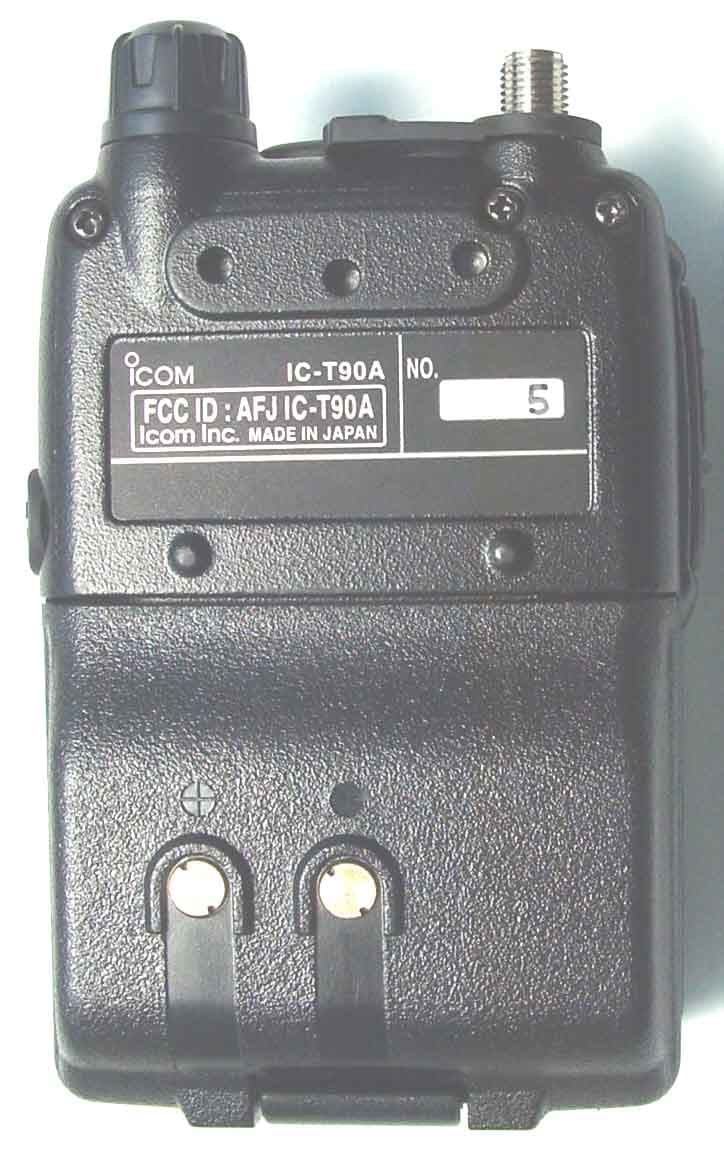
Click to zoom
Application Details
- Equipment Class
- CSR - Scanning Receiver
- Date of Grant
- Jul 20, 2002
- Application Purpose
- Original Equipment
- Date of Application
- Jul 20, 2002
- Equipment Note
- Amateur Transceiver with Scanning Receiver
- Frequency Range
- 928.00000000 - 999.99000000
- Company
- ICOM Incorporated
- Country
- Japan
Documents & Files
Document Text
Text extracted from the exhibit documents filed with the FCC. Open a document above to read the original.
Users Manual
This device complies with Part 15 of the FCC Rules. Operation is sub-ject to the following two conditions: (1) This device may not causeharmful interference, and (2) this device must accept any interferencereceived, including interference that may cause undesired operation. iT90A MULTIBAND FM TRANSCEIVER INSTRUCTION MANUAL WARNING: MODIFICATION OF THIS DEVICE TO RECEIVE CEL- LULAR RADIO TELEPHONE SERVICE SIGNALS IS PROHIBITEDUNDER FCC RULES AND FEDERAL LAW. IC-T90A_IM.qxd 02.5.28 01:12 PM Page a (1,1) FOREWORD i Thank you for purchasing this Icom product. The IC-T90AMULTIBAND TRANSCEIVER is designed and built withIcom’s superior technology and craftsmanship. With propercare, this product should provide you with years of trouble-free operation.The IC-T90A is a tri-band, 6 m, 2 m (140 MHz), 440 MHz FMtransceiver that offers a wide-band AM, FM and WFM scan-ning receiver. Not only you can hear your favorite TV pro-grams with the pre-programmed TV memories, but also youcan listen to short wave, AM and FM broadcast radio stations,police, fire, military, aircraft, various amateur bands and more.New DMS(Dynamic Memory Scan) bank scanning provides555 alphanumeric memory channels, including 50 bandedges, with a maximum of 18 banks or 100 channels perbank, you can pick and choose any desired channel for scan-ning from the 500 memories.The supplied BP-217 LITHIUM - ION BATTERY PACK provides full 5 W outputs. Along with the energy conserving settings theBP-217 provides up to 5 to 6 hours of operating time. The supplied MB-83 swivel type belt clip performs quick drawaction for attach/detach the transceiver from the belt clip.And newly designed antenna also provides a stable signalstrength. We want to thank you for making your IC-T90A your radio ofchoice, and hopeyou agree with Icom’s philosophy of “technology first.” Manyhours of research and development went into the design ofyour IC-T90A. ïï FEATURES ❍ Tri-band FM transceiver ❍ Wide-band receiver —Covers 495 KHz to 999.990 MHz ❍ New DMS (Dynamic Memory Scan)bank scan ❍ Lithium-Ion technology ❍ Rugged palm sized, weather-resis-tant construction ❍ DTCS and CTCSS tone squelch ❍ Simple operation IC-T90A_IM.qxd 02.5.28 01:12 PM Page b (1,1) ii IMPORTANTREAD ALL INSTRUCTIONS carefully and completely before using the transceiver. SAVE THIS INSTRUCTION MANUAL — This in- struction manual contains important operating instructions forthe IC-T90A. EXPLICIT DEFINITIONSThe explicit definitions below apply to this instruction manual. WORD WARNING CAUTION NOTE DEFINITION Personal injury, fire hazard or electric shock may occur.If disregarded, inconvenience only. No risk of personal injury, fire or electric shock.Equipment damage may occur. Icom, Icom Inc. and the logo are registered trademarks of Icom Incorporated (Japan) in the United States, the United Kingdom,Germany, France, Spain, Russia and/or other countries. SUPPLIED ACCESSORIESAccessories included with the transceiver: Qty. q Li-Ion battery pack (BP-217) .......................................... 1 w Wall charger* (BC-110AR/D/DR) .................................... 1 e MB-83 swivel belt clip .............................................. 1 set r Handstrap........................................................................ 1 t Antenna (FA-S6270D; with 50M band adapter) ....... 1 set * Not supplied with some versions. qw e r t IC-T90A_IM.qxd 02.5.28 01:12 PM Page 1 (1,1) iii WARNING RF EXPOSURE! This device emits Radio Frequency (RF) energy. Extreme caution should beobserved when operating this device. If you have any ques-tions regarding RF exposure and safety standards pleaserefer to the Federal Communications Commission Office ofEngineering and Technology ’ s report on Evaluating Compliance with FCC Guidelines for Human Radio frequencyElectromagnetic Fields (OET Bulletin 65) WARNING! NEVER hold the transceiver so that the antenna is very close to, or touching exposed parts of thebody, especially the face or eyes, while transmitting. Thetransceiver will perform best if the microphone is 1 to 2 in (2to 5 cm) away from the lips and the transceiver is vertical. WARNING! NEVER operate the transceiver with a headset or other audio accessories at high volume levels.Hearing experts advise against continuous high volume oper-ation. If you experience a ringing in your ears, reduce the vol-ume level or discontinue use. NEVER CONNECT a power supply more than 11.5 V DC to the DC jack. The supply voltage must be between 5.5 V and 11.5 V to prevent damaging the trans- ceiver. NEVER connect the transceiver to an AC outlet . Such a connection will damage the transceiver. NEVER connect the transceiver to a power source that is DC fused at more than 5 A. Accidental reverse connection willbe protected by this fuse, but higher fuse values will not giveproper protection against such accidents and the transceiverwill be ruined. DO NOT operate the transceiver near unshielded electrical blasting caps or in an explosive atmosphere. AVOID using or placing the transceiver in direct sunlight or in areas with temperatures below +14 ° F ( – 10 ° C) or above +140 ° F (+60 ° C). The use of non-Icom battery packs/chargers may impairtransceiver performance and invalidate the warranty.Even when the transceiver power is OFF, a slight current stillfl ows in the circuits. Remove the battery pack or case from the transceiver when not using it for a long time. Otherwise,the battery pack or installed batteries will become exhausted.For U.S.A. only CAUTION: Changes or modi fi cations to this device, not ex- pressly approved by Icom Inc., could void your authority tooperate this device under FCC regulations. CAUTIONS IC-T90A_IM.qxd 02.5.28 01:12 PM Page 2 (1,1) iv FOREWORD ............................................. iIMPORTANT ............................................. iiEXPLICIT DEFINITIONS .......................... iiSUPPLIED ACCESSORIES ..................... iiCAUTIONS ............................................... iiiTABLE OF CONTEN…
Text truncated - open the document above for the full version.
Test Setup Photos
JQA Application No. : KL80020142Regulation : CFR 47 FCC Rules Part 15 Model No.: IC-T90AIssue Date : July 5, 2002 FCC ID: AFJ IC-T90A Page 15 of 85 Test System-Arrangement (Drawings) Speaker MicrophoneEarphoneB A Multiband Transceiver Battery Pack Charger 1 2-pin plugφ 120V/60Hz Note) ̄-Notermination A- SP/MIC- Ferrite Core B-Earphone Page 16 of 85 Preliminary Test and Test-setup(Drawings) AC Powerline Conducted Emission 150 kHz - 30 MHz: Measurement Procedure: IEEE 213(1987) & ANSI C63.4(1992) The preliminary test was performed receiving over each band, and the worst result was reported as the final test. Shielded Enclosure Ceiling Metal Plane Vertical Metal planeAntenna Coupling PadTestSignal ReceiverGenerator 0.4m ANT IN. EUT 0.75m LISN to AC Power JQA Application No. : KL80020142Regulation : CFR 47 FCC Rules Part 15 Model No.: IC-T90AIssue Date : July 5, 2002 FCC ID: AFJ IC-T90A Page 17 of 85 Electromagnetic Field Radiated Emission 30 MHz - 1000 MHz: The preliminary test was performed according to the description of ANSI C63.4-1992 Sec.8.3.1.1 (Preliminary Radiated Emissions Tests) and Sec.6.2.1 (Tabletop Equipment Tests). The preliminary test was carried out to investigate the frequency of the emission that has the highest amplitude relative to the limits within normal operating modes, cable positions, and a typical system configuration. In order to find out to the maximum emission, the preliminary test and a final test were performed in accordance with the following steps. Step 1: One operation mode of the test system was setting. Step 2: Using a test receiver and a test antenna probe, the significant frequency of the emission's circumstance from the test system were investigated. These data were recorded every one of 22 divided bands in the specified frequency band (30 MHz - 1000 MHz). Step 3: Using a test receiver and a linearly polarized broadband antenna, the emission's circumstance from the test system was measured in according with ANSI C63.4-1992 Sec.8.3.1.2 (Final Radiated Emissions Tests) at each frequency which was found the higher emission referred to level vs. frequency on the list and which was measured by the resonant tuned dipole antenna. The maximum emission was found by changing the cable positions or cable manipulation under a typical system configuration. Step 4: Return to step 1, if the other operation mode was possible to be setting. Step 5: The worst result was reported arranging data of which was obtained and performed by one or plural operation modes as the final test. At the worst point that has the highest amplitude relative to the limit the repeatability of the level was reconfirmed. The photographs of the tests system setup on the worst point were taken and recorded. ò-3m ô-10m EUT1-4 mTest Receiver 0.8 m Ground Plane Turntable30 MHz - 300 MHz : Biconical Antenna 300 MHz - 1000 MHz : Log-periodic Antenna JQA Application No. : KL80020142Regulation : CFR 47 FCC Rules Part 15 Model No.: IC-T90AIssue Date : July 5, 2002 FCC ID: AFJ IC-T90A Page 18 of 85 Electromagnetic Field Radiated Emission 1 GHz - 2.2 GHz: The preliminary test was performed according to the description of ANSI C63.4-1992 Sec.8.3.1.1 (Preliminary Radiated Emissions Tests) and Sec.6.2.1 (Tabletop Equipment Tests). The preliminary test was carried out to investigate the frequency of the emission that has the highest amplitude relative to the limits within normal operating modes, cable positions, and a typical system configuration. In order to find out to the maximum emission, the preliminary test and a final test were performed in accordance with the following steps. Step 1: One operation mode of the test system was setting. Step 2: In order to investigate the frequencies of maximum emissions, the horn antenna position was approached to the EUT and the significant frequency of the emission's circumstance from the test system were investigated. These data were recorded in the specified frequency band (1 GHz - 2.2 GHz). Step 3: The emission's circumstance from the test system was measured in accordance with ANSI C63.4-1992, Sec.8.3.1.2 (Final Radiated Emissions Tests) at each frequency which was found higher emission referred to level vs. frequency on the list and which was measured in the specified distance using the horn antenna. Step 4: Return to step 1, if the other operation mode was possible to be setting. Step 5: The worst result was reported arranging data of which was obtained and performed by one or plural operation modes as the final test. At the worst point that has the highest amplitude relative to the limit the repeatability of the level was reconfirmed. The photographs of the tests system setup on the worst point were taken and recorded. Pad Att. ò- 3 m10dB ô-10m Horn AntennaPre. Amp. EUT1-4 m Pad Att 10dB Ground0.8 mTest PlaneReceiver TurntableHorizontal and Vertical 1 to 4 m (Variable) JQA Application No. : KL80020142Regulation : CFR 47 FCC Rules Part 15 Model No.: IC-T90AIssue Date : July 5, 2002 FCC ID: AFJ IC-T90A Page 19 of 85 38dB Rejection Test (§15.121(b)): The test(38dB Rejection Test) is carried out in accordance with procedure as follows. 1) Test system is composed as follows. SignalE U TResistorDistortion GeneratorLoad (8 )MeterΩ ANT IN 2) The setting frequencies of the signal generator were selected the bottom, the medium and the top frequency within each of the frequency bands allocated to the Cellular Radiotelephone Service in CFR 47 FCC Rules and Regulations Part 22 Subpart H. For transmitter in Mobile : 824.040 MHz, 836.505 MHz, 848.970 MHz For transmitter in Base: 869.040 MHz, 881.505 MHz, 893.970 MHz The setting output of the signal generator was adjusted to a level 66dB(μV). The setting frequency modulation was adjusted to an 1 kHz tone at 3 kHz deviation. 3) The EUT is capable of receiving 0.4950 MHz - 999.9900 MHz. For each frequency in step 2), the band of the EUT was scanned all over the range by stepping up every 1 kHz. Then the squelch of the EUT was a…
Text truncated - open the document above for the full version.
Contact Information
Applicant
Atsushi Tomiyama(General Manager)
Technical Contact
Icom America Inc.Masaaki Takahashi
[email protected](425)450-6043
2380 116th Ave NE · Bellevue, Washington · United States
Non-Technical Contact
Icom America Inc.Masaaki Takahashi
[email protected](425)450-6043
Test Firm
Japan Quality Assurance Org.Katsumi Nishii
Technical Specifications
| # | Rule Parts | Frequency Range | Power Output |
|---|---|---|---|
| 18 | 15B | 928 MHz - 999.99 MHz | - |
Other Applications from ICOM Incorporated

AFJ453700
Jul 23, 2026Mobile Transceiver
Equipment Class
DTS - Digital Transmission System
AFJ452000
Jun 02, 2026VHF DIGITAL TRANSCEIVER
Equipment Class
TNF - Licensed Non-Broadcast Transmitter Held to Face
AFJ452100
May 12, 2026UHF DIGITAL TRANSCEIVER
Equipment Class
TNF - Licensed Non-Broadcast Transmitter Held to Face
AFJ444500
Sep 12, 2024Scanning Receiver
Equipment Class
CSR - Scanning Receiver
AFJ410900
Jul 09, 2024Linear Amplifier
Equipment Class
AMP - Amplifier