AL8-BBG2Bluetooth Headset
HP Inc.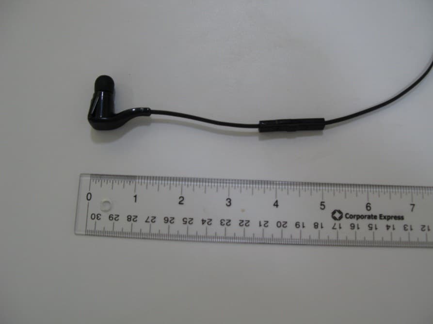
Click to zoom
Application Details
- Equipment Class
- DSS - Part 15 Spread Spectrum Transmitter
- Date of Grant
- Apr 25, 2013
- Application Purpose
- Original Equipment
- Date of Application
- Apr 25, 2013
- Equipment Note
- Bluetooth Headset
- Frequency Range
- 2402.00000000 - 2480.00000000
- Company
- HP Inc.
- Country
- United States
Documents & Files
Document Text
Text extracted from the exhibit documents filed with the FCC. Open a document above to read the original.
Users Manual
Project: Backbeat Go 2 Get Started Guide Date: 02.08.13 Component: folded, getting started guide File Name: 86993-31_BBGo2_GSG_en.ai Art Master Number: 86993-31 Part Number: 86992-31 Scale: 1:1 Resolution: 300dpi Placed Links: Fonts: Gesta (Light, Reg, Med, Bold), Arial Unicode, Bryant Reg Software: CS6 Printing Method: Offset lithography Inks and Finishes: (if applicable, include Cyan, Magenta, Yellow, Black) Black Pantone Cool Gray 8C Matte varnish Notes: Original Designer: Courtnay Perry E-mail: [email protected] Phone: 831-420-3024 Revisions: [DATE, designer’s name] E-mail: Phone: Changes to art after approval: Include date and give brief description Dieline Color Photography Text Other Authorized digital signatures on this document denote that all items have been verified. Marcom lead: Obtain all final approvals prior to release of file to the printer or Plamex. Designer: • Remove approval signatures if previously approved proof is going out with changes. • Post final files to Fuse Team Site and inform the team, including EMEA, that files are released. Please note: Final approval requires the examination of a printed proof or comp, in addition to quality control of the electronic file. Final Approval Checklist and Signatures BRAND AND ID [Art Director or Brand Manager; ID VP or Lead Designer] APPROVAL SIGNATURE: • Follows brand guidelines, approved design strategy, or creative brief MARCOM [Marcom lead] APPROVAL SIGNATURE: • Messaging • Grammar • Photography/illustrations (if any): Correct image(s) used, usage rights verified • Regulatory review (third-party logos, icons) • Legal review PLAMEX [Packaging Engineer] APPROVAL SIGNATURE: • Dieline • PN/AM • Non-template designs only: Received physical comp or match proof approval from SCZ Marcom, Brand, ID, and Production FINAL FILE PREP [Production Manager] APPROVAL SIGNATURE: • File reviewed by second designer • Pre-flight performed using Markzware or similar software • Final zipped archive contains: – .ai – .eps – from .eps: high res PDF (PDF/X-1a:2001) – from .eps: low res PDF, 1 page for each layer – from .ai: low res PDF with non-outlined fonts – fonts – links PRODUCTION QUALITY CONTROL [Production Manager] APPROVAL SIGNATURE: • Template (if any) • Text: – Spellcheck – No double spaces – Smart quotes used. No straight quotes or apostrophes – No improper soft or hard returns (Type > Show Hidden Characters) • Fonts: – Consistent style sheet application (if applicable) – Consistent spacing, font sizes and leading – No artificial bold or italic • Color: – .ai file is in CMYK color mode (File > Document Color Mode) – All colors in swatch palette not used in actual art have been deleted, including Black and White – Ink/finish names in art master slug match swatch names – Check ink overprinting (Attributes) – Inks/finishes specified and verified; PMS swatches pulled and confirmed – No RGB inks • Stray points and elements deleted • Measurements from original drawing deleted • 300 ppi photography, sized and/or rotated in Photoshop • .125” bleed • Non-bleeding elements maintain safe distance from dieline and folds (minimum .125”) • Separate layers for slug, die line, inks, foil, spot finishes NA Blanca Casteneda 02.08.13 Alberto Prudencio 02.08.13 Angela Kitchens 02.08.13 Designer Your new earbuds have enough power to pair and make a few calls. To access the charging port, insert your fingernail into the groove on top of the right earbud and pull down. It takes 2.5 hours to fully charge the earbuds. While charging, the indicator light is red and turns blue once charging is complete. CHARGE You can check the battery level by tapping either of the Volume buttons. Your earbuds announce battery status and the indicator light flashes to show the charge level. “Battery level high” = battery OK to fully charged “Battery level low” = less than 1 hour remaining “Recharge headset” = under 15 minutes remaini ng Blue flash = battery OK to fully charged Double red flash = battery low, less than 1 hour remaini ng Triple red flash = under 15 minutes remaini ng CHECK BATTERY LEVEL Bluetooth has a working “range” of up to 33 feet between the phone and earbuds before audio degrades and the connection is lost. Your earbuds try to reconnect after a lost Bluetooth connection. If they can’t, then tap the Audio/call button once or manually reconnect via the phone’s Bluetooth device menu. STAY CONNECTED You will hear an incoming call alert while listening to audio. When you take the call, your stored audio (downloaded tunes, video or podcasts) will pause. If you are listening to live streaming audio then it will mute, not pause, during your call. Once you end your call, your playback or streaming will resume. NEVER MISS A CALL Some smartphones allow you to use voice commands to activate features, such as voice- dialing or playing music. To activate your smartphone’s voice controls, press the Audio/call button until your phone prompts you for a command. USE VOICE COMMANDS GET STARTED BACKBEAT GO 2 ® Designed in Santa Cruz, California Find a local support number plantronics.com/support Read online user guide plantronics.com/documentation NEED MORE HELP? US Patents Pending pn86992-31 (02.13) am86993-31 1 For the best sound performance and fit, drape the earbuds around the back of your neck. 2 Choose between the different eartips to find the proper size for a good seal. FIT 3 Rotate the stabilizer to adjust the angle to achieve optimal fit and stability. The first time you power on your earbuds, it begins the pairing process. 1 Power on the earbuds. The indicator light, located on the right earbud, flashes red and blue to indicate pairing mode. 2 Activ ate Bluetooth ® on your phone and set it to search for new devices. •iPhone* Settings > General > Bluetooth > On GET PAIRED •Android ™ Smartphones* Settings > Wireless & Networks > Bluetooth: On > Scan for devices * Menus may vary by device. 3 Select “PLT_BBTGO2.” If necessary, enter four zeros (0000) for t…
Text truncated - open the document above for the full version.
Users Manual
en For Your Safety fr Pour Votre Sûreté es Para Su Seguridad pt Para Sua Segurança 2 en 3 Important Safety and Operational Information Please read the following safety and operational instructions before using your headset/headphones and accessories. Please keep these instructions for your reference. Additional warnings may be present on the product, packaging, or in the user instructions. This symbol identifies and alerts the user to the presence of important safety warnings. General Operating, storage and charging temperature is 0°C to 40°C (32°F to 104°F). Warnings • Exposure to high volume sound levels or excessive sound pressure may cause temporary or permanent damage to your hearing. Although there is no single volume setting that is appropriate for everyone, you should always use your headset/headphones with the volume set at moderate levels and avoid prolonged exposure to high volume sound levels. The louder the volume, the less time is required before your hearing could be affected. You may experience different sound levels when using your headset /headphones with different devices. The device you use and its settings affect the level of sound you hear. If you experience hearing discomfort, you should stop listening to the device through your headset/headphones and have your hearing checked by your doctor. To protect your hearing, some hearing experts suggest that you: 1. Set the volume control in a low position before putting your headset or headphones on your ears and use as low a volume as possible. 2. Avoid turning up the volume to block out noisy surroundings. Whenever possible, use your headset or headphones in a quiet environment with low background noise. 3. Limit the amount of time you use headsets or headphones at high volume levels. 4. Turn the volume down if the sound from the headset/ headphones prevent you from hearing people speaking near you. See www.plantronics.com/healthandsafety for more information on headsets/headphones and hearing. • Use of a headset/headphones that cover both ears will impair your ability to hear other sounds. Use of such headset/ headphones while operating a motor vehicle or riding a bicycle may create a serious hazard to you and/or others, and is illegal in most regions. • Check local laws regarding use of a mobile phone and headset/ headphones while driving. If you use the headset/headphones while driving ensure your attention and focus remain on driving safely. • Observe all signs and instructions that require an electrical device 4 en 5 or RF radio product to be switched off in designated areas, such as gas/refueling stations, hospitals, blasting areas, potentially explosive atmospheres, or aircraft. • This product is not a toy. Never allow children to play with the product — small parts may be a choking hazard. • Install and use eartips and earbuds in accordance with the instructions provided. Do not force eartips or earbuds down the ear canal. If either becomes lodged in the ear canal, seek medical attention immediately. • Ensure eartips and earbuds are kept clean and free of ear wax buildup to maintain the specified product performance. • If you experience a skin irritation after using this product, discontinue use and contact Plantronics. • Applying excessive pressure to the headset/headphones may injure the outer ear. Do not wear the headset /headphones while sleeping or in other situations where pressure may be exerted against the headset/headphones. • Do not disassemble or insert anything into the product or charger because this may cause damage to the internal components or cause injury to you. • If the product or charger: overheats; has a damaged cord or plug; has been dropped or damaged; has been dropped into water, disconnect any charger from its power supply, discontinue use of the product and contact Plantronics. • Prevent rain, moisture or other liquid from coming into contact with the product to protect against damage to your headset / headphone or injury to you. This warning is not applicable for ruggedized or sports products which are designed to withstand contact with moisture. To avoid the risk of electric shock, explosion, fire or leakage of corrosive or toxic chemicals, observe the following charging and battery warnings: Charging Warnings • Use only the charger supplied by Plantronics to charge the product. Do not use the chargers for any other purpose. Ensure that the voltage rating corresponds to the power supply you intend to use. • If your headset / headphone is designed to be charged with your mobile phone charger using a custom adapter, use only mobile phone chargers approved and provided by your mobile phone manufacturer. • Charge the headset / headphones according to the instructions supplied with the unit. • Plug the AC adapter or charger into an outlet that is near the equipment and will be easily accessible. • Never charge the battery where the temperature may fall below 0°C (32°F) or rise above 40°C (104°F) — for example, in an unattended motor vehicle. • Avoid charging the battery while it is unattended. 6 en 7 Battery Warnings To avoid the risk of explosion, fire or leakage of toxic chemicals, please observe the following warnings: • Do not dispose of the product or battery in a fire or heat above 100ºC. • Do not open, deform or mutilate the battery as there may be corrosive materials which can cause damage to eyes or skin and may be toxic if swallowed. • Do not attempt to open the headset/headphones or remove the battery. Recycling: Your product and batteries must be recycled or disposed of properly. Contact your local recycling center for information on proper disposal. Regulatory Notices FCC Requirements Part 15 Operation is subject to the following two conditions: 1. This device may not cause harmful interference. 2. This device must accept any interference received, including interference that may cause undesired operation. This equipment has been tested and found to comply with the limits for …
Text truncated - open the document above for the full version.
Cover Letter(s)
plantronics.com 345 Encinal St., Santa Cruz CA 95060 United States +1‐831‐426‐5858 April 10, 2013 UL VS Certification Division 47173 Benicia Street Fremont, CA 94538, USA To whom it may concern: I, the undersigned, hereby authorize UL VS, to act on our behalf in all manners relating to application for equipment authorization, including signing of all documents relating to these matters. Any and all acts carried out by UL VS on our behalf shall have the same effect as acts of our own. I, the undersigned, hereby certify that we are not subject to a denial of federal benefits, that includes FCC benefits, pursuant to Section 5301 of the Anti-Drug Abuse Act of 1988, 21 U.S.C. 853(a). In authorizing UL VS as our agent, we still recognize that we are responsible to: a) comply with the relevant provisions of the certification program; b) make all necessary arrangements for the conduct of the evaluation, including provision for examining documentation and access to all areas, records (including internal audit reports) and personnel for the purposes of evaluation (e.g. testing, inspection, assessment, surveillance, reassessment) and resolution of complaints; c) make claims regarding certification only in respect of the scope for which certification has been granted; d) do not use our product certification in such a manner as to bring the Certification Division into disrepute and not make any statement regarding our product certification which the Certification Division may consider misleading or unauthorized; e) upon suspension or cancellation of certification, discontinue use of all advertising matter that contains any reference thereto and return any certification documents as required by the Certification Division; f) use certification only to indicate the products are certified as being in conformity with specified standards; g) endeavor to ensure that no certificate or report nor any part thereof is used in a misleading manner; h) ensure that any reference to our product certification in communication media such as documents, brochures or advertising, complies with the requirements of the Certification Division; i) keep a record of all complaints made known to the us relating to the product’s compliance with requirements of the relevant standard and to make these records available to the Certification Division when requested; j) take appropriate action with respect to such complaints and any deficiencies found in products or services that affect compliance with the requirements for certification; k) document the actions taken. This authorization is valid until further written notice from the applicant. Sincerely, Peter Clark Compliance Engineering Manager
Cover Letter(s)
plantronics.com 345 Encinal St., Santa Cruz CA 95060 United States +1‐831‐426‐5858 April 10, 2013 Federal Communications Commission 7435 Oakland Mills Road Columbia MD 21046 Subject: Request for Long Term Confidentiality FCC ID: AL8-BBG2 To Whom It May Concern: Pursuant to the provisions of Sections 0.457 and 0.459 of the Commission’s rules (47 CFR §§ 0.457, 0.459), we are requesting the Commission to withhold the following attachments as confidential document from public disclosure indefinitely. Schematic Diagram Block Diagram Theory of Operation Above mentioned document contains detailed system and equipment description are considered as proprietary information in operation of the equipment. The public disclosure of above documents might be harmful to our company and would give competitor an unfair advantage in the market. Sincerely, Peter Clark Compliance Engineering Manager
Cover Letter(s)
plantronics.com 345 Encinal St., Santa Cruz CA 95060 United States +1‐831‐426‐5858 April 10, 2013 Federal Communications Commission 7435 Oakland Mills Road Columbia MD 21046 Subject: Request for Short Term Confidentiality FCC ID: AL8-BBG2 To Whom It May Concern: Pursuant to Public Notice DA 04-1705 of the Commission’s policy, in order to comply with the marketing regulations in 47 CFR §2.803 and the importation rules in 47 CFR §2.1204, while ensuring that business sensitive information remains confidential until the actual marketing of newly authorized devices. We are requesting the commission to grant short-term confidentiality request on the following attachments until August 1, 2013. External Photos Internal Photos Test Setup Photos User Manual It is our understanding that all measurement test reports, FCC ID label format and correspondent during certification review process cannot be granted as confidential documents and those information will be available for public review once the grant of equipment authorization is issued. Sincerely, Peter Clark Compliance Engineering Manager
Cover Letter(s)
plantronics.com 345 Encinal St., Santa Cruz CA 95060 United States +1‐831‐426‐5858 April 10, 2013 Compliance Certification Services Certification Division 47173 Benicia Street Fremont, CA 94538, USA To whom it may concern: Regarding FCC ID: AL8-BBG2, we, the undersigned, declare that the equipment complies with the Bluetooth CORE Specification 2.1 which includes: 1) a pseudorandom hopping sequence 2) equal on average channel use 3) a receiver with a compliant input bandwidth, based on the measured 20 dB emission bandwidth 4) a receiver with the ability to hop in synchronization with the transmitter 5) a frequency hopping system compliant with all pertinent requirements when presented with a lengthy data stream 6) a frequency hopping system compliant with the non-coordination requirement Sincerely, Peter Clark Compliance Engineering Manager
External Photos
External Photos AL8‐BBG2 For Scale Front Back Top Bottom Left Right
ID Label/Location Info
Label and Location for AL8‐BBG2 Label: Location:
Internal Photos
Internal Photos AL8‐BBG2 For Scale Right PCBA Installed Right PCBA Top Right PCBA Bottom Right PCBA Connector Top Right PCBA Connector Bottom Control PCBA Top Control PCBA Bottom Left Battery
RF Exposure Info
REPORT NO: 13U14904-2A DATE: APRIL 25, 2013 FCC ID: AL8-BBG2 IC: 457A-BBG2 Page 153 of 157 COMPLIANCE CERTIFICATION SERVICES (UL CCS) FORM NO: CCSUP4701D 47173 BENICIA STREET, FREMONT, CA 94538, USA TEL: (510) 771-1000 FAX: (510) 661-0888 This report shall not be reproduced except in full, without the written approval of UL CCS. 10. MAXIMUM PERMISSIBLE EXPOSURE As the DUT is a portable device it was assessed in accordance using the standalone test exclusion guidelines of FCC KDB 447498 D01 General RF Exposure Guidance v05. RF exposure evaluation was not required as determined in the following The 1-g and 10-g SAR test exclusion thresholds for 100 MHz to 6 GHz at test separation distances ≤ 50 mm are determined by: [(max. power of channel, including tune-up tolerance, mW)/(min. test separation distance, mm)] · [√f(GHz)] ≤ 3.0 for 1-g SAR and ≤ 7.5 for 10-g extremity SAR, where f(GHz) is the RF channel transmit frequency in GHz Power and distance are rounded to the nearest mW and mm before calculation17 The result is rounded to one decimal place for comparison The test exclusions are applicable only when the minimum test separation distance is ≤ 50 mm and for transmission frequencies between 100 MHz and 6 GHz. When the minimum test separation distance is < 5 mm, a distance of 5 mm is applied to determine SAR test exclusion. dBmmW BluetoothBluetooth2400-0.65100.310<3 SAR exclusion Threshold Limit (1g SAR) AntennaTx Frequency (MHz) Output power Separation distance (mm) SAR exclusion Threshold value
Test Report
FCC CFR47 PART 15 SUBPART C INDUSTRY CANADA RSS-210 ISSUE 8 CERTIFICATION TEST REPORT FOR BLUETOOTH HEADSET MODEL NUMBER: BackBeat GO 2 FCC ID:AL8-BBG2 IC:457A-BBG2 REPORT NUMBER: 13U14904-2, REVISION A ISSUE DATE: APRIL 25, 2013 Prepared for PLANTRONICS, INC. 345 ENCINAL STREET SANTA CRUZ, CA 95060, U.S.A. Prepared by UL CCS 47173 BENICIA STREET FREMONT, CA 94538, U.S.A. TEL: (510) 771-1000 FAX: (510) 661-0888 REPORT NO: 13U14904-2A DATE: APRIL 25, 2013 FCC ID: AL8-BBG2 IC: 457A-BBG2 Page 2 of 157 COMPLIANCE CERTIFICATION SERVICES (UL CCS) FORM NO: CCSUP4701D 47173 BENICIA STREET, FREMONT, CA 94538, USA TEL: (510) 771-1000 FAX: (510) 661-0888 This report shall not be reproduced except in full, without the written approval of UL CCS. Revision History Rev. Issue Date Revisions Revised By -- 04/15/2013 Initial Issue F. de Anda A 4/25/2013 Added MPE T. LEE REPORT NO: 13U14904-2A DATE: APRIL 25, 2013 FCC ID: AL8-BBG2 IC: 457A-BBG2 Page 3 of 157 COMPLIANCE CERTIFICATION SERVICES (UL CCS) FORM NO: CCSUP4701D 47173 BENICIA STREET, FREMONT, CA 94538, USA TEL: (510) 771-1000 FAX: (510) 661-0888 This report shall not be reproduced except in full, without the written approval of UL CCS. TABLE OF CONTENTS 1. ATTESTATION OF TEST RESULTS ................................................................................. 5 2. TEST METHODOLOGY ..................................................................................................... 6 3. FACILITIES AND ACCREDITATION ................................................................................. 6 4. CALIBRATION AND UNCERTAINTY ................................................................................ 6 4.1. MEASURING INSTRUMENT CALIBRATION .............................................................. 6 4.2. SAMPLE CALCULATION ............................................................................................ 6 4.3. MEASUREMENT UNCERTAINTY ............................................................................... 6 5. EQUIPMENT UNDER TEST ............................................................................................... 7 5.1. DESCRIPTION OF EUT .............................................................................................. 7 5.2. MAXIMUM OUTPUT POWER...................................................................................... 7 5.3. DESCRIPTION OF AVAILABLE ANTENNAS .............................................................. 7 5.4. SOFTWARE AND FIRMWARE .................................................................................... 7 5.5. WORST-CASE CONFIGURATION AND MODE .......................................................... 7 5.6. DESCRIPTION OF TEST SETUP ................................................................................ 8 6. TEST AND MEASUREMENT EQUIPMENT ......................................................................11 7. ANTENNA PORT TEST RESULTS ...................................................................................12 7.1. BASIC DATA RATE GFSK MODULATION .................................................................12 7.1.1. 20 dB AND 99% BANDWIDTH ............................................................................12 7.1.2. HOPPING FREQUENCY SEPARATION .............................................................16 7.1.3. NUMBER OF HOPPING CHANNELS ..................................................................18 7.1.4. AVERAGE TIME OF OCCUPANCY ....................................................................23 7.1.5. OUTPUT POWER ...............................................................................................30 7.1.6. CONDUCTED SPURIOUS EMISSIONS ..............................................................34 7.2. ENHANCED DATA RATE 8PSK MODULATION ........................................................43 7.2.1. 20 dB AND 99% BANDWIDTH ............................................................................43 7.2.2. HOPPING FREQUENCY SEPARATION .............................................................47 7.2.3. NUMBER OF HOPPING CHANNELS ..................................................................49 7.2.4. AVERAGE TIME OF OCCUPANCY ....................................................................52 7.2.5. OUTPUT POWER ...............................................................................................59 7.2.6. AVERAGE POWER .............................................................................................63 7.2.7. CONDUCTED SPURIOUS EMISSIONS ..............................................................64 7.3. ENHANCED DATA RATE DQPSK MODULATION .....................................................69 7.3.1. 20 dB AND 99% BANDWIDTH ............................................................................69 7.3.2. HOPPING FREQUENCY SEPARATION .............................................................73 7.3.3. NUMBER OF HOPPING CHANNELS ..................................................................75 7.3.4. AVERAGE TIME OF OCCUPANCY ....................................................................80 7.3.5. OUTPUT POWER ...............................................................................................87 7.3.6. CONDUCTED SPURIOUS EMISSIONS ..............................................................91 REPORT NO: 13U14904-2A DATE: APRIL 25, 2013 FCC ID: AL8-BBG2 IC: 457A-BBG2 Page 4 of 157 COMPLIANCE CERTIFICATION SERVICES (UL CCS) FORM NO: CCSUP4701D 47173 BENICIA STREET, FREMONT, CA 94538, USA TEL: (510) 771-1000 FAX: (510) 661-0888 This report shall not be reproduced except in full, without the written approval of UL CCS. 8. RADIATED TEST RESULTS ........................................................................................... 100 8.1. LIMITS AND PROCEDURE ...................................................................................... 100 8.2. TRANSMITTER ABOVE 1 GHz ....................................................…
Text truncated - open the document above for the full version.
Test Setup Photos
REPORT NO: 13U14904-2A DATE: APRIL 25, 2013 FCC ID: AL8-BBG2 IC: 457A-BBG2 Page 154 of 157 COMPLIANCE CERTIFICATION SERVICES (UL CCS) FORM NO: CCSUP4701D 47173 BENICIA STREET, FREMONT, CA 94538, USA TEL: (510) 771-1000 FAX: (510) 661-0888 This report shall not be reproduced except in full, without the written approval of UL CCS. 11. SETUP PHOTOS ANTENNA PORT CONDUCTED RF MEASUREMENT SETUP RADIATED RF MEASUREMENT SETUP ANTENNA PORT CONDUCTED PHOTO RADIATED FRONT PHOTO REPORT NO: 13U14904-2A DATE: APRIL 25, 2013 FCC ID: AL8-BBG2 IC: 457A-BBG2 Page 155 of 157 COMPLIANCE CERTIFICATION SERVICES (UL CCS) FORM NO: CCSUP4701D 47173 BENICIA STREET, FREMONT, CA 94538, USA TEL: (510) 771-1000 FAX: (510) 661-0888 This report shall not be reproduced except in full, without the written approval of UL CCS. RADIATED RF MEASUREMENT SETUP FOR PORTABLE CONFIGURATION X-AXIS FRONT PHOTO Y-AXIS FRONT PHOTO REPORT NO: 13U14904-2A DATE: APRIL 25, 2013 FCC ID: AL8-BBG2 IC: 457A-BBG2 Page 156 of 157 COMPLIANCE CERTIFICATION SERVICES (UL CCS) FORM NO: CCSUP4701D 47173 BENICIA STREET, FREMONT, CA 94538, USA TEL: (510) 771-1000 FAX: (510) 661-0888 This report shall not be reproduced except in full, without the written approval of UL CCS. POWERLINE CONDUCTED EMISSIONS MEASUREMENT SETUP Z-AXIS FRONT PHOTO LINE CONDUCTED FRONT PHOTO REPORT NO: 13U14904-2A DATE: APRIL 25, 2013 FCC ID: AL8-BBG2 IC: 457A-BBG2 Page 157 of 157 COMPLIANCE CERTIFICATION SERVICES (UL CCS) FORM NO: CCSUP4701D 47173 BENICIA STREET, FREMONT, CA 94538, USA TEL: (510) 771-1000 FAX: (510) 661-0888 This report shall not be reproduced except in full, without the written approval of UL CCS. END OF REPORT LINE CONDUCTED BACK PHOTO
Contact Information
Applicant
Richard Tarsio(US/CAN TRSE Worldwide Technical Regulations)
Technical Contact
Test Firm
Compliance Certification ServicesThu Chan
Technical Specifications
| # | Rule Parts | Frequency Range | Power Output |
|---|---|---|---|
| 1 | 15C | 2.40 GHz - 2.48 GHz | 5.64 mW |
Other Applications from HP Inc.
AL8-PWPTF620P
Feb 03, 2026Wireless Charge Stand
Equipment Class
DCD - Part 15 Low Power Transmitter Below 1705 kHzAL8-PBF620F
Jan 23, 2026Bluetooth Headset
Equipment Class
DTS - Digital Transmission SystemAL8-PBVOYX2
Jun 20, 2024Bluetooth Base
Equipment Class
DTS - Digital Transmission System
AL8-VF2R
Mar 07, 2024Wireless Bluetooth Earphones
Equipment Class
DTS - Digital Transmission System
AL8-CBVS1
Oct 16, 2023Wireless Charge Stand
Equipment Class
DXX - Part 15 Low Power Communication Device Transmitter