AL8-D100XDECT USB Audio Transmitter
HP Inc.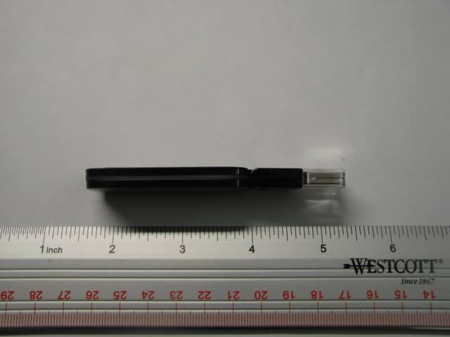
Click to zoom
Application Details
- Equipment Class
- PUB - Part 15 Unlicensed PCS Base Station
- Date of Grant
- Mar 24, 2010
- Application Purpose
- Original Equipment
- Date of Application
- Mar 24, 2010
- Equipment Note
- DECT USB Audio Transmitter
- Frequency Range
- 1921.53000000 - 1928.45000000
- Company
- HP Inc.
- Country
- United States
Documents & Files
Document Text
Text extracted from the exhibit documents filed with the FCC. Open a document above to read the original.
Users Manual
Savi ™ W430 ™ Wireless Headset System Quick Start Guide Guide de démarrage rapide Guia de Início Rápido 3 en 1 4.4 4.5 1.1 1.2 2 3 4 Welcome Congratulations on purchasing your new Plantronics product. This Quick Start Guide contains instructions for setting up and using your Savi W430 (D100 + WH210 Headset) Wireless Headset System. Please refer to the separate safety instructions for important product safety information prior to installation or use of the product. System Requirements The minimum system requirements for Savi W430 are as follows: • Supported Operating Systems: Windows XP ® , Windows Vista ® , Windows ® 7 • Processor: 400 MHz Pentium ® processor or equivalent (Minimum); 1 GHz Pentium processor or equivalent (Recommended) • RAM: 96 MB (Minimum); 256 MB (Recommended) • Hard Disk: 280 MB (Minimum); 500 MB (Recommended) • Display: 800 x 600, 256 colors (Minimum); 1024 x 768 high color, 32-bit (Recommended) • Internet Explorer ® V6 or better must be on the user’s system (Required) Complete User Guide and Plantronics Software We highly recommend that you refer to the complete user guide located on the CD. The user guide provides full details on how to use your system. We also recommend that you install the Plantronics Unified Runtime Engine and Control Panel located on the CD. With Plantronics software installed you can: • Remotely answer incoming softphone calls • Customize your headset and USB adapter settings to your personal preferences • Automatically manage your PC multimedia so you never miss a call • Quickly access links to product support and software/firmware upgrade information Registering Your Product Visit plantronics.com/productregistration to register your product online so we can provide you with the best service and technical support. Getting Assistance The Plantronics Technical Assistance Center is ready to assist you. You can find answers to frequently asked questions, ask a question using e-mail, receive service over the internet, or speak directly with a representative. Visit plantronics.com/support. 45 en en Base Power Supply USB Charging Cable Indicator Light Microphone Call Control Button Volume Down Button (also controls mute) Volume Up Button Headset with Pre-Installed Eartip USB Adapter Indicator Light Subscription Button Extra Eartips CD includes: • Plantronics Software • Complete User Guide Charger Base Charging Indicator Light 1 Connecting USB Adapter to PC 1-1. Insert the USB adapter into USB Port on PC. The indicator light on the USB adapter will be solid red to indicate the USB adapter is powered on and will turn solid green when it finds the headset. 1-2. The USB adapter can be folded as shown. NOTE The headset may need to be charged before the USB adapter can find it. ImPORTANT NOTE It is recommended that Windows be updated with Service Pack levels listed below: Microsoft Windows XP Service Pack 3 (SP3) or later Microsoft Windows Vista Service Pack 1 (SP1) or later 2 Connecting Power Supply to Charger Base 2-1. Connect the base power supply into the power jack on the charger base. 2-2. Connect the power supply to the outlet. The charging indicator light will be solid green. 3 Docking and Charging Headset 3-1. Gently push the headset into the charge cradle. The charging indicator light on the charger base will flash green to indicate that the headset battery is charging. 3-2. Charge for at least 20 minutes prior to the first use. A full charge takes 3 hours. NOTE The USB charging cable can also be used to charge the headset. To successfully charge your headset with the USB cable the PC must be on and in an active state (not standby). The charging time will vary according to the number of other devices drawing power from the PC’s USB port(s). Charging time 20 min ..................... minimum charge before first use 3 hours ................... Full charge 67 fr en Bienvenue Félicitations pour votre nouveau produit Plantronics. Ce guide de démarrage rapide contient les directives d’installation et d’utilisation de votre nouveau système de micro-casque sans fil Savi W430 (D100 et micro-casque WH210). Veuillez lire les consignes de sécurité fournies séparément avant d’installer ou d’utiliser le produit. Configuration système requise La configuration système requise pour le Savi W430 est la suivante : • Systèmes d’exploitation compatibles : Windows XP®, Windows Vista®, Windows® 7 • Processeur : processeur Pentium® à 400 MHz ou équivalent (minimum); processeur Pentium à 1 GHz ou équivalent (recommandé) • Mémoire : 96 Mo (minimum); 256 Mo (recommandé) • Disque dur : 280 Mo (minimum); 500 Mo (recommandé) • Affichage : 800 x 600, 256 couleurs (minimum); 1 024 x 768, couleurs 32 bits (recommandé) • Internet Explorer® version 6 ou ultérieure installé sur le système de l’utilisateur (obligatoire) Guide de l’utilisateur complet et logiciel Plantronics Nous vous recommandons fortement de consulter le guide de l’utilisateur qui se trouve sur le CD. Ce guide de l’utilisateur explique de façon détaillée comment utiliser votre système. Nous vous recommandons également d’installer Plantronics Unified Runtime Engine et Plantronics Control Panel disponibles sur le CD. Une fois le logiciel de Plantronics installé, vous pouvez : • Répondre à distance aux appels entrants effectués à l’aide d’une application de téléphonie • Personnaliser les réglages du micro-casque et de la base selon vos préférences • Gérer automatiquement le lecteur multimédia de l’ordinateur afin de ne jamais rater un appel • Accéder rapidement à des liens vers du soutien aux produits ou vers des renseignements sur la mise à jour du logiciel ou du micrologiciel Enregistrement de votre produit Visitez le site plantronics.com/productregistration pour enregistrer votre produit en ligne. Nous pourrons ainsi vous proposer le meilleur service et le meilleur soutien technique possible. Aide Le centre d’assistance technique de Plantronics est là pour vous aider. Vous pouvez y trouver les réponses aux questio…
Text truncated - open the document above for the full version.
Cover Letter(s)
Worldwide Headquarters 345 Encinal Street Santa Cruz, CA 95060 March 10, 2010 Federal Communications Commission 7435 Oakland Mills Road Columbia MD 21046 Subject: Request for Long Term Confidentiality FCC ID: AL8-D100X To Whom It May Concern: Pursuant to the provisions of Sections 0.457 and 0.459 of the Commission’s rules (47 CFR §§ 0.457, 0.459), we are requesting the Commission to withhold the following attachments as confidential document from public disclosure indefinitely. Schematic Diagram Block Diagram Theory of Operation Above mentioned document contains detailed system and equipment description are considered as proprietary information in operation of the equipment. The public disclosure of above documents might be harmful to our company and would give competitor an unfair advantage in the market. Sincerely, Peter Clark Compliance Manager
Cover Letter(s)
Worldwide Headquarters 345 Encinal Street Santa Cruz, CA 95060 March 10, 2010 Federal Communications Commission 7435 Oakland Mills Road Columbia MD 21046 Subject: Request for Short Term Confidentiality FCC ID: AL8-D100X To Whom It May Concern: Pursuant to Public Notice DA 04-1705 of the Commission’s policy, in order to comply with the marketing regulations in 47 CFR §2.803 and the importation rules in 47 CFR §2.1204, while ensuring that business sensitive information remains confidential until the actual marketing of newly authorized devices. We are requesting the commission to grant short- term confidentiality request on the following attachments until July 1, 2010. External Photos Internal Photos Test Setup Photos User Manual It is our understanding that all measurement test reports, FCC ID label format and correspondent during certification review process cannot be granted as confidential documents and those information will be available for public review once the grant of equipment authorization is issued. Sincerely, Peter Clark Compliance Manager
Cover Letter(s)
From: Ilarina, Alvin Sent: Wednesday, March 24, 2010 5:53 PM To: PCTEST TCB/CB Cc: PCTEST - Gregory Czumak; PCTEST - Courtenay Geraghty Subject: RE: Questions Regarding FCC ID: AL8-D100X Greetings, Please find the responses to the questions below. Thanks! A lvin Ilarina Compliance Engineer PLANTRONICS From: PCTEST TCB/CB Sent: Thursday, March 18, 2010 2:04 PM To: Ilarina, Alvin Subject: Questions Regarding FCC ID: AL8-D100X T o: Mr. Alvin Ilarina/ Plantronics From: Mr. Gregory Czumak / PCTEST TCB RE: FCC ID: AL8-D100X Applicant: Plantronics Co rrespondence Reference Number: AL8Y0286 Confirmation Number: Y1003120286 Date of Original Email: March 18, 2010 Subject: Request for additional information In regards to your recent TCB application referenced a bove, we kindly request that you provide the following additional information. 1 . The FCC ID label shows an FCC DoC logo. Is the pc peripheral (JBP) portion of the EUT authorized under DoC? If so, then there is no need to submit the 15B test report. If the JBP portion is not authorized under DoC, but rather, certification is sought for it, then the DoC logo must be removed from the FCC ID label- please do so and resubmit it. Please disregard the submitted Part 15B test report. We would like to continue with DoC for the pc peripheral portion of the EUT. 2. In the 15D test report, p. 15/101 lists the maximum measured output power as 18.83 dBm, but the test data (pp. 25-27) shows that the highest measured output level is 18.62 dBm. Please revise the table on p.15 accordingly. Please find attached the corrected report “11_Base D100 Certif Testing Record Final_March23_2010.pdf”. T he item indicated above must be submitted before pro cessing can continue on the above referenced application. Sincerely, Gregory Czumak Senior Certification Engineer Quality Manager PCTEST Engineering Laboratory, Inc. 6660-B Dobbin Road Columbia, MD 21045 410-290-6652 410-290-6654 (Fax) [email protected] This communication and its attachments contain information from PCTEST Engineering Laboratory, Inc., and is intended for the exclusive use of the recipient (s) named above. It may contain information that is confidential and/or legally privileged. Any unauthorized use that may compromise that confidentiality via distribution or disclosure is prohibited. Please notify the sender immediately if you receive this communication in error, and delete it from your computer system. Usage of PCTEST email addresses for non-business related activities is strictly prohibited. No warranty is made that the e-mail or attachment(s) are free from computer virus or other defect. Thank you. CONFIDENTIALITY NOTICE: This e-mail transmission, and any documents, files or previous e-mail messages a ttached to it, may contain information that is confidential and/or legally privileged. If you are not the intended recipient, or a person responsible for delivering it to the intended recipient, please DO NOT disclose the contents to another person, store or copy the information in any medium, or use any of the information contained in or attached to this transmission for any purpose. If you have received this transmission in error, please immediately notify the sender by reply email or at [email protected], and destroy the original transmission and its attachments without reading or saving in any manner. For further information about Plantronics - the Company, its products, brands, partners, please visit our website www.plantronics.com.
External Photos
External Photos for AL8-D100X Top Bottom Left Right
ID Label/Location Info
FCC ID Label and Location Label Location
Internal Photos
Internal Photos AL8-D100X Top PCB Top PCB Shield cap removed Top PCB Shield removed Bottom PCB
RF Exposure Info
Applicant: Plantronics Inc. Model: D100/-M FCC ID: AL8-D100X IC: 457A-D100X DUT Type: Portable UPCS/LE-PCS DECT USB Audio Adapter Freq. Range: 1921.536 - 1928.448 MHz 2010 Celltech Labs Inc. This document is not to be reproduced in whole or in part without the prior written permission of Celltech Labs Inc. Page 1 of 1 RFx Exhibit Serial No. 020810AL8-T1004-S15D RFx Exhibit Issue Date March 08, 2010 RFx Exhibit Revision No. Rev. 1.1 (2nd Release) Test Lab Certificate No. 2470.01 RF EXPOSURE SUMMARY PER FCC KDB INQUIRY TRACKING NUMBER 517129 Plantronics Model: D100/D100-M DECT UPCS Wireless USB Audio Adapter FCC ID: AL8-D100X FCC Response to KDB Inquiry Tracking Number 517129 This device has been excluded from SAR testing requirements based on the source-based time-averaged conducted output power is less than 60/f. This document serves as the RF exposure exhibit in the FCC Form 731 application in lieu of a SAR report and has been reviewed and accepted by the FCC prior to submittal to the TCB. RF Exposure Environment The D100 and D100-M (MOC version) wireless USB audio adapter is intended for operation in the General Population / Uncontrolled RF exposure environment. Operational Description The D100/D100-M is a wireless USB audio system. The D100/D100-M adapter plugs into a standard PC USB jack and subscribes to a provided WH210 headset. A WH210 headset (FCC ID: AL8-WH210) is provided for device pairing. The EUT system is a UPCS TDMA system which “further divides access in time” in the context of clause 6.2.2 of C63.17-2006. Frame period is 10mS. There are 24 timeslots per frame, with one of the first 12 timeslots used for the headset transmissions and one of the last 12 timeslots used for the base (D100/D100-M) transmissions. Transmit and receive timeslots are 5mS apart in time. Duty Cycle Standard UPCS single slot duty cycle is 390us transmit per 10ms frame for a duty cycle of 3.9% (1 slot out of 24). The worst- case (maximum) transmission duration is CAT-iq longslot wideband mode which is equivalent to 1.5 standard DECT/UPCS slots (approximately 590us duration) for a duty cycle of 5.9% (1.5 slots out of 24). Note: The D100/D100-M does not support the proprietary 780us dual-slot wideband mode (2 slots out of 24) used on other Plantronics DECT headset systems. RF Output Power Manufacturer’s Rated Maximum Peak Conducted Power = 18.4 dBm (69.2 mW) (1/24 slots - 390us transmit per 10ms frame) Manufacturer’s Specified Source-Based Time-Averaged Duty Cycle = 3.9% Source-Based Time-Averaged Conducted Output Power = 4.3 dBm (2.7 mW) 60/f (GHz) mW = 31.1 mW Source-based time-averaged conducted output power = < 60/f (1.5/24 slots - 590us transmit per 10ms frame) Manufacturer’s Specified Source-Based Time-Averaged Duty Cycle = 5.9% Source-Based Time-Averaged Conducted Output Power = 6.1 dBm (4.1 mW) 60/f (GHz) mW = 31.1 mW Source-based time-averaged conducted output power = < 60/f RF Exposure Exhibit Revision No.s Revision 1.1 - March 08, 2010 List 2 Models & Add Manufacturer Statement Revision 1.0 - Initial Release - March 08, 2010 Manufacturer Statement re Model Difference The D100 and D100-M are electrically and mechanically identical. The only difference is that the D100-M is optimized (contains firmware) for compatibility with Microsoft Office Communicator.
Test Report
1/101 Exhibit #11 Conducted RF and Spectral Etiquette Measurements to Support the Certification of the Wireless Office Base D100, FCC ID AL8-D100X. Plantronics, John Mihelic, March 24, 2010. I. Background 2 A. EUT description 2 B. Manufacturer’s attestations, mandatory declarations and descriptions 2 C. Standard test configurations 4 D. Calibration 7 II. Test Results Summary Base EUT 12 III. Tests of clause 6, Base EUT 23 A. Clause 6.1 Emissions tests for the Base EUT 23 B. Clause 6.2 Tests of frequency and time stability for the Base EUT 58 IV. Tests of clause 7, Base EUT 64 A. Clause 7.3.2 Upper threshold for EUTs which implement the LIC procedure, Base EUT 64 B. Clause 7.3.3 Least interfered channel (LIC) procedure test, Base EUT 66 C. Clause 7.3.4 Selected channel confirmation, Base EUT 70 D. Clause 7.4 Threshold monitoring bandwidth Base EUT 70 E. Clause 7.5 Reaction time and monitoring interval, Base EUT 71 V. Tests of clause 8, Base EUT 80 A. Clause 8.1.1 Access Criteria Test Interval, Base EUT 80 B. Clause 8.2.1 Acknowledgement, Base EUT 88 C. Clause 8.2.2 Transmission duration, Base EUT 92 VI. Appendix A WBM (Wide Band Mode), Base EUT 93 A. Clause 6.1.2 Peak transmit power, Base EUT in WBM 94 B. Clause 6.1.3 Emission bandwidth B, Base EUT in WBM 95 C. Clause 6.1.6 Emissions, Base EUT in WBM maximum power 95 VII. Appendix B Power Control-minimum output power, Base EUT 96 A. Clause 6.1.3 Emission bandwidth, Base EUT, in minimum power mode and WBM 97 B. Clause 6.1.6 Emissions, Base EUT 100 2/101 I. Background A. EUT description The Wireless Office Base, D100, is a base station unit which can receive and transmit audio to/from its companion headset assembly. The base unit is a USB audio device that interfaces to a standard PC USB port. The base unit is an intentional radiator, designed in accordance with the requirements of 47CFR15 subpart D. This document reports compliance of the Base to the test parameters of C63.17-2006. The Base EUT is capable of RF power control. The power control modes are fixed, or adaptive. Adaptive power control will allow the RF transmitter to adjust the output power from a maximum of 19dBm to a minimum of 2dBm in four 5-7dB steps. Fixed power mode does not allow power control. The user can select between adaptive or fixed but can not set the power range, this is done during EUT factory set up. Compliance to C63.17-2006 is documented in Appendix A which repeats any testing that may operate differently from maximum power mode or affect the access threshold. The Base companion device can initiate a link in a wideband mode using the P00J Longslot configuration for transmission and receive, but the Base does not perform the access threshold check or initiate the WBM communications traffic link; the companion headset performs the proper access checks per ANSI C63.17-2006 clause 8.3.1 or 2. The specific unit tested is Base #1 for emissions bandwidth, spectral etiquette, and access criteria. The RF output power and emissions testing was performed on the SAR test sample VB2 01CFE21F8. B. Manufacturer’s attestations, mandatory declarations and descriptions The Wireless Office D100 Base uses digital modulation. Clause 4.11 in C63.17-2006 requires the following declarations to be made by the manufacturer. These declarations are used in demonstrating compliance with certain sections of 47CFR15 subpart D, and in support of test parameters within C63.17-2006. The channel plan. Five RF carriers are used, as follows: 1928.448 MHz. 1926.720 MHz. 1924.992 MHz. 1923.264 MHz. 1921.536 MHz. Maximum EUT antenna gain GA (dBi), and orientation and polarization for maximum gain. The maximum Base EUT antenna gain is 3dBi. Maximum peak power level Maximum specified peak conducted power level for the Base EUTs is +19.5dBm. Minimum peak power level The maximum power level at the minimum RF power setting is specified peak conducted power level for the headset EUTs is +2dBm. Emission bandwidth Emission bandwidth measured according to the procedures of C63.17-2006 clause 6.1.3 for the Base EUT is 1.45MHz. Nominal receive bandwidth 3/101 Nominal receive bandwidth is +/-500kHz. Frame period and time slot plan, if TDMA techniques are used The EUT system is a TDMA system which “further divides access in time” in the context of clause 6.2.2 of C63.17- 2006. Frame period is 10mS. There are 24 timeslots per frame, with one of the first 12 timeslots used for the headset transmissions and one of the last 12 timeslots used for the base transmissions. Transmit and receive timeslots are 5mS apart in time. Transient events occur during which two non-adjacent timeslots may be in use by the base during the setup of the communications channel, or by both the base and the headset EUT as the system does a soft handoff in response to interference. Minimum and maximum burst length, if TDMA techniques are used Minimum burst length is 90uS, the beacon transmissions from the base when a communications channel is not open. Maximum burst length is 780uS, transmissions from the Base when a communications channel is open in wideband mode. Minimum and maximum operating temperature range declared to the end-user The minimum operating temperature is +4C. The maximum operating temperature is +44C. Whether a system built with the EUT does or does not operate under the provisions of 47CFR15.323(c)(10) to test for deferral only in conjunction with a companion device The EUT system does not use the provisions of 47CFR15.323(c)(10) to enable testing for access criteria only in one element of the system. The headset EUTs implement the access criteria tests. Whether a system built with the EUT does or does not implement the provisions of 47CFR15.323(c)(5) enabling the use of the upper threshold for deferral The EUT system does implement the provisions of 47CFR15.323(c)(5), and uses the upper threshold for deferral. The nominal value of the deferral threshold The nominal value of the deferral threshold implemented in the Bas…
Text truncated - open the document above for the full version.
Test Setup Photos
23/101 III. Tests of clause 6, Base EUT A. Clause 6.1 Emissions tests for the Base EUT For the tests of clause 6.1 of C63.17-2006, the test platform and Base EUT are configured according to test configuration #1, Conducted emissions tests, Base EUT, of section (I) of this document. The Base EUT is established in a communications channel with the headset companion device by means of a radiative-coupled connection, though the Base EUT is in conducted connection to the spectrum analyzer, per figure 3 of C63.17-2006 in clause 6.1.1. Administrative commands are used to set the base to the desired carrier for the test. Fig. 6 - Base EUT in direct connection with spectrum analyzer and radiated connection with base companion device, for the tests of clause 6.1. 24/101 Fig. 7 – Detail of the attachment of the RF connection for conducted measurements.
Contact Information
Applicant
Richard Tarsio(US/CAN TRSE Worldwide Technical Regulations)
Technical Contact
PCTEST Engineering Laboratory, Inc.Randy Ortanez
[email protected]410-290-6652
6660-B Dobbin Road · Columbia, Maryland · United States
Test Firm
Elliott Laboratories LLCDavid Bare
Technical Specifications
| # | Rule Parts | Frequency Range | Power Output |
|---|---|---|---|
| 1 | 15D | 1.92 GHz - 1.93 GHz | 73.00 mW |
Other Applications from HP Inc.
AL8-PWPTF620P
Feb 03, 2026Wireless Charge Stand
Equipment Class
DCD - Part 15 Low Power Transmitter Below 1705 kHzAL8-PBF620F
Jan 23, 2026Bluetooth Headset
Equipment Class
DTS - Digital Transmission SystemAL8-PBVOYX2
Jun 20, 2024Bluetooth Base
Equipment Class
DTS - Digital Transmission System
AL8-VF2R
Mar 07, 2024Wireless Bluetooth Earphones
Equipment Class
DTS - Digital Transmission System
AL8-CBVS1
Oct 16, 2023Wireless Charge Stand
Equipment Class
DXX - Part 15 Low Power Communication Device Transmitter