AL8-D645Bluetooth Headset
HP Inc.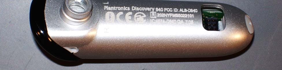
Click to zoom
Application Details
- Equipment Class
- DSS - Part 15 Spread Spectrum Transmitter
- Date of Grant
- Nov 13, 2005
- Application Purpose
- Original Equipment
- Date of Application
- Nov 13, 2005
- Equipment Note
- Bluetooth Headset
- Frequency Range
- 2402.00000000 - 2480.00000000
- Company
- HP Inc.
- Country
- United States
Documents & Files
Document Text
Text extracted from the exhibit documents filed with the FCC. Open a document above to read the original.
Users Manual
DISCOVERY ™ 645 BLUETOOTH ® HEADSET WITH DSP V2.0 USER GUIDE_ GUÍA DEL USARIO_ Register Your Product Online Visit www.plantronics.com/productregistrationto register your product online so we can provide you with the best possible service and technical support. TABLE OF CONTENTS Package Contents and Features/[Spanish]1 Connecting the Components/2 Charging/3 Powering/4 Pairing/5 Adjusting Fit/6 Using Your Headset/7 Indicator Lights/9 Accessories/10 Troubleshooting/11 Technical Assistance/12 Warranty/12 Regulatory Notices/13 1 PACKAGE CONTENTS & FEATURES 1.Headset 2.Indicator Light 3.Call Control Button (On/Off) 4.Volume/Mute Button 5.Headset Carrying Pocket 6.Battery Charger 7.Battery Holder 8.Battery (AAA)* 9.Charging Adapters** 10.Optional Ear Stabilizer 11.Soft Gel Ear Tips a.Small b.Medium c.Large 12.Microphone 13.Storage Case 14.AC Power Adapter CHARGING CAUTIONS * Only replace with a non-rechargeable AAA battery. **Use only chargers approved and provided by the cell phone manufacturer to charge with the charging adapters provided. Maximum charger output is 15V 800mA. RAZR 2 CHARGING Before using, you must first charge your headset. 1 hour = minimum charge 3 hours = full charge There are 3 options to charge headset: •Using included AC power adapter • Using a AAA battery • Using the AC adapter from your mobile phone Option A: Using the included AC power adapter The indicator light glows red while charging and turns off when fully charged. 1. Plug the AC power adapter into the base of the headset carrying pocket and connect it to your power source. 2. Insert the headset into the headset carrying pocket. Option B: Using a AAA battery One battery will operate the headset for up to 9 hours of talk time. 1. Twist the bottom of the battery charger counter-clockwise and release the battery holder. 2. Insert the battery into the battery holder. 3. Slide the battery holder back into the battery charger and turn clockwise. 4. Snap battery charger to headset carrying pocket. Ensure that the indent on the attachment lines up with the shirt clip on the headset carrying pocket. 5. Insert the headset into the headset carrying pocket. AB 3 CHARGING RAZR C Option C: Using the AC adapter from your mobile phone 1. Select the appropriate charging adapter foryour phone and connect the charging adapter to the base of the headset carrying pocket. Ensure that the indent on the attachment lines up with the shirt clip on the headset carrying pocket. 2.Plug the AC power adapter (A) for your phone into the charging adapter and connect the AC power adapter to your power source. 3.Insert the headset into the headset carrying pocket. DISCONNECTING COMPONENTS To separate the components, grasp both the headset carrying pocket and attachment with the shirt clip facing you. Bend the outsides back and the components will snap apart. CAUTIONDo not twist the components apart. 4 POWERING CHARGING INDICATOR LIGHTS 1. Turn on the headset by pressing and holding the call control button until the indicator light glows blue. If you are wearing the headset, you will hear a beep when the power turns on. The indicator light will flash blue every 6 seconds when the power is on. NOTEWhen the headset is on, the indicator light will indicate the charge level of the headset. 2. Turn off the headset by pressing the call control button for 6-8 seconds until the indicator light glows red or until you hear the beep. The indicator light remains unlit when the power is off. “BEEP” 3 red flashes = greater than 2/3 battery charge [spanish] 2 red flashes = 1/3 to 2/3 battery charge 1 red flash = less than 1/3 battery charge 5 PAIRING 645 Before using your headset for the first time, you must pair it with your Bluetooth phone or device. Be sure the headset is fully charged. For set up and pairing instructions with Bluetooth devices other than mobile phones, please consult your Bluetooth device user guide. 1. Begin with headset turned off. Press and hold down the call control button until the headset status indicator briefly glows blue, then flashes red and blue. The headset is now in pairing mode for the next 30 seconds. 2. While the headset is flashing red and blue, use the phone menu to search for Bluetooth devices and select “645 Plantronics.” 3. When prompted for passkey enter 0000. Headset will flash blue when paired successfully. 1. 2. 3. 6 ADJUSTING FIT Neutral Position Right Ear R L Left Ear The Discovery 645 headset comes with 3 soft gel ear tips and an optional ear stabilizer. The medium-sized ear tip is installed for wearing on the right ear. • Twist to the L for left ear wearing and R for right ear wearing. • Place the headset into your ear with the elongated side of the ear tip pointing up and forward. Point headset toward your mouth. 1. 2. If the fit is not comfortable, either too tight or too loose, remove the ear tip from the headset by turning the tip to the neutral position and pulling the ear tip away from the headset. Select the ear tip size that fits most comfortably in your ear. 1. Hold the ear tip with the elongated edge pointing down and push the ear tip post into the opening on the headset. This is the neutral position. 2. Twist the ear tip to the L for left ear wearing and R for right ear wearing. 7 USING YOUR HEADSET ANSWERING/ ENDING/MAKING CALLS To answer or end a call, briefly press the call control button. To make a call, enter number on your phone, hit send, and the call is automatically transferred to headset; no need to push call control button. NOTEIf the headset is in the headset carrying pocket when a call is received, the carrying pocket will vibrate. Removing the headset from the pocket will answer the call. Returning the headset to the headset carrying pocket will end the call. ADJUSTING VOLUME To increase listening volume, press the upper end (+) of the volume/mute button. To decrease listening volume, press the lower end (-). MUTEACALL To turn the mute on while on a call, press both sides of the volume/mu…
Text truncated - open the document above for the full version.
Cover Letter(s)
Confidentiality Request 11/2/05 AmericanTCB 6731 Whittier Ave. McLean, VA 22101 FCC ID: AL8-D645 In regards the exhibits submitted in support of the application for FCC ID: AL8-D645 and IC # 457A-D645, please classify the following as confidential under the provision of 47 CFR 0.459: • Schematics • Parts List • System Block Diagram These exhibits contain technical information which the Applicant deems to be sensitive and proprietary. Therefore this information cannot be published. If this information were to be made public it could be used to the disadvantage of the applicant in the marketplace. Bob Cole President EMCE Engineering (Authorized Agent)
External Photos
Plantronics, Inc. D645 EUT Photos External Photos EUT Top View Plantronics, Inc. D645 EUT Photos External Photos EUT Bottom View Plantronics, Inc. D645 EUT Photos External Photos Top End View Plantronics, Inc. D645 EUT Photos External Photos Bottom End View
ID Label/Location Info
© 2005© 2 0 0 5 ARTMASTER REV. LEVEL: REF. PART #: DESCRIPTION: PREPARED BY: DATE: PMS COLOR #: 68039-XX (Body, Painted, Tahiti) S. Ham Oct. 20, 2005 Tahiti DSP(discovery 645) laser etching: R/L & regulatory artwork 72018-00 N/A 25 1:1 reference Scale: 1:1 Plantronics Discovery 645 FCC ID: AL8-D645IC:457A-D645 SW MYY R L Plantronics Discovery 645 FCC ID: AL8-D645IC:457A-D645 SW MYY R L
Internal Photos
Plantronics, Inc. D645 EUT Photos Internal Photos PCB Top View Plantronics, Inc. D645 EUT Photos Internal Photos PCB Bottom View – Battery in Place Plantronics, Inc. D645 EUT Photos Internal Photos PCB Bottom View
Operational Description
Technical Description of the DISCOVERY 645 Headset PR 28/09/05 The DISCOVERY 645 is a Bluetooth ™ Class 2 (2.5mW maximum) device, which receives and transmits in the frequency range of 2.402-2.480GHz. It is a spread spectrum (frequency hopping) headset; 79 channels, 1MHz Bandwidth, frequency hops at 1600 hops/second per the Bluetooth standard. The DISCOVERY 645 communicates with other Bluetooth products using a Time division duplex scheme that alternates transmission and receive functions, and thus uses the same omni directional antenna to transmit and receive at different times. The CSR Single chip Bluetooth system (BC03 MM) is provided its clock input from a 16MHz crystal oscillator. Battery charging is managed separately using a Linear Technology LTC4054X, which regulates the charger input voltage and provides a constant current (50mA) and then a constant voltage charge for the 60mAHr Lithium Polymer battery. A separate DC/DC switching converter, the XCS921 manufactured by Torex, converts the Lithium Ion battery voltage (4.2 to 3.4 volts) down to 1.8V for the BC03MM device. A Digital Signal Processor, internal to the BC03MM, is used in conjunction with CSR’s CVC TM algorithms to provide enhanced audio performance. The headset can communicate with other Bluetooth ™ products that support the Headset and Handsfree Profiles. See the user guide for basic operation of the products.
Test Report
EMCE Test Report # 2460-1 10/26/05 EMCE Engineering, Inc., 44366 S. Grimmer Blvd., Fremont, CA 94538 Page 1 of 49 Tel:510-490-4307 Fax: 510-490-3441 e-mail: [email protected] Accredited by the National Voluntary Laboratory Accreditation Program for the specific scope of Accreditation under Lab Code 200092-0 Intentional Radiator Test Report Test Standards: FCC Part 15 (Subpart C – Intentional Radiators) Industry Canada RSS-210 Prepared For: Plantronics, Inc. 345 Encinal Street Santa Cruz, CA 95060 Equipment Under Test: Bluetooth Headset Model: D645 Prepared by: 44366 S. Grimmer Blvd. Fremont, CA 94538 USA EMCE Test Report # 2460-1 10/26/05 EMCE Engineering, Inc., 44366 S. Grimmer Blvd., Fremont, CA 94538 Page 2 of 49 Tel:510-490-4307 Fax: 510-490-3441 e-mail: [email protected] Accredited by the National Voluntary Laboratory Accreditation Program for the specific scope of Accreditation under Lab Code 200092-0 TABLE OF CONTENTS 1. CUSTOMER INFORMATION 3 2. EUT AND ACCESSORY INFORMATION 4 3. SUMMARY OF TEST RESULTS 5 4. STANDARDS AND MEASUREMENT METHODS 6 5. TEST SETUPS 7 6. TEST RESULTS 9 7. TEST EQUIPMENT 47 EMCE Test Report # 2460-1 10/26/05 EMCE Engineering, Inc., 44366 S. Grimmer Blvd., Fremont, CA 94538 Page 3 of 49 Tel:510-490-4307 Fax: 510-490-3441 e-mail: [email protected] Accredited by the National Voluntary Laboratory Accreditation Program for the specific scope of Accreditation under Lab Code 200092-0 1.0 CUSTOMER INFORMATION Test Laboratory: FCC registration number EMCE Engineering 44366 S. Grimmer Blvd. Fremont, CA 94538 USA Tel: 510-490-4307 Fax: 510-490-3441 [email protected] 0007-1981-20 Customer: Plantronics, Inc. 37400 Central Court Newark, CA Tel: 510-744-2700 Fax:510-744-2701 Contact Person: Myhassan Bakrim Receipt of EUT: 10/12/05 Test plan reference: FCC Part 2, 15 (15.247) / IC RSS-210 Date of testing: 10/12/05 – 10/25/05 Date of Report: 10/26/05 The tests listed in this report have been completed to demonstrate compliance to the CFR 47 Section 15.247, as well as Industry Canada Radio Standard RSS-210, Issue 5. Contents approved: Name: Bob Cole Title: President EMCE Test Report # 2460-1 10/26/05 EMCE Engineering, Inc., 44366 S. Grimmer Blvd., Fremont, CA 94538 Page 4 of 49 Tel:510-490-4307 Fax: 510-490-3441 e-mail: [email protected] Accredited by the National Voluntary Laboratory Accreditation Program for the specific scope of Accreditation under Lab Code 200092-0 2.0 EUT AND ACCESSORY INFORMATION EUT description The EUT is a Plantronics, Inc. Discovery 645 M/N: D645. EUT and accessories The table below lists all EUTs and accessories used in the tests. Later in this report, only numbers in the last column are used to refer to the devices in each test. Software The computers were equipped with test software provided by the customer. The software was used to control the EUT in the tests. Name Type S/N Number EUT D645 D645 N/A E0001 Accessories Laptop Computer Compaq Presario M/N: 1694 3882A744 S0001 Software CSR Bluesuite 1.20 Bluetest, BlueChat N/A N/A EUT Information Product Specification Description Model Name D645 Type of Modulation Frequency Hopping Spread Spectrum (FHSS) Number of Hopping Channels 79 Operating Frequency Range 2480 – 2483.5 MHz Type of Equipment Combined, Battery Powered Extreme Operating Temperature Range -20 C – 55 C Extreme Operating Voltage Range Fully Charged Battery Type of Antenna Integral Antenna Gain (dBi) -3.0 Transmitter Method of Frequency Generation Synthesized Transmitter Aggregate Data Rate >250kbps Transmitter Duty Type Intermittant Transmitter Duty Cycle Tx ON: .326 ms, Tx OFF: .924 ms: Duty Cycle = .261 Continuous Operation for Testing Purposes? Yes Transmit Emissions Designator 1M00 Q1D EMCE Test Report # 2460-1 10/26/05 EMCE Engineering, Inc., 44366 S. Grimmer Blvd., Fremont, CA 94538 Page 5 of 49 Tel:510-490-4307 Fax: 510-490-3441 e-mail: [email protected] Accredited by the National Voluntary Laboratory Accreditation Program for the specific scope of Accreditation under Lab Code 200092-0 3.0 SUMMARY OF TEST RESULTS Section in CFR 47 Section in RSS-210Description Results 15.245 (b)(1) 6.2.2(o) (a2) Peak output power (Radiated Emissions) PASSED 15.247 (a)(1) 6.2.2(o) (a3) CF Separation PASSED 15.247 (a)(1)(ii) 6.2.2(o) (a3) Number of Hopping Frequencies PASSED 15.247 (a)(1)(ii) 6.2.2(o) (a3) Dwell Time PASSED 15.247 (a)(1)(ii) 6.2.2(o) (a3) 20 dB Bandwidth PASSED 15.247, c 6.2.2(o) (e1) Band-edge compliance of RF Radiated emission PASSED 15.247, c 6.2.2(o) (e1) Restricted Band (Radiated Emissions) PASSED 15.247(d) 6.2.2(o) (e1) Spurious radiated emissions PASSED 15.247(d) 6.2.2(o) (e1) Spurious Antenna Conducted emissions PASSED PASS The EUT passed that particular test. FAIL The EUT failed that particular test. EMCE Test Report # 2460-1 10/26/05 EMCE Engineering, Inc., 44366 S. Grimmer Blvd., Fremont, CA 94538 Page 6 of 49 Tel:510-490-4307 Fax: 510-490-3441 e-mail: [email protected] Accredited by the National Voluntary Laboratory Accreditation Program for the specific scope of Accreditation under Lab Code 200092-0 4.0 STANDARDS AND MEASUREMENT METHODS The tests were performed in guidance of CFR 47 section 15.247, FCC Public Notice DA 00-705 (March 30, 2000), FCC Report & Order 97-114 (April 10, 1997),and ANSI C63.4 (2003). Deviations, modifications or clarifications (if any) to above mentioned documents are written in each section under “Test method”. For the test equipment, see device list in the end of this test. 4.1 Selection of operation mode for tests Before tests, several operation modes, and modulation patterns were tried. The worst case was selected for each test and those results reported. EMCE Test Report # 2460-1 10/26/05 EMCE Engineering, Inc., 44366 S. Grimmer Blvd., Fremont, CA 94538 Page 7 of 49 Tel:510-490-4307 Fax: 510-490-3441 e-mail: [email protected] Accredited by the National Voluntary Laboratory Accreditation Program for the spec…
Text truncated - open the document above for the full version.
Test Setup Photos
Plantronics, Inc. M/N: D645 Test Setup Photos Radiated Emissions (Unintentional) Test Setup – Front Plantronics, Inc. M/N: D645 Test Setup Photos Radiated Emissions (Unintentional) Test Setup – Rear Plantronics, Inc. M/N: D645 Test Setup Photos Line Conducted Emissions Test Setup
Contact Information
Applicant
Richard Tarsio(US/CAN TRSE Worldwide Technical Regulations)
Technical Contact
EMCE EngineeringBob Cole
[email protected]510-490-4307
44366 S. Grimmer Blvd. · Fremont, California · United States
Test Firm
EMCE Engineering, Inc.Bob Cole
Technical Specifications
| # | Rule Parts | Frequency Range | Power Output |
|---|---|---|---|
| 1 | 15C | 2.40 GHz - 2.48 GHz | 1.42 mW |
Other Applications from HP Inc.
AL8-PWPTF620P
Feb 03, 2026Wireless Charge Stand
Equipment Class
DCD - Part 15 Low Power Transmitter Below 1705 kHzAL8-PBF620F
Jan 23, 2026Bluetooth Headset
Equipment Class
DTS - Digital Transmission SystemAL8-PBVOYX2
Jun 20, 2024Bluetooth Base
Equipment Class
DTS - Digital Transmission System
AL8-VF2R
Mar 07, 2024Wireless Bluetooth Earphones
Equipment Class
DTS - Digital Transmission System
AL8-CBVS1
Oct 16, 2023Wireless Charge Stand
Equipment Class
DXX - Part 15 Low Power Communication Device Transmitter