AL8-P830UNIFIED COMMUNICATION (UC) DEVICE WITH PSTN, USB AND 2 BLUETOOTH RADIOS
HP Inc.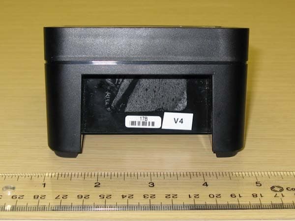
Click to zoom
Application Details
- Equipment Class
- DSS - Part 15 Spread Spectrum Transmitter
- Date of Grant
- Aug 12, 2010
- Application Purpose
- Original Equipment
- Date of Application
- Aug 12, 2010
- Equipment Note
- UNIFIED COMMUNICATION (UC) DEVICE WITH PSTN, USB AND 2 BLUETOOTH RADIOS
- Frequency Range
- 2402.00000000 - 2480.00000000
- Company
- HP Inc.
- Country
- United States
Documents & Files
Document Text
Text extracted from the exhibit documents filed with the FCC. Open a document above to read the original.
Users Manual
Plantronics Calisto P820/ P825(P820 + PA50)/ P830/ P835(P830 + PA50)/ P820-M/ P825-M(P820-M + PA50)/ P830-M/ P835(P830-M + PA50) Getting Started Refer to the safety instructions at the end of this guide prior to installation or use. For the full User Guide, visit www.plantronics.com/calisto800 1: Cables Analog telephone cable (P830/P830-M, P835/P835-M models only) USB cable to computer AC adapter (P830/P830-M, P835/P835-M models only))* *available as an optional accessory for P820/P825/P820- M/P825-M 2: Software Plantronics Software is Optional for versions Optimized for Microsoft Communicator (P820-M, P825-M, P830-M, P835-M), but allows you to use your Calisto with other PC softphones. Plantronics Software is Required for Standard UC versions (P820, P825, P830, P835). 1. Go to www.plantronics.com/calisto800 to download the software and check compatibility. 2. Go to Windows “Start” menu, select “Programs” and select “Plantronics Control Panel.” In Plantronics Control Panel, select your default softphone. 3: Setup To complete set-up, simply follow Calisto on-screen setup instructions. 4: Basic Features Talk/End key PC/ Mobile/ Landline icons indicate line selected for outgoing calls Audio key. Switches from the speakerphone to a headset (or wireless mic, see next page) and back. Mute key 3.5mm headset/headphone jacks PA50 Wireless Mic The PA50 wireless mic is included with the Calisto P825, P825-M, P835, P835-M speakerphone systems and is an optional accessory for the Calisto P820, P820-M, P830, and P830-M. The wireless mic provides unparalleled freedom of movement and optimal voice transmission. 1: Setup /!\ Disconnect all cables from the Calisto base. Insert wireless mic docking station firmly into the slots at the bottom of the base. Reconnect all cables. Place the wireless mic in the docking station and charge it for a minimum of 2 hours or until the Calisto screen indicates the mic is fully charged. 2: Wearing and Use The wireless mic can be worn on a collar or lapel, see diagram for optimal location. The wireless mic can also be placed flat on a table for flexible small group conferencing. It provides 360-degree microphone coverage. Talk Time: Up to 7 hours Maximum range: Up to 45 feet/12 meters 2: Features Once undocked, press the key on the wireless mic to replace the built-in speakerphone microphone. When the wireless mic is active, the {icon} is displayed on screen and the built-in speakerphone microphone is turned off. To transfer a call from the wireless mic to the speakerphone and back, press on the speakerphone. Talk/End Key: Press with one tap to answer or end a call. The key is green when you have an incoming call, red when you are on a call. Mute/Unmute Keys: Press red key on both sides. The keys light red when a call is muted. Warranty Warranty: Plantronics offers a two (2) year limited warranty. For full warranty details, conditions and technical assistance, please visit our website: www.plantronics.com/support Safety Instructions Please read the following safety and operational instructions before using your Calisto phone system. Please keep these instructions for your reference. When using this product, these basic safety precautions and warnings should be followed to reduce the risk of fire, electric shock, injury to persons and damage to property. /!\ This symbol identifies and alerts the user to the presence of important safety warnings. Operating, storage and charging temperature is 0°C to 40°C (32°F to 104°F). /!\ Warnings o Avoid using a telephone during an electrical storm. There may be a remote risk of electric shock from lightning. o Do not use the telephone to report a gas leak in the vicinity of the leak. o Plug the AC adapter into the outlet nearest the equipment that is easily accessible. o To reduce the risk of electric shock, explosion or fire, use only the AC adapter supplied by Plantronics to power the product. Do not use the adapter for any other purpose. Ensure that the voltage rating corresponds to the power supply you intend to use, for example 100-240 V; 50/60 Hz; 0.2 A. o Do not disassemble the AC adapter as this may expose you to dangerous voltages or other risks. Incorrect reassembly can cause electric shock or fire when the product is subsequently used. o Observe all signs and instructions regarding the use of an electrical device or RF radio product in designated areas, such as gas/refueling stations, hospitals, blasting areas, potentially explosive atmospheres, or aircraft. o Do not insert anything into the product because this may cause damage to the internal components or cause injury to you. o Avoid contact with liquids. Do not locate this product near water, for example, near a bathtub, or sink, in a wet basement, or near a swimming pool. o Discontinue use of product and contact Plantronics if the product or AC adapter overheats, has a damaged cord or plug, if the product has come into contact with liquids. o Use only those Plantronics products and accessories designed for use with this product. o CHILDREN. Never allow children to play with the product—small parts may be a choking hazard. o If you experience a skin irritation after using this product, discontinue use and contact Plantronics. o Exposure to high volume sound levels may cause temporary or permanent damage to your hearing. Although there is no single volume setting that is appropriate for everyone, you should always use this product with the volume set at moderate levels and avoid prolonged exposure to high volume sound levels. The louder the volume, the less time is required before your hearing could be affected. You may experience different sound levels when using this product with different devices. The device you use and its settings affect the level of sound you hear. If you experience hearing discomfort, you should stop using this product and have your hearing checked by your doctor. To protect your hearing when using a headset, some hearing experts suggest that you: …
Text truncated - open the document above for the full version.
Attestation Statements
Worldwide Headquarters 345 Encinal Street Santa Cruz, CA 95060 Date: August 2, 2010 Compliance Certification Services Certification Division 47173 Benicia Street Fremont, CA 94538, USA RE : Bluetooth Declaration Per FCC 15.247 Requirements To whom it may concern: Regarding FCC ID: AL8-P830, we, the undersigned, declare that the equipment complies with the Bluetooth CORE Specification 2.1 which includes: 1) a pseudorandom hopping sequence 2) equal on average channel use 3) a receiver with a compliant input bandwidth, based on the measured 20 dB emission bandwidth 4) a receiver with the ability to hop in synchronization with the transmitter 5) a frequency hopping system compliant with all pertinent requirements when presented with a lengthy data stream 6) a frequency hopping system compliant with the non-coordination requirement Sincerely, Peter Clark Compliance Engineering Manager
Cover Letter(s)
Worldwide Headquarters 345 Encinal Street Santa Cruz, CA 95060 August 2, 2010 Federal Communications Commission 7435 Oakland Mills Road Columbia MD 21046 Subject: Request for Long Term Confidentiality FCC ID: AL8-P830 To Whom It May Concern: Pursuant to the provisions of Sections 0.457 and 0.459 of the Commission’s rules (47 CFR §§ 0.457, 0.459), we are requesting the Commission to withhold the following attachments as confidential document from public disclosure indefinitely. Schematic Diagram Block Diagram Theory of Operation Above mentioned document contains detailed system and equipment description are considered as proprietary information in operation of the equipment. The public disclosure of above documents might be harmful to our company and would give competitor an unfair advantage in the market. Sincerely, Peter Clark Compliance Manager
Cover Letter(s)
Worldwide Headquarters 345 Encinal Street Santa Cruz, CA 95060 August 2, 2010 Federal Communications Commission 7435 Oakland Mills Road Columbia MD 21046 Subject: Request for Short Term Confidentiality FCC ID: AL8-P830 To Whom It May Concern: Pursuant to Public Notice DA 04-1705 of the Commission’s policy, in order to comply with the marketing regulations in 47 CFR §2.803 and the importation rules in 47 CFR §2.1204, while ensuring that business sensitive information remains confidential until the actual marketing of newly authorized devices. We are requesting the commission to grant short- term confidentiality request on the following attachments until January 15, 2011. External Photos Internal Photos Test Setup Photos User Manual It is our understanding that all measurement test reports, FCC ID label format and correspondent during certification review process cannot be granted as confidential documents and those information will be available for public review once the grant of equipment authorization is issued. Sincerely, Peter Clark Compliance Manager
Cover Letter(s)
Worldwide Headquarters 345 Encinal Street Santa Cruz, CA 95060 Date: August 2, 2010 Compliance Certification Services Certification Division 47173 Benicia Street Fremont, CA 94538, USA To whom it may concern: I, the undersigned, hereby authorize Ms. Claire Hoque/Application Examiner of Compliance Engineering Services, Inc., d.b.a. Compliance Certification Services and hereafter referred to as CCS, to act on our behalf in all manners relating to application for equipment authorization, including signing of all documents relating to these matters. Any and all acts carried out by Ms. Claire Hoque of CCS on our behalf shall have the same effect as acts of our own. I, the undersigned, hereby certify that we are not subject to a denial of federal benefits, that includes FCC benefits, pursuant to Section 5301 of the Anti-Drug Abuse Act of 1988, 21 U.S.C. 853(a). In authorizing CCS as our agent, we still recognize that we are responsible to: a) comply with the relevant provisions of the certification program; b) make all necessary arrangements for the conduct of the evaluation, including provision for examining documentation and access to all areas, records (including internal audit reports) and personnel for the purposes of evaluation (e.g. testing, inspection, assessment, surveillance, reassessment) and resolution of complaints; c) make claims regarding certification only in respect of the scope for which certification has been granted; d) do not use our product certification in such a manner as to bring the Certification Division into disrepute and not make any statement regarding our product certification which the Certification Division may consider misleading or unauthorized; Worldwide Headquarters 345 Encinal Street Santa Cruz, CA 95060 e) upon suspension or cancellation of certification, discontinue use of all advertising matter that contains any reference thereto and return any certification documents as required by the Certification Division; f) use certification only to indicate the products are certified as being in conformity with specified standards; g) endeavor to ensure that no certificate or report nor any part thereof is used in a misleading manner; h) ensure that any reference to our product certification in communication media such as documents, brochures or advertising, complies with the requirements of the Certification Division; i) keep a record of all complaints made known to the us relating to the product’s compliance with requirements of the relevant standard and to make these records available to the Certification Division when requested; j) take appropriate action with respect to such complaints and any deficiencies found in products or services that affect compliance with the requirements for certification; k) document the actions taken. This authorization is valid until further written notice from the applicant. Sincerely, Peter Clark Compliance Engineering Manager
External Photos
AL8-P830 External Photos TOP BOTTOM Front Back Left Right
ID Label/Location Info
AL8-P830 Label and Location
Internal Photos
AL8-P830 Internal Photos PCB Installed PCB Top with shield PCB Top No Shield PCB Bottom
Test Report
FCC CFR47 PART 15 SUBPART C INDUSTRY CANADA RSS-210 ISSUE 7 CERTIFICATION TEST REPORT FOR UNIFIED COMMUNICATION (UC) DEVICE WITH PSTN, USB AND 2 BLUETOOTH RADIOS MODEL NUMBER: P820, P820-M, P830, P830-M FCC ID: AL8-P820, AL8-P830 IC: 457A-P820, 457A-P830 REPORT NUMBER: 10U13293-1, Revision A ISSUE DATE: AUGUST 10, 2010 Prepared for PLANTRONICS, INC. 345 ENCINAL STREET SANTA CRUZ, CA 95060, U.S.A Prepared by COMPLIANCE CERTIFICATION SERVICES 47173 BENICIA STREET FREMONT, CA 94538, U.S.A. TEL: (510) 771-1000 FAX: (510) 661-0888 * Models differences are contained in the body of this report REPORT NO: 10U13293-1A DATE: August 10, 2010 FCC ID: AL8-P820, AL8-P830 IC: 457A-P820, 457A-P830 Page 2 of 194 COMPLIANCE CERTIFICATION SERVICES FORM NO: CCSUP4701C 47173 BENICIA STREET, FREMONT, CA 94538, USA TEL: (510) 771-1000 FAX: (510) 661-0888 This report shall not be reproduced except in full, without the written approval of CCS. Revision History Rev. Issue Date Revisions Revised By -- 07/26/10 Initial Issue F. Ibrahim A 08/10/10 Revised RBW and VBW in the Hopping Frequency Separation sections, revised the setup diagram, I/O list and peripherals list, and revised the average time of occupancy for 8PSK modulation. F. Ibrahim REPORT NO: 10U13293-1A DATE: August 10, 2010 FCC ID: AL8-P820, AL8-P830 IC: 457A-P820, 457A-P830 Page 3 of 194 COMPLIANCE CERTIFICATION SERVICES FORM NO: CCSUP4701C 47173 BENICIA STREET, FREMONT, CA 94538, USA TEL: (510) 771-1000 FAX: (510) 661-0888 This report shall not be reproduced except in full, without the written approval of CCS. TABLE OF CONTENTS 1. ATTESTATION OF TEST RESULTS.................................................................................... 5 2. TEST METHODOLOGY ........................................................................................................ 6 3. FACILITIES AND ACCREDITATION.................................................................................... 6 4. CALIBRATION AND UNCERTAINTY .................................................................................. 6 4.1. MEASURING INSTRUMENT CALIBRATION ............................................................... 6 4.2. SAMPLE CALCULATION.............................................................................................. 6 4.3. MEASUREMENT UNCERTAINTY................................................................................ 6 5. EQUIPMENT UNDER TEST ................................................................................................. 7 5.1. DESCRIPTION OF EUT................................................................................................ 7 5.2. MODEL(S) DIFFERENCES .......................................................................................... 7 5.3. MAXIMUM OUTPUT POWER....................................................................................... 7 5.4. DESCRIPTION OF AVAILABLE ANTENNAS............................................................... 8 5.5. SOFTWARE AND FIRMWARE..................................................................................... 8 5.6. WORST-CASE CONFIGURATION AND MODE .......................................................... 8 5.7. DESCRIPTION OF TEST SETUP................................................................................. 9 6. TEST AND MEASUREMENT EQUIPMENT ....................................................................... 11 7. ANTENNA PORT TEST RESULTS (MICROPHONE MODULE)........................................ 12 7.1. BASIC DATA RATE GFSK MODULATION................................................................. 12 7.1.1. 20 dB AND 99% BANDWIDTH............................................................................ 12 7.1.2. HOPPING FREQUENCY SEPARATION ............................................................ 19 7.1.3. NUMBER OF HOPPING CHANNELS................................................................. 21 7.1.4. AVERAGE TIME OF OCCUPANCY.................................................................... 26 7.1.5. OUTPUT POWER ............................................................................................... 29 7.1.6. AVERAGE POWER ............................................................................................ 33 7.1.7. CONDUCTED SPURIOUS EMISSIONS............................................................. 34 7.2. ENHANCED DATA RATE 8PSK MODULATION........................................................ 43 7.2.1. 20 dB AND 99% BANDWIDTH............................................................................ 43 7.2.2. HOPPING FREQUENCY SEPARATION ............................................................ 50 7.2.3. NUMBER OF HOPPING CHANNELS................................................................. 52 7.2.4. AVERAGE TIME OF OCCUPANCY.................................................................... 57 7.2.5. OUTPUT POWER ............................................................................................... 60 7.2.6. AVERAGE POWER ............................................................................................ 64 7.2.7. CONDUCTED SPURIOUS EMISSIONS............................................................. 65 8. ANTENNA PORT TEST RESULTS (MOBILE PHONE MODULE)..................................... 74 8.1. BASIC DATA RATE GFSK MODULATION................................................................. 74 8.1.1. 20 dB AND 99% BANDWIDTH............................................................................ 74 8.1.2. HOPPING FREQUENCY SEPARATION ............................................................ 81 REPORT NO: 10U13293-1A DATE: August 10, 2010 FCC ID: AL8-P820, AL8-P830 IC: 457A-P820, 457A-P830 Page 4 of 194 COMPLIANCE CERTIFICATION SERVICES FORM NO: CCSUP4701C 47173 BENICIA STREET, FREMONT, CA 94538, USA TEL: (510) 771-1000 FAX: (510) 661-0888 This report shall not be reproduced except in full, without the written approval of CCS. 8.1.3. NUMBER OF HOPPING CHANNE…
Text truncated - open the document above for the full version.
Test Setup Photos
REPORT NO: 10U13293-1A DATE: August 10, 2010 FCC ID: AL8-P820, AL8-P830 IC: 457A-P820, 457A-P830 Page 191 of 194 COMPLIANCE CERTIFICATION SERVICES FORM NO: CCSUP4701C 47173 BENICIA STREET, FREMONT, CA 94538, USA TEL: (510) 771-1000 FAX: (510) 661-0888 This report shall not be reproduced except in full, without the written approval of CCS. 18. SETUP PHOTOS ANTENNA PORT CONDUCTED RF MEASUREMENT SETUP For MIC 2) For Mobile Phone ANTENNA PORT CONDUCTED PHOTO ANTENNA PORT CONDUCTED PHOTO REPORT NO: 10U13293-1A DATE: August 10, 2010 FCC ID: AL8-P820, AL8-P830 IC: 457A-P820, 457A-P830 Page 192 of 194 COMPLIANCE CERTIFICATION SERVICES FORM NO: CCSUP4701C 47173 BENICIA STREET, FREMONT, CA 94538, USA TEL: (510) 771-1000 FAX: (510) 661-0888 This report shall not be reproduced except in full, without the written approval of CCS. RADIATED RF MEASUREMENT SETUP RADIATED FRONT PHOTO RADIATED BACK PHOTO REPORT NO: 10U13293-1A DATE: August 10, 2010 FCC ID: AL8-P820, AL8-P830 IC: 457A-P820, 457A-P830 Page 193 of 194 COMPLIANCE CERTIFICATION SERVICES FORM NO: CCSUP4701C 47173 BENICIA STREET, FREMONT, CA 94538, USA TEL: (510) 771-1000 FAX: (510) 661-0888 This report shall not be reproduced except in full, without the written approval of CCS. POWERLINE CONDUCTED EMISSIONS MEASUREMENT SETUP LINE CONDUCTED FRONT PHOTO REPORT NO: 10U13293-1A DATE: August 10, 2010 FCC ID: AL8-P820, AL8-P830 IC: 457A-P820, 457A-P830 Page 194 of 194 COMPLIANCE CERTIFICATION SERVICES FORM NO: CCSUP4701C 47173 BENICIA STREET, FREMONT, CA 94538, USA TEL: (510) 771-1000 FAX: (510) 661-0888 This report shall not be reproduced except in full, without the written approval of CCS. END OF REPORT LINE CONDUCTED BACK PHOTO
Contact Information
Applicant
Ismael Talancon(Manager, Technical Compliance)
Test Firm
Compliance Certification ServicesThu Chan
Technical Specifications
| # | Rule Parts | Frequency Range | Power Output |
|---|---|---|---|
| 2 | 15C | 2.40 GHz - 2.48 GHz | 2.70 mW |
Other Applications from HP Inc.
AL8-PWPTF620P
Feb 03, 2026Wireless Charge Stand
Equipment Class
DCD - Part 15 Low Power Transmitter Below 1705 kHzAL8-PBF620F
Jan 23, 2026Bluetooth Headset
Equipment Class
DTS - Digital Transmission SystemAL8-PBVOYX2
Jun 20, 2024Bluetooth Base
Equipment Class
DTS - Digital Transmission System
AL8-VF2R
Mar 07, 2024Wireless Bluetooth Earphones
Equipment Class
DTS - Digital Transmission System
AL8-CBVS1
Oct 16, 2023Wireless Charge Stand
Equipment Class
DXX - Part 15 Low Power Communication Device Transmitter