AL8-VS80TBluetooth Stereo Headset
HP Inc.
Click to zoom
Application Details
- Equipment Class
- DTS - Digital Transmission System
- Date of Grant
- Dec 25, 2022
- Application Purpose
- Original Equipment
- Date of Application
- Dec 25, 2022
- Equipment Note
- Bluetooth Stereo Headset
- Frequency Range
- 2402.00000000 - 2480.00000000
- Company
- HP Inc.
- Country
- United States
Documents & Files
Document Text
Text extracted from the exhibit documents filed with the FCC. Open a document above to read the original.
Users Manual
Poly Voyager Surround 80 Bluetooth stereo headset User Guide DRAFT – CONFIDENTIAL DO NOT SHARE Contents Overview3 Headset3 USB Bluetooth adapter4 Connect and pair5 Pair to mobile device5 Connect to PC5 Configure USB adapter for streaming media6 Pair BT700 USB adapter again6 Fit and charge7 Fit7 Charge7 Check headset battery status7 Load software8 Update your Poly device8 The basics9 Touch control on right earcup9 Power on/off9 Adjust volume9 Play or pause music9 Track forward10 Track backward10 ANC and Transparency Mode10 ANC and Transparency Mode settings11 Voice assistant (smartphone feature)11 Use sensors11 Make/Take/End Calls13 Make a call13 Answer or end a call13 Hold call13 Switch between calls (flash)13 Mute 13 Answer a second call13 Redial last outgoing call (smartphone feature)13 Launch Microsoft Teams (Teams model only)13 More Features15 Customize your headset15 Stream audio with USB-C to 3.5mm cable15 What's in the box16 Support17 Overview Headset ANC / Transparency Your headset has touch control on the right earcup. Use swipe and tap gestures for call and media control. Note: Swipe and tap gestures do not work when connected to PC with USB-C cable. Use your PC interface for call and media control. Volume control •Swipe up/down to adjust volume Call control •Tap to answer/end call Interact with Microsoft Teams (Teams model only, Teams app required) •Tap to interact when not on a call Audio control* •Tap to play/pause •Swipe to track forward/backward ANC (Active Noise Canceling) and Transparency Mode LEDs/Online indicator Mute/unmute Power Bluetooth ® pairing Charge port Note: *Functionality varies by application. May not function with web-based apps. DRAFT – CONFIDENTIAL DO NOT SHARE 3 USB Bluetooth adapter Your high-fidelity Bluetooth USB adapter comes pre-paired to your Poly device. Plug it into your computer to connect to high-fidelity computer audio. Note: Adapter's USB connection and design may vary, but function is the same. Standard LEDs USB LEDsWhat they mean Flashing red and bluePairing Solid blueDevice connected Flashing blueOn a call Solid redMute active Flashing purpleStreaming media from computer LEDs when Microsoft Teams* is detected USB LEDsWhat they mean Flashing red and bluePairing Solid purpleMicrosoft Teams connected Flashing blueOn a call Solid redMute active Pulsing purpleMicrosoft Teams notification Note: *Requires Microsoft Teams desktop application. DRAFT – CONFIDENTIAL DO NOT SHARE 4 Connect and pair Pair to mobile device 1 To put your headset in pair mode, slide and hold the Power switch away from the off position until you hear "pairing" and the headset LEDs flash blue and white. :02 “Pairing” Blutooth Headphones Computer Camera 2Activate Bluetooth on your phone and set it to search for new devices. •iPhone Settings > Bluetooth > On* •Android Settings > Bluetooth On > Scan for devices* Note: *Menus may vary by device. 3Select “Poly VSurround 80.” Once successfully paired, you hear “pairing successful” and the headset LEDs stop flashing. Note: Your headset can pair with up to 8 devices but only maintain 2 connections simultaneously; this includes the Bluetooth adapter. Connect to PC Your Bluetooth USB adapter provides the best connection, softphone functionality and acoustic sound quality through your headset. The adapter comes pre-paired to your headset. 1Turn on your headset and insert the Bluetooth USB adapter into your laptop or PC. 2The USB adapter LED flashes and then turns solid to indicate the headset is connected to the USB adapter. If you are wearing your headset you hear “PC connected” to indicate the connection has been established. When on a call, the LED on the USB adapter flashes blue. When not on a call the LED is solid. 3Load Poly Lens Desktop App by visiting poly.com/lens. This allows you to customize your headset behavior through advanced settings and options. DRAFT – CONFIDENTIAL DO NOT SHARE 5 Configure USB adapter for streaming media Your high-fidelity Bluetooth USB adapter comes ready to take calls. To streaming media, configure your Bluetooth USB adapter. Windows 1To configure your Bluetooth USB adapter for streaming media in your PC, go to Start menu > Control Panel > Sound > Playback tab. Select Poly BT700 set it as the Default Device and click OK. 2To pause music when you place or receive calls, go to Start menu > Control Panel > Sound > Communications tab and select the desired parameter. Mac 1To configure your Bluetooth USB adapter for streaming media on your Mac, go to System Preferences > Sound. On both the Input and Output tabs, select Poly BT700. Pair BT700 USB adapter again Your USB adapter requires Poly Lens Desktop App to pair to a Poly audio device. Download: poly.com/lens. Note: Adapter design varies by USB connection. 1Insert the high-fidelity Bluetooth USB adapter into your laptop or computer and wait for your computer to recognize it. 2Put your Poly audio device in pair mode. 3Launch Poly Lens Desktop App and navigate to Poly BT700. 4Put your Bluetooth USB adapter into pair mode by selecting "Pair new device" on the adapter's main page or overflow menu. Your adapter flashes red and blue. Pairing is successful when you hear "pairing successful" and "PC connected" and the Bluetooth USB adapter LED is solid. DRAFT – CONFIDENTIAL DO NOT SHARE 6 Fit and charge Fit Important: Headset microphones are on the front of your earcups. For best call audio, ensure your headset is worn correctly. R L Charge Charge your headset using the USB-C cable. The headset LEDs flash when charging. It takes approximately 1 hour to fully charge your headset. The LEDs turn off once charging is complete. Note: The USB-C cable plugs into a computer or wall charger's USB port. Headset LEDsWhat they mean OffCharging complete Battery high Battery medium Battery low Battery critical Check headset battery status Check your headset battery status: • With your headset inactive, slide and release the Power switch away from the off position. Listen t…
Text truncated - open the document above for the full version.
Users Manual
Regulatory Compliance Information United States/Puerto Rico BC 5011639 I.T.E 81242 Declaration of Conformity/FCC Regulatory Information We Plantronics Inc, 345 Encinal Street Santa Cruz, California, 95060 USA (800) 544-4660 declare under our sole responsibility that the products MODELS VS80T / BT700 / BT700C comply with Part 15 of the FCC Rules. Operation is subject the following two conditions: (1) this device may not cause harmful interference, and (2) this device must accept any interference received, including interference that may cause undesired operation. Note: This equipment has been tested and found to comply with the limits for a Class B digital device, pursuant to part 15 of the FCC Rules. These limits are designed to provide reasonable protection against harmful interference in a residential installation. This equipment generates, uses, and can radiate radio frequency energy and, if not installed and used in accordance with the instructions, may cause harmful interference to radio communications. However, there is no guarantee that interference will not occur in a particular installation. If this equipment does cause harmful interference to radio or television reception, which can be determined by turning the equipment off and on, the user is encouraged to try to correct the interference by one or more of the following measures: 1. Reorient or relocate the receiving antenna. 2. Increase the separation between the equipment and receiver. 3. Connect the equipment into an outlet on another circuit. 4. Consult the dealer or an experienced radio/TV technician for help. Changes or modifications not expressly approved by the party responsible for compliance could void the user’s authority to operate the equipment. Taiwan 根據NCC低功率管理辦法規定:取得審驗證明之低功率射頻器材,非經核准,公司、商號或使用 者均不得擅自變更頻率、加大功率或變更原設計之特性及功能。 低功率射頻器材之使用不得 影響飛航安全及干擾合法通信;經發現有干擾現象時,應立即停用,並改善至無干擾時方得繼 續使用。 前述合法通信,指依電信管理法規定作業之無線電通信。 低功率射頻器材須忍受合法通信或工業、科學及醫療用電波輻射性電機設備之干擾。 Thailand “เครื่องโทรคมน าคมและอุปกร ณนี้ มีความสอ ดคล องตามมาตรฐานทางเทคนิค เลขที่.........” “เคร ื่องโทรคมน าคมและอุปกร ณนี้ มีความสอ ดคล องตามขอกํ าหนดของ กทช.” or MFi Made for iPhone 11 Pro Max, iPhone 11 Pro, iPhone 11, iPhone XS Max, iPhone XS, iPhone XR , iPhone X, iPhone 8 Plus, iPhone 8, iPhone 7 Plus, iPhone 7, iPhone SE, iPhone 6s Plus, iPhone 6s. FreeRTOS software Permission is hereby granted, free of charge, to any person obtaining a copy of this FreeRTOS software and associated documentation files (the “Software”), to deal in the Software without restriction, including without limitation the rights to use, copy, modify, merge, publish, distribute, sublicense, and/or sell copies of the Software, and to permit persons to whom the Software is furnished to do so, subject to the following conditions: The above copyright notice and this permission notice shall be included in all copies or substantial portions of the Software. THE SOFTWARE IS PROVIDED “AS IS”, WITHOUT WARRANTY OF ANY KIND, EXPRESS OR IMPLIED, INCLUDING BUT NOT LIMITED TO THE WARRANTIES OF MERCHANTABILITY, FITNESS FOR A PARTICULAR PURPOSE AND NONINFRINGEMENT. IN NO EVENT SHALL THE AUTHORS OR COPYRIGHT HOLDERS BE LIABLE FOR ANY CLAIM, DAMAGES OR OTHER LIABILITY, WHETHER IN AN ACTION OF CONTRACT, TORT OR OTHERWISE, ARISING FROM, OUT OF OR IN CONNECTION WITH THE SOFTWARE OR THE USE OR OTHER DEALINGS IN THE SOFTWARE. Exposure to RF Radiation The internal wireless radio operates within the guidelines found in radio frequency safety standards and recommendations, which reflect the consensus of the scientific community. Independent studies have shown that the internal wireless radio is safe for use by consumers. Visit plantronics.com for more information. In order to comply with FCC and IC RF Exposure requirements, the base must be installed and operated such that a minimum separation distance of 20 cm is maintained between the base and all persons during normal operation. This equipment complies with FCC radiation exposure limits set forth for an uncontrolled environement. NOTE: Modifications not expressly approved by Plantronics, Inc. could void the user’s authority to operate the equipment. Canada CAN ICES-003 (B)/NMB-003(B) C AN RSS-216 /CRN-216 ISED Canada Regulatory Information This device complies with ISED licence-exempt RSS standard(s). Operation is subject to the following two conditions: (1) this device may not cause interference, and (2) this device must accept any interference, including interference that may cause undesired operation of the device. Le présent appareil est conforme aux CNR d’ISED applicables aux appareils radio exempts de licence. L’exploitation est autorisée aux deux conditions suivantes : (1) l’appareil ne doit pas produire de brouillage, et (2) l’utilisateur de l’appareil doit accepter tout brouillage radioélectrique subi, même si le brouillage est susceptible d’en compromettre le fonctionnement. This equipment complies with ISED radiation exposure limits set forth for an uncontrolled environment. Cet équipement est conforme aux limites d’exposition de radiation ISED énoncés pour un environnement non contrôlé. Australia/New Zealand R-NZ Brazil Este equipamento não tem direito à proteção contra interferência prejudicial e não pode causar interferência em sistemas devidamente autorizados. Modelos: VS80T HHHHH-AA-FFFFF Argentina C-xxxxx China 型号核准代码显示在产品标签和产品本体上 Europe Energy efficiency – EuP framework Directive 2005/32/EC and implementing measure 1275/2008 incorporating commission regulation 801/2013: Once the headset battery is fully charged the product enters a networked standby mode. The period of time taken to enter this mode depends on how long the battery takes to fully charge. In networked standby mode the product consumes x.x Watts. The wireless network port(s) of this product are designed to be always active. Japan VCCI Class B statement: この装置は、クラスB機器です。この装置は、住宅環境で使用することを目的とし ていますが、この装置がラジオやテレビジョン受信機に近接して使用されると、受 信障害を引き起こすことがあります。 取扱説明書に従って正しい取り扱いをして下さい。 VCCI-B R …
Text truncated - open the document above for the full version.
Cover Letter(s)
Confidentiality Request Letter Federal Communications Commission Authorization and Evaluation Division FCC ID: AL8-VS80T Pursuant to Sections 0.457 and 0.459 of the Commission’s Rules, we hereby request confidential treatment of information accompanying this application as outlined below: 1. Block Diagram 2. Schematics 3. Operational Description In addition to above documents, in order to avoid premature release of sensitive information prior to marketing or release of the product to the public, we request the following documents contained in this certification application be temporarily withheld from public disclosure for an initial period of 180 days: 1. External Photos 2. Internal Photos 3. Test Setup Photos 4. User Manual The above materials contain trade secrets and proprietary information not customarily released to the public. The public disclosure of these matters might be harmful to the applicant and provide unjustified benefits to its competitors. The applicant understands that pursuant to Rule 0.457, disclosure of this application and all accompanying documentation will not be made before the date of the Grant for this application. Sincerely, _____________ ____ Name: Mark Lawson Title: Director, Global Compliance Date: 2022-12-12
Cover Letter(s)
Declaration of Authorization We Name: Plantronics, Inc. Address: 345 Encinal Street, Santa Cruz, CA 95060 USA Declare that: Name Representative of agent: Marlin Chen Agent Company name: MRT Technology (Suzhou) Co., Ltd Address: D8 Building, Youxin Industrial Park, No.2 Tian'edang Rd., Wuzhong Economic Development Zone City: Suzhou Country: China is authorized to apply for FCC Certification of the following product(s): Product: Bluetooth Stereo Headset Brand Name: plantronics FCC ID: AL8-VS80T Model No.: VS80T Sincerely, ___________ _____ Name: Mark Lawson Title: Director, Global Compliance Date: 2022-12-12
Cover Letter(s)
Declaration of Conformity Federal Communications Commission Authorization and Evaluation Division F F C C C C I I D D : : A A L L 8 8 - - V V S S 8 8 0 0 T T Please be notified that we, the undersigned, Plantronics, Inc. declares that the product which bears the above FCC ID is also compliant with the FCC requirements for sDOC. And the sDOC procedure shall be carried out prior to marketing the device in the US. Sincerely, ________________ _ Name: Mark Lawson Title: Director, Global Compliance Date: 2022-12-12
External Photos
Report No.: 2211RSU003-UE 1 of 5 EUT External Photograph (1) EUT Photo (2) EUT Photo Report No.: 2211RSU003-UE 2 of 5 (3) EUT Photo (4) EUT Photo Report No.: 2211RSU003-UE 3 of 5 (5) EUT Photo (6) EUT Photo Report No.: 2211RSU003-UE 4 of 5 (7) EUT Photo (8) EUT Photo Report No.: 2211RSU003-UE 5 of 5 (9) EUT Photo
ID Label/Location Info
27 Oct 13, 2021 Compliance Marks,LASER, Lark Chase Bailey 221000-01 Laser Markings 1:1 scale LEFT SPEAKER PLATE FRONT BACK Made in Mexico XXX-XXXXXX Model: VS80T ANATEL: HHHHH-AA-FFFFF FCC ID: AL8-VS80T IC: 457A-VS80T S/N: XXXXXX FH MY Input: 5V DC 1000mA MAX C-XXXXX CCAXXXXXXXXXXX CMIIT ID: XXXXXXXXXX R-NZ RIGHT SPEAKER PLATE FRONT BACK IS 616/IEC 60065 R-41177024 www.bis.gov.in Made in Mexico XXX-XXXXXX Model: VS80T ANATEL: HHHHH-AA-FFFFF FCC ID: AL8-VS80T IC: 457A-VS80T S/N: XXXXXX FH MY Input: 5V DC 1000mA MAX C-XXXXX CCAXXXXXXXXXXX CMIIT ID: XXXXXXXXXX R-NZ IS 616/IEC 60065 R-41177024 www.bis.gov.in
Internal Photos
Report No.: 2211RSU003-UE 1 of 9 EUT Internal Photograph (1) EUT Photo (2) EUT Photo Report No.: 2211RSU003-UE 2 of 9 (3) EUT Photo (L) (4) EUT Photo (L) Report No.: 2211RSU003-UE 3 of 9 (5) EUT Photo (L) (6) EUT Photo (L) Report No.: 2211RSU003-UE 4 of 9 (7) EUT Photo (R) (8) EUT Photo (R) Report No.: 2211RSU003-UE 5 of 9 (9) EUT Photo (R) (10) EUT Photo (R) Report No.: 2211RSU003-UE 6 of 9 (11) EUT Photo (R) (12) EUT Photo (R) Report No.: 2211RSU003-UE 7 of 9 (13) EUT Photo (R) (14) EUT Photo (R) Report No.: 2211RSU003-UE 8 of 9 (15) EUT Photo (R) (16) EUT Photo (R) Report No.: 2211RSU003-UE 9 of 9 (17) EUT Photo (R)
RF Exposure Info
MRT Technology (Suzhou) Co., Ltd Report No.: 2211RSU003-U3 Phone: +86-512-66308358 Report Version: V01 Web: www.mrt-cert.com Issue Date: 2022-12-22 Template Version:0.0 1 of 46 SAR MEASUREMENT REPORT FCC ID: AL8-VS80T Applicant: Plantronics, Inc. Product: Bluetooth Stereo Headset Model No.: VS80T Brand Name: plantronics FCC Rule Part(s): FCC 47 CFR Part 2.1093 Result: Complies Received Date: 2022-11-02 Test Date: 2022-12-10 Reviewed By: Vincent Yu Approved By: Robin Wu The test results relate only to the samples tested. This equipment has been shown to be capable of compliance with the applicable technical standards as indicated in the measurement report and was tested in accordance with the measurement procedures specified in IEEE1528, KDB 447498 and KDB 865664. Test results reported herein relate only to the item(s) tested. The test report shall not be reproduced except in full without the written approval of MRT Technology (Suzhou) Co., Ltd. Report No.: 2211RSU003-U3 2 of 46 Revision History Report No. Version Description Issue Date Note 2211RSU003-U3 Rev. 01 Initial Report 2022-12-22 Valid Report No.: 2211RSU003-U3 3 of 46 CONTENTS Description Page 1. General Information ................................................................................................................................. 5 1.1. Applicant ........................................................................................................................................ 5 1.2. Manufacturer .................................................................................................................................. 5 1.3. Testing Facility ............................................................................................................................... 5 1.4. Product Information ........................................................................................................................ 6 1.5. Radio Specification under Test ...................................................................................................... 6 1.6. Antennas Details ............................................................................................................................ 6 2. Summary of Test Result .......................................................................................................................... 7 2.1. Test Standards ............................................................................................................................... 7 2.2. Environment Condition ................................................................................................................... 7 2.3. RF Exposure Limits ........................................................................................................................ 7 2.4. Test Result Summary .................................................................................................................... 8 3. Specific Absorption Rate (SAR) .............................................................................................................. 9 3.1. Introduction .................................................................................................................................... 9 3.2. Definition ........................................................................................................................................ 9 4. DASY6 Measurement System................................................................................................................ 10 4.1. Introduction .................................................................................................................................. 10 4.2. DASY6 Measurement System Diagram ...................................................................................... 10 4.3. System Components Details........................................................................................................ 11 5. The SAR Measurement Procedure ....................................................................................................... 22 5.1. Measurement Process Diagram .................................................................................................. 22 5.2. Test Position Definition ................................................................................................................ 23 5.3. Test Procedure ............................................................................................................................ 26 6. System Verificaiton ................................................................................................................................ 29 6.1. Tissue Check ............................................................................................................................... 29 6.2. System Check .............................................................................................................................. 32 7. Analysis and Results ............................................................................................................................. 34 7.1. Antennna Location ....................................................................................................................... 34 7.2. Conducted Power ........................................................................................................................ 34 7.3. SAR Exclusion Analysis ............................................................................................................... 35 7.4. SAR Test Results ......................................................................................................................... 36 8. Simultaneous Transmission Analysis .................................................................................................. 37 Report No.: 2211RSU003-U3 4 of 46 9. Test Equipment Used ..........................................................................…
Text truncated - open the document above for the full version.
Test Report
MRT Technology (Suzhou) Co., Ltd Report No.: 2211RSU003-U2 Phone: +86-512-66308358 Report Version: V01 Web: www.mrt-cert.com Issue Date: 2022-12-22 Template Version:0.0 1 of 59 RF MEASUREMENT REPORT FCC ID: AL8-VS80T Applicant: Plantronics, Inc. Product: Bluetooth Stereo Headset Model No.: VS80T Brand Name: plantronics FCC Classification: Digital Transmission System (DTS) FCC Rule Part(s): Part 15 Subpart C (Section 15.247) Result: Complies Received Date 2022-11-02 Test Date: 2022-11-07 ~ 2022-12-13 Reviewed By: Vincent Yu Approved By: Robin Wu The test results relate only to the samples tested. This equipment has been shown to be capable of compliance with the applicable technical standards as indicated in the measurement report and was tested in accordance with the measurement procedures specified in ANSI C63.10-2013. Test results reported herein relate only to the item(s) tested. The test report shall not be reproduced except in full without the written approval of MRT Technology (Suzhou) Co., Ltd. Report No.: 2211RSU003-U2 2 of 59 Revision History Report No. Version Description Issue Date Note 2211RSU003-U2 Rev. 01 Initial Report 2022-12-22 Valid Report No.: 2211RSU003-U2 3 of 59 CONTENTS Description Page 1. General Information ................................................................................................................................ 5 1.1. Applicant ...................................................................................................................................... 5 1.2. Manufacturer ................................................................................................................................ 5 1.3. Testing Facility ............................................................................................................................. 5 1.4. Product Information ...................................................................................................................... 6 1.5. Radio Specification under Test .................................................................................................... 6 1.6. Working Frequencies ................................................................................................................... 6 2. Test Configuration ................................................................................................................................... 7 2.1. Test Mode .................................................................................................................................... 7 2.1. Test System Connection Diagram................................................................................................ 7 2.2. Test Software ............................................................................................................................... 7 2.3. Applied Standards ........................................................................................................................ 8 2.4. Test Environment Condition ......................................................................................................... 8 3. Antenna Requirements ........................................................................................................................... 9 4. Measuring Instrument ........................................................................................................................... 10 5. Decision Rules and Measurement Uncertainty .................................................................................. 11 5.1. Decision Rules ............................................................................................................................ 11 5.2. Measurement Uncertainty ........................................................................................................... 11 6. Test Result .............................................................................................................................................. 12 6.1. Summary .................................................................................................................................... 12 6.2. 6dB Bandwidth Measurement .................................................................................................... 13 6.2.1. Test Limit .................................................................................................................................... 13 6.2.2. Test Procedure ........................................................................................................................... 13 6.2.3. Test Setting ................................................................................................................................ 13 6.2.4. Test Setup .................................................................................................................................. 13 6.2.5. Test Result ................................................................................................................................. 13 6.3. Output Power Measurement ...................................................................................................... 14 6.3.1. Test Limit .................................................................................................................................... 14 6.3.2. Test Procedure ........................................................................................................................... 14 6.3.3. Test Setting ................................................................................................................................ 14 6.3.4. Test Setup .................................................................................................................................. 14 6.3.5. Test Result ................................................................................................................................. 14 6.4. Power Spectral Density Measurement ...…
Text truncated - open the document above for the full version.
Test Report
Return Loss and Impedance Indicated By Head Tissue Meas. Items Original Value Current Value Deviation Return Loss(dB) -29.0 -27.73 -4.38% Impedance 53.7Ω - 0.01jΩ 51.46Ω - 1.61Ω -2.24Ω Real part -1.60Ω Imaginary part Test Date: 2022/05/18
Test Report
SCZ EMC LAB 10/19//2022 Lark (VS80T) Headset Power Output and Antenna Gain Antenna operating band: 2402 - 2480 MHz Antenna type: Inverted-F Connector Type: None – not removable Peak gain (directional): -0.81 dBi maximum on artificial head at 2402 MHz, and -1.78dBi maximum in free space ANTENNA GAIN PATTERNS: All Antenna Gain Patterns are derived from the measurements taken for power output and compared to conducted power measurements taken from the same device. HEAD Channel 0 = 2402MHz – Conducted power = 12.8 dBm Max Gain = -0.81 dBi Channel 39 = 2441MHz – Conducted power = 12.9 dBm Max Gain = -1.12 dBi Channel 78 = 2480MH z– Conducted power = 13.0 dBm Max Gain = -4.23 dBi FREE SPACE Channel 0 = 2402MHz – Conducted power = 12.8 dBm Max Gain = -1.78 dBi Channel 39 = 2441MHz – Conducted power = 12.9 dBm Max Gain = -3.35 dBi Channel 78 = 2480MH z– Conducted power = 13.0 dBm Max Gain = -4.95 dBi POWER OUTPUT PATTERNS (ON HEAD): All power output patters were run using the greater circle meathod at 15 degree increments, with measurement taken for both horizontal and vertical polarizations at Low (CH0-2402 MHz), Middle (CH39-2441 MHz) and High (CH78-2480 MHz) portions of the overal bluetooth band. This was accomplished by setting the device in CW output mode at it’s highest power setting. This first set of patterns are with Lark on a SAM (Semi-Anthropomorphic) Head that represents ‘loading’ as if in actual use. EUT Serial # 0001JA Channel 0 (2402 MHz) Max power 11.99 dBm EUT Serial # 0001JA Channel 39 (2441 MHz) Max power 11.78 dBm EUT Serial # 0001JA Channel 78 (2480 MHz) Max power 8.77 dBm ANTENNA GAIN PATTERNS (ON HEAD): All Antenna Gain Patterns are derived from the measurements taken for power output and compared to conducted power measurements taken from the same device. Channel 0 = 2402MHz – …
Text truncated - open the document above for the full version.
Contact Information
Applicant
Richard Tarsio(US/CAN TRSE Worldwide Technical Regulations)
Test Firm
MRT Technology (Suzhou) Co., Ltd.Mr. Marlin Chen
[email protected]8651266308358
Technical Specifications
| # | Rule Parts | Frequency Range | Power Output |
|---|---|---|---|
| 1 | 15C | 2.40 GHz - 2.48 GHz | 7.60 mW |
Other Applications from HP Inc.
AL8-PWPTF620P
Feb 03, 2026Wireless Charge Stand
Equipment Class
DCD - Part 15 Low Power Transmitter Below 1705 kHzAL8-PBF620F
Jan 23, 2026Bluetooth Headset
Equipment Class
DTS - Digital Transmission SystemAL8-PBVOYX2
Jun 20, 2024Bluetooth Base
Equipment Class
DTS - Digital Transmission System
AL8-VF2R
Mar 07, 2024Wireless Bluetooth Earphones
Equipment Class
DTS - Digital Transmission System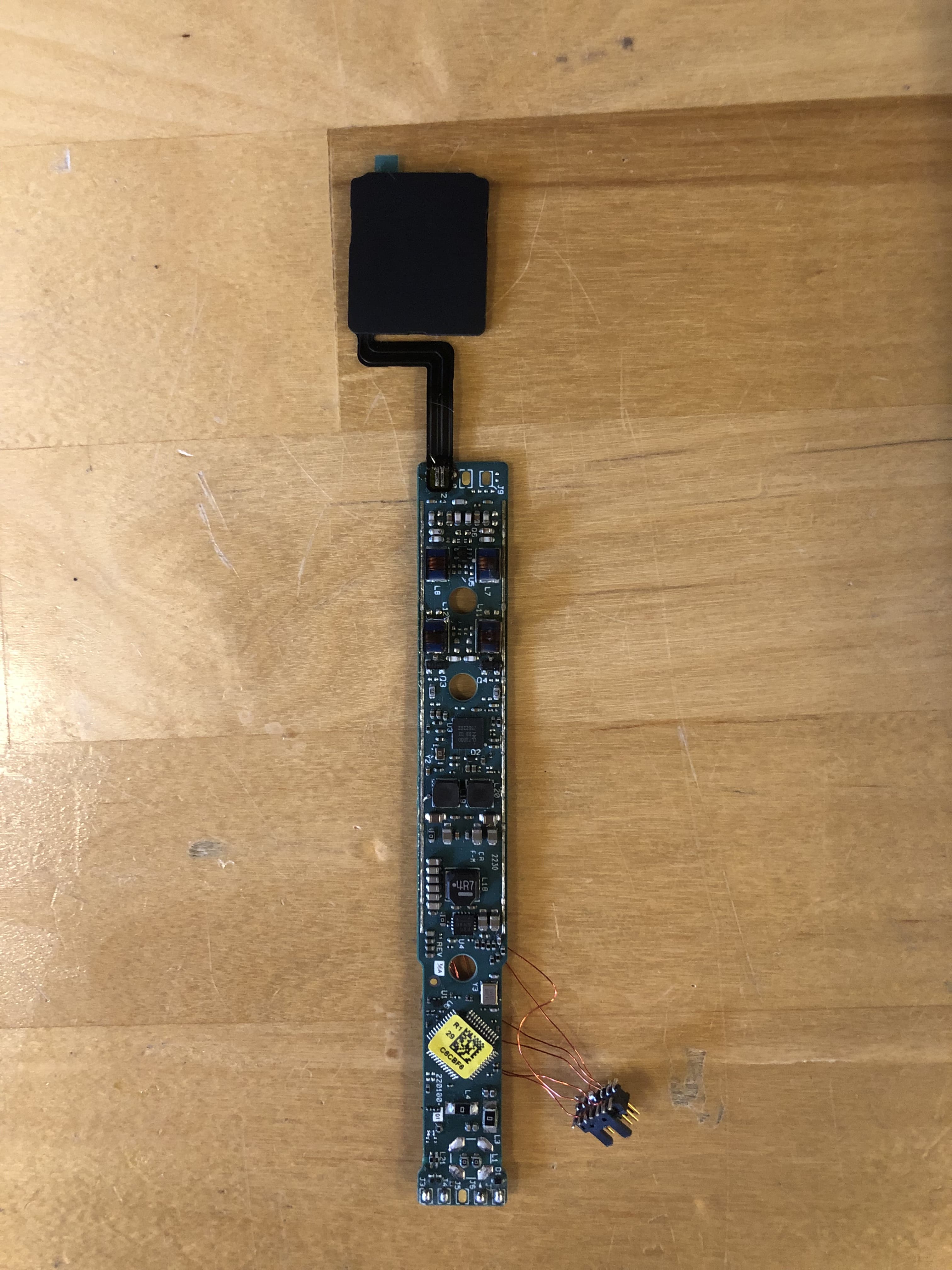
AL8-CBVS1
Oct 16, 2023Wireless Charge Stand
Equipment Class
DXX - Part 15 Low Power Communication Device Transmitter