AL8CA12CDYYYYWireless Headset Adapter - Remote Unit
HP Inc.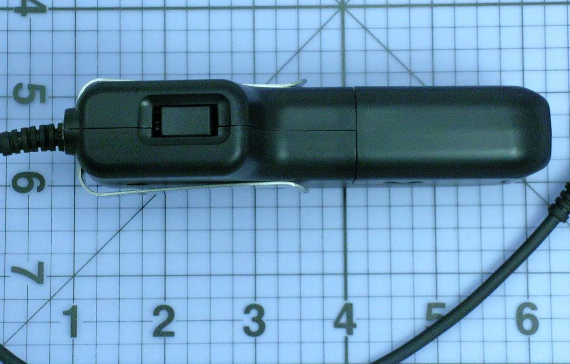
Click to zoom
Application Details
- Equipment Class
- PUT - Part 15 Unlicensed PCS portable Tx worn on body
- Date of Grant
- Oct 03, 2006
- Application Purpose
- Original Equipment
- Date of Application
- Oct 03, 2006
- Equipment Note
- Wireless Headset Adapter - Remote Unit
- Frequency Range
- 1921.53600000 - 1928.44800000
- Company
- HP Inc.
- Country
- United States
Documents & Files
Document Text
Text extracted from the exhibit documents filed with the FCC. Open a document above to read the original.
Users Manual
REMOTE CHARGE SPARE CHARGE BASE POWER TALK TALK VOLUME BASE UNITREMOTE UNIT Quick Disconnect™ for Headset Headset Volume Control (Fine Adjust) Remote On-Off Button and Indicator LED Push-to- Talk Button Selector for Momentary/ Locking PTT Function Battery Pack Battery Charging Contacts Talk (Transmit) Level Volume Control (Fine Adjust) PTT Indicator (Green) Remote Unit Battery Charging Indicator (Orange) Spare Battery Pack Charging Indicator (Orange) Base Unit Power Indicator (Green) Charging Well for Remote Unit Charging Well for Spare Battery Pack Console Interface Cable AC Adapter BOTTOM VIEW OF BASE UNIT 1.4, 2.1, 2.3, 2.4 Talk (Transmit) Level Volume Control (Course Adjust) *The factory settings provide a carbon micro- phone output level. No adjustment is typically required. Headset (Listen) Level Volume Control (Course Adjust) 1 Set-up 2 Battery Charging & Management 3 Operation Charging Well for Remote Unit Charging Well for Spare Battery Pack REMOTE CHARGE SPARE CHARGE BASE POWER TALK TALK VOLUME Talk (Transmit) Volume Control (Fine Adjust) E ER TALK VOLUME Headset (Listen) Volume Control (Fine Adjust) Push-to-Talk Headset Amplifier Note: When the Battery Pack is installed or changed, the indicator light will begin to flash as soon as the unit is ready for use. This may require up to 45 seconds as the Remote Unit determines and selects the most reliable radio channel. 1.1 Set up the CA12CD Amplifier as shown. 1.2 Plug the modular connector on the Console Interface Cable into the modular jack on the back of the Base. Plug the other end into your console. 1.3 Plug the AC Adapter into the wall outlet, and plug the round power connector into the back of the Base. The Base Power indicator will illuminate. 1.4 Slide the Battery Pack on to the Remote Unit. When the Battery Pack is installed or changed, the indicator light will begin to flash as soon as the unit is ready for use. This may require up to 45 seconds as the Remote Unit determines and selects the most reliable radio channel. 1.5 Attach a Headset to the Remote Unit. Note: Except for adjusting the Headset Volume on the Remote Unit to the users preference, no other adjustments are typically required. Please refer to Section 3 for adjustment instructions. 2.1 To attach the Battery Pack to the Remote Unit, simply slide the Battery Pack onto the Remote Unit and snap it into place. Do not force them together. 2.2 The Base Unit is equipped with 2 battery charging wells. The larger well allows charging of the battery while it is attached to the Remote Unit. The smaller well allows charging of a spare Battery Pack all by itself. 2.3 Insert the Remote Unit and the spare Battery Packs into their respective charging wells. The Charge Indicators will flash when the Battery Packs are charging. 2.4 When the Battery Pack is charged, the charge LED will stop blinking and glow steadily. 2.5 The indicator light on the Remote Unit will begin to flash as soon as the unit is ready for use. This may require up to 45 seconds as the Remote Unit determines and selects the most reliable radio channel. 2.6 A fully charged Battery Pack will usually last for an 8-hour shift. To maximize the life of the Battery Pack, turn the Remote off and place it into the charging well when not in use. Prior to being used, Battery Packs must be charged for 3 hours. Note: Swap battery packs at the end of each shift. Note: Always release/disengage PTT button before swapping Battery Packs. The CA12CD operates within the 1.92–1.93 MHz frequency range. Operation of other devices within this frequency range will reduce the user density of the CA12CD. 3.1 To maximize user density, always turn Remote Unit off when not in use. 3.2 Press the On-Off button located on top of the Remote Unit. The green On-Off indicator will begin to flash. If the battery has just been installed, the Remote Unit will automatically turn on and the On-Off indicator will begin to flash within 45 seconds. (Reference section 1.4) 3.3 Depressing the Push-To-Talk (PTT) button on the Remote Unit will generate the “key” signal to your console or radio. While the PTT button is depressed, the green Talk indicator on the Base Unit will illuminate. 3.4 The operation of the PTT button can be adjusted with a screwdriver to be either lockable or non-lockable as shown. REMOTE CHARGE SPARE CHARGE BASE POWER TALK TALK VOLUME QUICK START USER GUIDE CA12CD . . . . . . . . . . . . . . . . . . . . . . . . . . . . . . . . . . . . . . . . . . . . . . . . . . . . . . . . . . . . COMPONENTS OF THE CA12CD Plug in Console Interface Cable here Plug in AC Adapter here BACK VIEW OF BASE UNIT 1.1, 1.2, 1.3 Nonlockable Position Lockable Position 3.4 Turn the selector horizontally. The push- to-talk button can be depressed momentarily when you wish to speak. Note that the selector slot is aligned vertically. The push-to-talk button can be depressed momentarily or locked in the ON position by first depressing then sliding the button until it locks. How to select the lockable or nonlockable switch position 3.5 You should not need to adjust your Talk (transmit) level: The factory setting (coarse switch set to 4 and fine-adjust set to nominal) is perfect for most applications. If you need to change this level, first try adjusting the fine-adjust controls on the top of the Base. If you cannot get a sufficient change in output by adjusting the fine-adjust controls, change the course-adjust switch on the bottom of the Base to the next position. You may have to repeat these steps a couple of times before you get the correct Talk level. 3.6 The Listen (receive) level is set at the factory to coarse-switch position 2, and the fine-adjust rocker switch on the Remote is set to nominal. If you need to change this level, you can do so by following the steps for changing the Talk level in the previous section. 3.7 The Base and the Remote are paired with each other at the factory in a process called subscription. If you replace your Remote, or if your…
Text truncated - open the document above for the full version.
Users Manual
FCC REQUIREMENTS PART 15 This device complies with Part 15 of the FCC Rules. Operation is subject to the following two conditions: 1. This device may not cause harmful interference, and 2. This device must accept any interference received, including interference that may cause undesired operation. This equipment has been tested and found to comply with the limits for a Class B digital device, pursuant to Part 15 of the FCC Rules. These limits are designed to provide reasonable protection against harmful interference in a residential instal- lation. This equipment generates, uses, and can radiate radio frequency energy and, if not installed and used in accordance with the instructions, may cause harmful interference to radio communications. However, there is no guarantee that interference will not occur in a particular installation. If this equipment does cause harmful interference to radio or television reception which can be deter- mined by turning the radio or television off and on, the user is encouraged to try to correct interference by one or more of the following measures: 1. Reorient or relocate the receiving antenna. 2. Increase the separation between the equipment and receiver. 3. Connect the equipment into an outlet on another circuit. 4. Consult the dealer or an experienced radio/TV technician for help. Exposure to Radio Frequency Radiation This device and its antenna must not be co-located or operated in conjunction with any other antenna or transmitter. To com- ply with FCC RF exposure requirements, only use the supplied antenna. The radiated output power of this internal wireless radio is far below the FCC radio frequency exposure limits. Nevertheless, the wireless radio shall be used as described in the manual. The internal wireless radio operates within guidelines found in radio frequency safety standards and recommendations, which reflect the consensus of the scientific community. Plantronics therefore believes the internal wireless radio is safe for use by consumers. The level of energy emitted is far less than the electromagnetic energy emitted by wireless devices such as mobile phones. However, the use of wireless radios may be restricted in some situations or environments, such as aboard airplanes. If you are unsure of restrictions, you are encouraged to ask for authorization before turning on the wireless radio. NOTE: Modifications not expressly approved by Plantronics, Inc. could void the user’s authority to operate the equipment. INDUSTRY CANADA NOTICE US INDUSTRY CANADA NOTICE Radio Equipment The term “IC:” before the radio certification number only signifies that Industry Canada technical specifications were met. Operation is subject to the following two conditions: (1) this de- vice may not cause interference, and (2) this device must accept any interference, including interference that may cause unde- sired operation of the device. “Privacy of communications may not be ensured when using this telephone.” This product meets the applicable Industry Canada technical specifications of the RSS210. F AVIS INDUSTRIE CANADA Équipement radio Le terme «IC/CI» avant le numéro d’homologation radio signifi e seulement que les spécifi cations techniques d’Industrie Canada ont été respectées. Le fonctionnement de l’équipement est soumis aux deux condi- tions suivantes : (1) le dispositif ne doit créer aucune interférence nuisible, et (2) le dispositif doit accepter toute interférence reçue, y compris celles pouvant causer le fonctionnement indésirable du dispositif. « La confi dentialité des communications n’est pas assurée lors de l’usage du téléphone. » Ce produit répond aux spécifi cations techniques du ministère de l’Industrie du Canada en vigueur pour le RSS210. LIMITED WARRANTY • This warranty covers defects in materials and workmanship of products manufactured, sold or certified by Plantronics which were purchased and used in the United States. • The warranty lasts for one year from the date of purchase of the products. • This warranty extends to you only if you are the end user with the original purchase receipt. • We will at our option, repair or replace the products that do not conform to the warranty. We may use functionally equiva- lent reconditioned/refurbished/remanufactured/pre-owned or new products or parts. • To obtain service in the U.S., contact Plantronics at 800-544-4660 ext. 5538. • THIS IS PLANTRONICS’ COMPLETE WARRANTY FOR THE PRODUCTS. • This warranty gives you specific legal rights, and you may also have other rights that vary from state to state. Please contact your dealer or our service center for the full details of our limited warranty, including items not covered by this limited warranty. TECHNICAL ASSISTANCE Visit our Web site at www.plantronics.com/support for technical support including frequently asked questions, compatibility and accessibility information. The Plantronics Technical Assistance Center (TAC) is also ready to assist you on 800-544-4660 ext. 5538. www.plantronics.com 2006 Plantronics, Inc. All rights reserved Plantronics, the logo design, and Sound Innovations are trademarks or registered trademarks of Plantronics, Inc. Printed in U.S.A. 73530-01 (08.06) IMPORTANT SAFETY INSTRUCTIONS When using your telephone equipment, basic safety precautions should always be followed to reduce the risk of fire, electric shock, and injury to persons, including the following: 1. Read and understand all instructions. 2. Follow all warnings and instructions marked on the product. The symbol identifies and alerts the user to the presence of important operating and service instructions. 3. Unplug this product from the wall outlet before cleaning. Do not use liquid cleaners or aerosol cleaners. Use a damp cloth for cleaning. 4. Do not locate Base Unit near water, for example, near a bathtub or sink, in a wet basement, or near a swimming pool. 5. This product should never be placed near or over a radiator or heat register. This product should not be…
Text truncated - open the document above for the full version.
Cover Letter(s)
PCTEST Engineering Laboratory, Inc. 6660 Dobbin Road Suite A-E Columbia, Maryland 21045-4844 Tel.: 410-290-6652 / Fax: 410-290-6654 © 2006 PCTEST Engineering Lab., Inc. October 27, 2006 PCTEST TCB/CB Division of PCTEST Engineering Laboratory Inc. 6660-B Dobbin Road, Columbia, MD 21045 SUBJECT: Plantronics Inc. FCC ID: AL8CA12CDYYYY Request for Superseding Original Grant Date: October 10, 2006 Gentlemen: Transmitted herewith, on behalf of Plantronics Inc. is a request for superseding of the following exhibits for the Wireless Headset Adapter – Remote Unit 1. SAR Report 1 2. SAR Report 2 3. SAR Test Setup Photographs These exhibits have been requested for superseding because the exhibits were scanned in and the quality is not good. The new exhibits have the photographs extracted and removed from the report at a better resolution. Should you have any questions or comments concerning the above, please contact the undersigned. cc: Plantronics Inc.
External Photos
Plantronics Confidential CA12CDYYYY external photographs in support of FCC filing B.Piedra, Sep.12/2006 CA12CD Remote: Back side Removing the enclosure battery to show where the FCC ID artwork label will be placed. Battery enclosure: Front side that connects to the remote. Back side FCC ID artwork label p/n 75139 will be located on this surface of the remote unit. Plantronics Confidential Front Side Top side Lateral Side.
Internal Photos
Plantronics Confidential Internal Remote Pictures CA12CDYYYY internal photographs in support of FCC filing B. Piedra Sep. 12, 2006 From side Plantronics Confidential Back side AL8CA12CDYYYY PCBA Remote top with shield being removed AL8CA12CDYYYY PCBA Remote bottom with shield being removed
RF Exposure Info
Company: Plantronics Inc. FCC ID: AL8CA12CDYYYY 1921.536 - 1928.448 MHz Model(s): CA12CD (Remote) Device: Wireless Headset Adaptor (Remote Unit with PTT) 2006 Celltech Labs Inc. This document is not to be reproduced in whole or in part without the prior written permission of Celltech Labs Inc.Page 1 of 36 Date(s) of Evaluation September 06, 2006 Test Report Serial No. 090106AL8-T771-S15R Report Revision No. Revision 1.1 Report Issue Date October 05, 2006 Description of Test(s) Specific Absorption Rate RF Exposure Category General Population Certificate No. 2470.01 RF EXPOSURE EVALUATION SPECIFIC ABSORPTION RATE S S S A A A R R R T T T E E E S S S T T T R R R E E E P P P O O O R R R T T T FOR PLANTRONICS INC. WIRELESS HEADSET ADAPTOR (Remote Unit with PTT) MODEL: CA12CD (Remote) FCC ID: AL8CA12CDYYYY Test Report Serial No. 090106AL8-T771-S15R Test Report Revision No. Revision 1.0 (Initial Release) Revision 1.1 (Device photos removed for short-term confidentiality) Test Location Celltech Compliance Testing & Engineering Lab (Celltech Labs Inc.) 1955 Moss Court Kelowna, BC Canada V1Y 9L3 Test Report Prepared By: Cheri Frangiadakis Test Report Writer Celltech Labs Inc. Test Report Reviewed By: Jonathan Hughes General Manager Celltech Labs Inc. TEST STANDARD(S) & PROCEDURE(S) APPLIED FCC OET Bulletin 65, Supplement C (01-01) Industry Canada RSS-102 Issue 2 IEEE 1528-2003 Certificate No. 2470.01 Company: Plantronics Inc. FCC ID: AL8CA12CDYYYY 1921.536 - 1928.448 MHz Model(s): CA12CD (Remote) Device: Wireless Headset Adaptor (Remote Unit with PTT) 2006 Celltech Labs Inc. This document is not to be reproduced in whole or in part without the prior written permission of Celltech Labs Inc.Page 2 of 36 Date(s) of Evaluation September 06, 2006 Test Report Serial No. 090106AL8-T771-S15R Report Revision No. Revision 1.1 Report Issue Date October 05, 2006 Description of Test(s) Specific Absorption Rate RF Exposure Category General Population Certificate No. 2470.01 Celltech Labs Inc. declares under its sole responsibility that this wireless portable device is compliant with the Specific Absorption Rate (SAR) RF exposure requirements specified in FCC 47 CFR §2.1093 and Health Canada’s Safety Code 6. The device was tested in accordance with the measurement standards and procedures specified in FCC OET Bulletin 65, Supplement C (Edition 01-01), Industry Canada RSS-102 Issue 2 and IEEE Standard 1528-2003 for the General Population / Uncontrolled Exposure environment. All measurements were performed in accordance with the SAR system manufacturer recommendations. I attest to the accuracy of data. All measurements were performed by me or were made under my supervision and are correct to the best of my knowledge and belief. I assume full responsibility for the completeness of these measurements and vouch for the qualifications of all persons taking them. This test report shall not be reproduced partially, or in full, without the prior written approval of Celltech Labs Inc. The results and statements contained in this report pertain only to the device(s) evaluated. Test Report Approved By: Sean Johnston SAR Lab Manager Celltech Labs Inc. DECLARATION OF COMPLIANCE SAR RF EXPOSURE EVALUATION Test Lab and Location CELLTECH LABS INCORPORATED Testing and Engineering Services 1955 Moss Court Kelowna, B.C. Canada V1Y 9L3 Phone: 250-448-7047 Fax: 250-448-7046 e-mail: [email protected] web site: www.celltechlabs.com Company Information PLANTRONICS INC. 345 Encinal Street Santa Cruz, CA 95060 United States FCC ID: AL8CA12CDYYYY Model(s): CA12CD (Remote) Test Standard(s): FCC 47 CFR §2.1093; Health Canada Safety Code 6 Test Procedure(s): FCC OET Bulletin 65, Supplement C (01-01) Industry Canada RSS-102 Issue 2 IEEE 1528-2003 FCC Device Classification: Part 15 Unlicensed PCS Portable Tx worn on body (PUT) IC Device Classification: 2 GHz Licence-exempt Personal Communications Service Device (LE-PCS) Device Description: Wireless Headset Adaptor (Remote Unit with PTT) Mode(s) of Operation: TDMA/TDD Transmit Frequency Range: 1921.536 - 1928.448 MHz RF Output Power Tested: 1.7 dBm (1.48 mW) Conducted Max. Duty Cycle Tested: 8.3 % Source-Based Time-Averaged (Crest Factor: 1:12.05) Battery Type(s) Tested: Li-ion 3.8 V, 190 mAh (P/N: 65358-01) Antenna Type(s) Tested: Internal Body-Worn Accessories: Integral Metal Belt-Clip Audio Accessories Tested: Plantronics Supraplus Headset (Model: H251) Plantronics Monaural Ultra Headset (Model: H91) Plantronics Supra Monaural Headset (Model: H51/A) Max. SAR Level(s) Evaluated: Body: 0.007 W/kg (Peak SAR measured from Area Scan) Company: Plantronics Inc. FCC ID: AL8CA12CDYYYY 1921.536 - 1928.448 MHz Model(s): CA12CD (Remote) Device: Wireless Headset Adaptor (Remote Unit with PTT) 2006 Celltech Labs Inc. This document is not to be reproduced in whole or in part without the prior written permission of Celltech Labs Inc.Page 3 of 36 Date(s) of Evaluation September 06, 2006 Test Report Serial No. 090106AL8-T771-S15R Report Revision No. Revision 1.1 Report Issue Date October 05, 2006 Description of Test(s) Specific Absorption Rate RF Exposure Category General Population Certificate No. 2470.01 TABLE OF CONTENTS 1.0 INTRODUCTION___________________________________________________________________ 4 2.0 DESCRIPTION of Device Under Test (DUT)_____________________________________________ 4 3.0 SAR MEASUREMENT SYSTEM______________________________________________________ 5 4.0 MEASUREMENT SUMMARY_________________________________________________________ 6 5.0 DETAILS OF SAR EVALUATION _____________________________________________________ 7 6.0 EVALUATION PROCEDURES________________________________________________________ 7 7.0 SYSTEM PERFORMANCE CHECK____________________________________________________ 8 8.0 SIMULATED EQUIVALENT TISSUES __________________________________________________ 9 9.0 SAR SAFETY LIMITS_______________________________________________________________ 9 10.0 ROBOT SYSTEM SPECIFICATIO…
Text truncated - open the document above for the full version.
Test Report
Exhibit #11 Conducted RF and spectral etiquette measurements to support the certification of the CA12CD Base and CA12CD Remote, AL8CA12CDXXXX and AL8CA12CDYYYY. Plantronics, Ron Meck, August 23, 2006. Contents: I) Background A. EUT description 2 B. Manufacturer’s mandatory declarations 3 C. Standard test configurations 6 D. Calibration 10 E. Auxiliary Equipment 10 II) Test results summary A. Base EUT 16 B. Remote EUT 27 III) Tests of clause 6 performed by the manufacturer, for the Base EUT A. Clause 6.1 Emissions tests for the base EUT 38 B. Clause 6.2 Tests of frequency and time stability for the Base EUT 73 IV) Tests of clause 7, base EUT A. Clause 7.3.2 Upper threshold for EUTs which implement the LIC procedure, Base EUT 82 B. Clause 7.3.3 Least interfered channel (LIC) procedure test, Base EUT 84 C. Clause 7.3.4 Selected channel confirmation, Base EUT 88 D. Clause 7.5 Reaction time and monitoring interval, Base EUT 95 V) Tests of clause 8, base EUT A. Clause 8.1.1 Access criteria test interval, Base EUT 105 B. Clause 8.1.2 Access criteria functional test (47CFR15.323(c)(6) not implemented), Base EUT 110 C. Clause 8.2.1 Acknowledgements, Base EUT 113 D. Clause 8.2.2 Transmission duration, Base EUT 116 VI) Tests of clause 6 performed by the manufacturer, for the Remote EUT A. Clause 6.1 Emissions tests for the Remote EUT 117 B. Clause 6.2 Tests of frequency and time stability for the Remote EUT 151 VII) Tests of clause 7, Remote EUT A. Clause 7.3.2 Upper threshold for EUTs which implement the LIC procedure, Remote EUT 160 B. Clause 7.3.3 Least interfered channel (LIC) procedure test, Remote EUT 162 C. Clause 7.3.4 Selected channel confirmation, Remote EUT 166 D. Clause 7.5 Reaction time and monitoring interval, Remote EUT 169 VIII) Tests of clause 8, Remote EUT A. Clause 8.2.1 Acknowledgements, Remote EUT 173 B. Clause 8.2.2 Transmission duration, Remote EUT 182 1/182 I) Background I-A. EUT Description The Plantronics Model CA12CD is a cordless push-to-talk (PTT) headset adapter made to provide wireless communications and PTT functionality for dispatch operations. The system consists of a base unit that interfaces to a dispatch console communication system, and a remote unit with PTT that communicates with the base station. The remote unit has an “Ultra” style, quick disconnect connector, which attaches to a Plantronics “H” top headset that is worn by the user. The base unit provides a docking cradle for charging the remote unit and a spare battery, and is provided with an AC power adapter. Both the remote unit and the base unit are intentional radiators, designed in accordance with the requirements of 47CFR15 subpart D. The specific units tested were base unit #31 and headset #32. 2/182 I-B. Manufacturer’s Attestations, Mandatory Declarations and Descriptions The CA12CD Remote Unit and CA12CD Base Station Unit both use digital modulation. Clause 4.11 in V3.3 of (draft) C63.17-2005 requires the following declarations to be made by the manufacturer. These declarations are used in demonstrating compliance with certain sections of 47CFR15 subpart D, and in support of test parameters within V3.3 of (draft) C63.17-2005. The channel plan. Five RF carriers are used, as follows: 1928.448 MHz. 1926.720 MHz. 1924.992 MHz. 1923.264 MHz. 1921.536 MHz. Maximum EUT antenna gain GA (dBi), and orientation and polarization for maximum gain. The maximum remote EUT antenna gain is 0dBi. The antenna is elliptically polarized with the major axis of polarization normal to the top external surface of the remote disposed away from the user’s hand and/or body, and with the minor axis of polarization parallel to the length of the major axis of the remote. Two identical collocated antennas are provided for the base EUT, within the definition of V3.3 of (draft) C63.17-2005. The maximum base EUT antenna gain is 3dBi. The antennas are elliptically polarized with the major axis of polarization vertical from the top left and right corners of the base, and with the minor axis of polarization normal to the front and back surfaces of the base for left and right antennas. Maximum peak power level Maximum specified peak conducted power level for both the base and the remote EUT is +4dBm. Emission bandwidth Emission bandwidth measured according to the procedures of V3.3 (draft) C63.17-2005 clause 6.1.3 for the base EUT is 1.47MHz. Emission bandwidth measured according to the procedures of V3.3 (draft) C63.17-2005 clause 6.1.3 for the remote unit EUT is 1.49MHz. Nominal receive bandwidth Nominal receive bandwidth is +/-500kHz. 3/182 Frame period and time slot plan, if TDMA techniques are used The EUT system is a TDMA system which “further divides access in time” in the context of clause 6.2.2 of V3.3 (draft) C63.17-2005. Frame period is 10mS. There are 24 timeslots per frame, with one of the first 12 timeslots used for the remote transmissions and one of the last 12 timeslots used for the base transmissions. Transmit and receive timeslots are 5mS apart in time. Transient events occur during which two non-adjacent timeslots may be in use by the base during the setup of the communications channel, or by both the base and the remote EUT as the system does a soft handoff in response to interference. Minimum and maximum burst length, if TDMA techniques are used Minimum burst length is 90uS, the beacon transmissions from the base when a communications channel is not open. Maximum burst length is 390uS, transmissions from the remote when a communications channel is open. Minimum and maximum operating temperature range declared to the end-user The minimum operating temperature is +4C. The maximum operating temperature is +44C. Whether a system built with the EUT does or does not operate under the provisions of 47CFR15.323(c)(10) to test for deferral only in conjunction with a companion device The EUT system does not use the provisions of 47CFR15.323(c)(10) to enable testing for access criteria only in one element of the system. Bot…
Text truncated - open the document above for the full version.
Test Setup Photos
Fig. 6 - Detail of test system configured for calibration of the PXI-5670 and coupling netw ork. Power sensor connects in place of the EUT. The companion device port is terminated with an additional 20dB attenuator and 30dB attenuator in tandem. 14/182 Fig. 7 - Test bench configured for calibration of the PXI-5670 and coupling network; general view. 15/182 VI) Tests of clause 6, CA12CD Remote EUT VI-A. Clause 6.1 Emissions tests for the headset EUT For the tests of clause 6.1 of V3.3 (draft) C63.17-2005, the test platform and remote EUT are configured according to test configuration #2, Conducted emissions tests, headset EUT, of section (I) of this document. The remote EUT is established in a communications channel with the base companion device by means of a radiative-coupled connection, though the remote EUT is in conducted connection to the spectrum analyzer, per figure 3 of v3.3 (draft) C63.17-2005 in clause 6.1.1. Administrative commands are used to set the base to the desired carrier for the test, and so the remote EUT is constrained to use those carriers, since it uses the carriers that the base is constrained to. Fig. 78 - Remote EUT in direct connection with spectrum analyzer and radiated connection with base companion device, for the tests of clause 6.1. 117/182 Fig. 79 – Remote EUT- Detail of the attachment of the RF connection for conducted measurements. 118/182 Fig. 110 - View of test system configured for the tests of clau se 6.2.1 for the headset EUT. EU T is in the temperature chamber at right. EUT power supply is top right. EUT RF cabling is connected as described in the te xt, to the CMD60 analyzer and the E4407B spectrum analyzer. The controller interface circuit (RS232 to CMOS levels) is directlyoutside the chamber egress. 152/182 Fig. 111 - Remote EUT within the temperatu re chamber, with RF connection to EUT and with power/control ca ble connection to EUT. 153/182 Fig. 112 - Detail of remote EUT as tested within th e temperature chamber for the tests of clause 6.2. 154/182
Test Setup Photos
Company: Plantronics Inc. FCC ID: AL8CA12CDYYYY 1921.536 - 1928.448 MHz Model(s): CA12CD (Remote) Device: Wireless Headset Adaptor (Remote Unit with PTT) 2006 Celltech Labs Inc. This document is not to be reproduced in whole or in part without the prior written permission of Celltech Labs Inc. Page 27 of 36 Date(s) of Evaluation September 06, 2006 Test Report Serial No. 090106AL8-T771-S15R Report Revision No. Revision 1.1 Report Issue Date October 05, 2006 Description of Test(s) Specific Absorption Rate RF Exposure Category General Population Certificate No. 2470.01 APPENDIX D - SAR TEST SETUP & DUT PHOTOGRAPHS Company: Plantronics Inc. FCC ID: AL8CA12CDYYYY 1921.536 - 1928.448 MHz Model(s): CA12CD (Remote) Device: Wireless Headset Adaptor (Remote Unit with PTT) 2006 Celltech Labs Inc. This document is not to be reproduced in whole or in part without the prior written permission of Celltech Labs Inc. Page 28 of 36 Date(s) of Evaluation September 06, 2006 Test Report Serial No. 090106AL8-T771-S15R Report Revision No. Revision 1.1 Report Issue Date October 05, 2006 Description of Test(s) Specific Absorption Rate RF Exposure Category General Population Certificate No. 2470.01 3 mm BODY SAR TEST SETUP PHOTOGRAPHS Left Belt-Clip Side of DUT Touching SAM Phantom (Planar Section) (3 mm Belt-Clip Spacing from Left Side of DUT to Phantom) Company: Plantronics Inc. FCC ID: AL8CA12CDYYYY 1921.536 - 1928.448 MHz Model(s): CA12CD (Remote) Device: Wireless Headset Adaptor (Remote Unit with PTT) 2006 Celltech Labs Inc. This document is not to be reproduced in whole or in part without the prior written permission of Celltech Labs Inc. Page 29 of 36 Date(s) of Evaluation September 06, 2006 Test Report Serial No. 090106AL8-T771-S15R Report Revision No. Revision 1.1 Report Issue Date October 05, 2006 Description of Test(s) Specific Absorption Rate RF Exposure Category General Population Certificate No. 2470.01 BODY SAR TEST SETUP PHOTOGRAPHS Right Belt-Clip Side of DUT Touching SAM Phantom (Planar Section) (3 mm Belt-Clip Spacing from Right Side of DUT to Phantom) 3 mm Company: Plantronics Inc. FCC ID: AL8CA12CDYYYY 1921.536 - 1928.448 MHz Model(s): CA12CD (Remote) Device: Wireless Headset Adaptor (Remote Unit with PTT) 2006 Celltech Labs Inc. This document is not to be reproduc…
Text truncated - open the document above for the full version.
Contact Information
Applicant
Richard Tarsio(US/CAN TRSE Worldwide Technical Regulations)
Technical Contact
PCTEST Engineering Laboratory, Inc.Randy Ortanez
[email protected]410-290-6652
6660-B Dobbin Road · Columbia, Maryland · United States
Test Firm
Element Materials Technology Fremont NewarkDavid Bare
Technical Specifications
| # | Rule Parts | Frequency Range | Power Output |
|---|---|---|---|
| 1 | 15D | 1.92 GHz - 1.93 GHz | 1.20 mW |
Other Applications from HP Inc.
AL8-PWPTF620P
Feb 03, 2026Wireless Charge Stand
Equipment Class
DCD - Part 15 Low Power Transmitter Below 1705 kHzAL8-PBF620F
Jan 23, 2026Bluetooth Headset
Equipment Class
DTS - Digital Transmission SystemAL8-PBVOYX2
Jun 20, 2024Bluetooth Base
Equipment Class
DTS - Digital Transmission System
AL8-VF2R
Mar 07, 2024Wireless Bluetooth Earphones
Equipment Class
DTS - Digital Transmission System
AL8-CBVS1
Oct 16, 2023Wireless Charge Stand
Equipment Class
DXX - Part 15 Low Power Communication Device Transmitter