AL8CS3YYYYWireless Telephone Adapter Headset
HP Inc.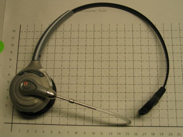
Click to zoom
Application Details
- Equipment Class
- PUE - Part 15 Unlicensed PCS portable Tx held to ear
- Date of Grant
- Jan 10, 2006
- Application Purpose
- Original Equipment
- Date of Application
- Jan 10, 2006
- Equipment Note
- Wireless Telephone Adapter Headset
- Frequency Range
- 1921.53600000 - 1928.44800000
- Company
- HP Inc.
- Country
- United States
Documents & Files
Document Text
Text extracted from the exhibit documents filed with the FCC. Open a document above to read the original.
Users Manual
SOUND INNOVATION USER GUIDE_ SupraPlus ® Wireless ...................................................................................... PROFESSIONAL HEADSET SYSTEM ©2005 Plantronics, Inc. All rights reserved. Plantronics, the logo design, IntelliStand, Plantronics Sound Innovation, SupraPlus, and the voice tube clear color and shape trade dress are trademarks or registered trademarks of Plantronics, Inc. All other trademarks are the property of their respective owners. Patents U.S. 6,735,453; Patents Pending Printed in China. 71677-01 (11.05) WARRANTY Limited Warranty • This warranty covers defects in materials and workmanship of products manufactured, sold or certified by Plantronics which were purchased and used in the United States. • This warranty lasts for one year from the date of purchase of the products. • This warranty extends to you only if you are the end user with the original purchase receipt. • We will, at our option, repair or replace the products that do not conform to the warranty. We may use functionally equivalent reconditioned/refurbished/ remanufactured/pre-owned or new products or parts. • To obtain service in the U.S., contact Plantronics at (800) 544-4660 ext. 5538. • THIS IS PLANTRONICS’ COMPLETE WARRANTY FOR THE PRODUCTS. • This warranty gives you specific legal rights, and you may also have other rights that vary from state to state. Please contact your dealer or our service center for the full details of our limited warranty, including items not covered by this limited warranty. The Plantronics Technical Assistance Center is ready to assist you! Dial (800) 544-4660 ext. 5538, or visit the support section of our website at www.plantronics.com/support. TECHNICAL ASSISTANCE MAINTENANCE 1. Unplug the unit from the telephone and the AC charger from the power source before cleaning. 2. Clean the equipment with a damp (not wet) cloth. 3. Do not use solvents or other cleaning agents. 3 2 PACKAGE CONTENTS Telephone Cord Base Headset ( Onemodel included in eachpackage—allavailablemodels shown.) AC Charger Handset Lifter (Optional) Handset Lifter Monaural Voice Tube Monaural Noise-canceling Binaural Noise-canceling Binaural Voice Tube Ringer Microphone Extender Arm withStabilizers For Norteli2004 phonesonly Additional parts (if required). Detailson page22. Alternative Ear Cushions Removable Comfort Pad TABLE OF CONTENTS Package Contents Features Setup Positioning Adjusting Fit Charging CheckingCompatibility 3 4 6 9 9 8 11 Making/Answering/Ending Calls 10 Multi-shift Pairing 10 Headset Controls Volume 16 Setup – Handset Lifter (Optional) 14 13 Troubleshooting 18 Base Indicator Lights 17 Battery Replacement 21 Subscription 20 20 System Reset 22 Additional Parts (if required) Regulatory Notices 23 Visit www.plantronics.com/productregistrationto register your product online so we can provide you with the best possible service and technical support. Register Your Product Online 5 4 FEATURESFEATURES Listening Volume Mute Talk Indicator Light Call Control Button Voice Tube or Noise-Canceling Microphone Lifter Arm Ringer Microphone Jack (remove cover) Height Switch Accessory Jack Power Cord Headset Handset Lifter Charging Cradle Front: Indicator Lights Talk (Green) Power (Red) Charge (Amber) Telephone Configuration Dial Rear: Listening Volume Major Adjust Telephone Cord IntelliStand On/Off Switch (to automate call control button) Speaking Volume Minor Adjust Base - Top View Base - Bottom View Telephone Cord Jack Telephone Handset Jack Speaking Volume Major Adjust AC Charging Jack Lifter Jack Listening Volume Mute Talk Indicator Light Call Control Button Voice Tube or Noise-Canceling Microphone Lifter Arm Ringer Microphone Jack (remove cover) Height Switch Accessory Jack Power Cord Headset Handset Lifter Charging Cradle Front: Indicator Lights Talk (Green) Power (Red) Charge (Amber) Telephone Configuration Dial Rear: Listening Volume Major Adjust Telephone Cord IntelliStand On/Off Switch (to automate call control button) Speaking Volume Minor Adjust Base - Top View Base - Bottom View Telephone Cord Jack Telephone Handset Jack Speaking Volume Major Adjust AC Charging Jack Lifter Jack 7 6 3A 4A Base - Bottom View Complete ! 9 v A D B C SETUP Plug the AC charger into the base’s AC charging jack. Push in firmly. Plug the handset cord into the handset jack in the base. Push in until it clicks. 2 SETUP 1 Unplug the handset cord from phone.Plug the phone cord that is connected to the SupraPlus base into the handset jack on the phone. CAUTION: Your phone may have two similar jacks. Put the cord only in the jack from which the handset came. Plug the AC charger into an outlet and into the base’s AC charging jack. See step 4 4 A A for detailed location. 4 3 Plug the handset cord into the handset jack in the bottom of the base. See step 3 3 A A for detailed location. NOTE: The access to the handset jack is fairly small. If you have large hands you may want to ask someone with smaller fingers to do this step. 9 8 6 “ 1 2 ” The m m i i n n i i m m u u m m recommended separation distance is shown above. IMPORTANT:Incorrect positioning can cause noise and interference problems. CHARGING 2 1 POSITIONING 1. Slide headset into charging cradle; the earpiece with the microphone goes into the cradle. 2. Gently press down on the headset to ensure that headset is in correct position. Amber charge indicator light on base will flash while charging and will change to solid amber when fully charged. • 20 minutes = minimum charge to continue setup • 3 hours = full charge SETUP — HANDSET LIFTER (OPTIONAL) 3 IntelliStand off IntelliStand on Set the IntelliStand switch to IntelliStand off ( –) if you want to control the handset lifter with the call control button on your headset. Set the IntelliStand switch to IntelliStand on ( =) if you want the handset to automatically pick up when you take the headset off the charging cradle. 21 1. Plug handset lifter power cord into handset lifter jack on base. Push firmly…
Text truncated - open the document above for the full version.
Attestation Statements
Attn: Reviewing Engineer Federal Communications Commission 7435 Oakland Mills Road Columbia, MD 21046 December 7, 2005 RE: Confidentiality Request for AL8CS3YYYY headset To Whom It May Concern: This letter serves as an official request for confidentiality under FCC Rule Section 0.459. We request that: 1) Exhibit 6a, 6b the schematic diagrams 2) Exhibit 5 the detailed block diagram 3) Exhibit 4 the detailed theory of operation required to be submitted with this application be withheld from public review. These documents are company proprietary information that is not publicly available, and would damage Plantronics’ commercial interests if made public. Please contact me if there is any information that you may need. Regards Wilmer Lau RF Engineer Plantronics [email protected]
External Photos
Plantronics Confidential Supra Plus Wireless Pictures AL8CS3YYYY external photographs in support of FCC filing W. Lau, Dec. 7/2005 Monaural Voice Tube CS351: Laser marking area to place the FCC ID # and Model. Note: The laser marking will be at the same area for all of the headsets variants. Plantronics Confidential Monaural Noise Cancelling CS351N: Laser marking area to place the FCC ID # and Model Plantronics Confidential Binaural Voice Tube CS361: Laser marking area to place the FCC ID # and Model Plantronics Confidential Binaural Noise Cancelling CS61N: Laser marking area to place the FCC ID # and Model
ID Label/Location Info
72526-00 68881-01 XX see part dwg. © 2005 ARTMASTER #: REV. LEVEL: REF. PART #: DESCRIPTION: PREPARED BY:DATE: PMS COLOR #: Laser Marking Artwork-SupraPlus Wireless Headset G W Skulley13dec05 ec ner e fer 1: 1 1 :1 : elac S 1 : 4 : e l a cS t p 4 . 5 w o r r aN l ai rA t p 4 . 5 w o r r aN l ai rA t p 4. 5 l a irA s cinortnal P CS XXXX CS3YYYY8L A :D I CCF Made in China s cinortnal P CS XXXX CS3YYYY8L A :D I CCF Made in China s cinortnal P CS XXXX CS3YYYY8L A :D I CCF Made in China t p 4 . 5 l a irA s cinortnal P CS XXXX CS3YYYY8L A :D I CCF Made in China -01 SupraPlus Wireless Monaural VT: = Plantronics CS 351 -02 SupraPlus Wireless Binaural VT: = Plantronics CS 361 -03 SupraPlus Wireless Monaural NC: = Plantronics CS 351N -04 SupraPlus Wireless Binaural NC: = Plantronics CS 361N US CS Model #s Plantronics CS 3xxxx Speaker Capsule Back view
Internal Photos
Plantronics Confidential Supra Plus Wireless Internal Pictures AL8CS3YYYY internal photographs in support of FCC filing W. Lau, Dec 7, 2005 AL8CS3YYYY side A with detached shield Plantronics Confidential AL8CS3YYYY side B with detached shield
RF Exposure Info
Applicant: Plantronics Inc. DUT Type: Wireless Professional Headset System (UPCS) Product: SupraPlus Wireless Models: CS351, CS361, CS351N, CS361N 1921.536 - 1928.448 MHz 2005 Celltech Labs Inc. This document is not to be reproduced in whole or in part without the prior written permission of Celltech Labs Inc. Page 1 of 52 Test Report Serial No.: 102705AL8-T685-S15T Report Issue Date: January 05, 2006 Date(s) of Evaluation: November 01, 2005 Report Issue No.: S685T-010506-R2 Description of Test(s): RF Exposure SAR FCC §2.1093 IC RSS-102 Issue 2 Test Report Prepared By: Cheri Frangiadakis Test Report Writer Celltech Labs Inc. Test Report Approved By: Jonathan Hughes General Manager Celltech Labs Inc. RF EXPOSURE EVALUATION SPECIFIC ABSORPTION RATE SAR TEST REPORT FOR PLANTRONICS INC. WIRELESS HEADSET SYSTEM (UPCS) PRODUCT NAME: SUPRAPLUS WIRELESS Test Report Serial Number 102705AL8-T685-S15T Test Report Issue No. S685T-010506-R2 Test Lab Celltech Compliance Testing & Engineering Lab (Celltech Labs Inc.) 1955 Moss Court Kelowna, BC Canada V1Y 9L3 MODEL(S) DESCRIPTION CS351 Monaural Voice Tube CS351N Monaural Noise-canceling CS361 Binaural Voice Tube CS361N Binaural Noise-Canceling Applicant: Plantronics Inc. DUT Type: Wireless Professional Headset System (UPCS) Product: SupraPlus Wireless Models: CS351, CS361, CS351N, CS361N 1921.536 - 1928.448 MHz 2005 Celltech Labs Inc. This document is not to be reproduced in whole or in part without the prior written permission of Celltech Labs Inc. Page 2 of 52 Test Report Serial No.: 102705AL8-T685-S15T Report Issue Date: January 05, 2006 Date(s) of Evaluation: November 01, 2005 Report Issue No.: S685T-010506-R2 Description of Test(s): RF Exposure SARFCC §2.1093 IC RSS-102 Issue 2 DECLARATION OF COMPLIANCE SAR RF EXPOSURE EVALUATION Test Lab CELLTECH LABS INC. Testing and Engineering Services 1955 Moss Court Kelowna, B.C. Canada V1Y 9L3 Phone: 250-448-7047 Fax: 250-448-7046 e-mail: [email protected] web site: www.celltechlabs.com Applicant Information PLANTRONICS INC. 345 Encinal Street Santa Cruz, CA 95060 United States Product Name: SupraPlus Wireless Model(s): CS351 (Monaural Voice Tube) CS351N (Monaural Noise Canceling) CS361 (Binaural Voice Tube) CS361N (Binaural Noise Canceling) Rule Part(s): FCC 47 CFR §2.1093; IC RSS-102 Issue 1 (Provisional) Test Procedure(s): FCC OET Bulletin 65, Supplement C (01-01) Device Classification: Part 15 Unlicensed PCS portable Tx held to ear (PUE) Device Description: Wireless Professional Headset System (UPCS) Mode of Operation: TDMA (Time Division Multiple Access) Tx Frequency Range(s): 1921.536 - 1928.448 MHz RF Output Power Tested: 7.9 dBm (6.2 mW) Peak Conducted (CS351) 7.9 dBm (6.2 mW) Peak Conducted (CS361) 8.1 dBm (5.4 mW) Peak Conducted (CS351N) 7.9 dBm (6.2 mW) Peak Conducted (CS361N) Max. Duty Cycle Tested: 8.3% Source-Based Time-Averaged (Crest Factor: 1:12.05) Antenna Type(s) Tested: Internal Printed F Battery Type(s) Tested: Lithium-ion 4.2 V Max. SAR Level(s) Evaluated: Head: 0.013 W/kg (Peak SAR measured from Area Scan) Celltech Labs Inc. declares under its sole responsibility that this wireless portable device is compliant with the Specific Absorption Rate (SAR) RF exposure requirements specified in FCC 47 CFR §2.1093 and Health Canada’s Safety Code 6. The device was tested in accordance with the measurement standards and procedures specified in FCC OET Bulletin 65, Supplement C (Edition 01-01), Industry Canada RSS-102 Issue 1 (Provisional) and IEEE Standard 1528-2003 for the General Population / Uncontrolled Exposure environment. All measurements were performed in accordance with the SAR system manufacturer recommendations. I attest to the accuracy of data. All measurements were performed by me or were made under my supervision and are correct to the best of my knowledge and belief. I assume full responsibility for the completeness of these measurements and vouch for the qualifications of all persons taking them. This test report shall not be reproduced partially, or in full, without the prior written approval of Celltech Labs Inc. The results and statements contained in this report pertain only to the device(s) evaluated. Tested By: Sean Johnston Compliance Technologist Celltech Labs Inc. Reviewed By: Spencer Watson Senior Compliance Technologist Celltech Labs Inc. Applicant: Plantronics Inc. DUT Type: Wireless Professional Headset System (UPCS) Product: SupraPlus Wireless Models: CS351, CS361, CS351N, CS361N 1921.536 - 1928.448 MHz 2005 Celltech Labs Inc. This document is not to be reproduced in whole or in part without the prior written permission of Celltech Labs Inc. Page 3 of 52 Test Report Serial No.: 102705AL8-T685-S15T Report Issue Date: January 05, 2006 Date(s) of Evaluation: November 01, 2005 Report Issue No.: S685T-010506-R2 Description of Test(s): RF Exposure SARFCC §2.1093 IC RSS-102 Issue 2 TABLE OF CONTENTS 1.0 INTRODUCTION___________________________________________________________________ 4 2.0 DESCRIPTION OF DEVICE UNDER TEST (DUT) _________________________________________ 4 3.0 SAR MEASUREMENT SYSTEM _______________________________________________________ 5 4.0 MEASUREMENT SUMMARY _________________________________________________________ 6 5.0 DETAILS OF SAR EVALUATION ______________________________________________________ 7 6.0 EVALUATION PROCEDURES ________________________________________________________ 8 7.0 SYSTEM PERFORMANCE CHECK ___________________________________________________ 10 8.0 SIMULATED EQUIVALENT TISSUES _________________________________________________ 11 9.0 SAR SAFETY LIMITS ______________________________________________________________ 11 10.0 ROBOT SYSTEM SPECIFICATIONS _________________________________________________ 12 11.0 PROBE SPECIFICATION (ET3DV6) __________________________________________________ 13 12.0 SAM PHANTOM V4.0C ____________________________________________________________ 13 13.0 DEVICE HOLDER ______________________________________…
Text truncated - open the document above for the full version.
RF Exposure Info
Applicant: Plantronics Inc. DUT Type: Wireless Professional Headset System (UPCS) Product: SupraPlus Wireless Models: CS351, CS361, CS351N, CS361N 1921.536 - 1928.448 MHz 2005 Celltech Labs Inc. This document is not to be reproduced in whole or in part without the prior written permission of Celltech Labs Inc. Page 51 of 52 Test Report Serial No.: 102705AL8-T685-S15T Report Issue Date: January 05, 2006 Date(s) of Evaluation: November 01, 2005 Report Issue No.: S685T-010506-R2 Description of Test(s): RF Exposure SARFCC §2.1093 IC RSS-102 Issue 2 APPENDIX F - PROBE CALIBRATION
RF Exposure Info
Applicant: Plantronics Inc. DUT Type: Wireless Professional Headset System (UPCS) Product: SupraPlus Wireless Models: CS351, CS361, CS351N, CS361N 1921.536 - 1928.448 MHz 2005 Celltech Labs Inc. This document is not to be reproduced in whole or in part without the prior written permission of Celltech Labs Inc. Page 50 of 52 Test Report Serial No.: 102705AL8-T685-S15T Report Issue Date: January 05, 2006 Date(s) of Evaluation: November 01, 2005 Report Issue No.: S685T-010506-R2 Description of Test(s): RF Exposure SARFCC §2.1093 IC RSS-102 Issue 2 APPENDIX E - SYSTEM VALIDATION 1900 MHz System Validation Dipole (Brain) Celltech Labs Inc. 1955 Moss Court, Kelowna, B.C. Canada V1Y 9L3 Tel. 250-448-7047 x Fax. 250-448-7046 x e-mail: [email protected] www.celltechlabs.com 1900 MHz SYSTEM VALIDATION DIPOLE Type: Asset Number: Serial Number: Place of Calibration: Date of Calibration: Celltech Labs Inc. hereby certifies that this device has been calibrated on the date indicated above. Calibrated by: Approved by: 1900 MHz Validation Dipole 151 June 17, 2005 00032 Celltech Labs Inc. 1900 MHz System Validation Dipole (Brain) 2005 Celltech Labs Inc. 2 of 12 1. Dipole Construction & Electrical Characteristics The validation dipole was constructed in accordance with the IEEE Standard “Annex G (informative) Reference dipoles for use in system validation”. The electrical properties were measured using an HP 8753ET Network Analyzer. The network analyzer was calibrated to the validation dipole N-type connector feed point using an HP85032E Type N calibration kit. The dipole was placed parallel to a planar phantom at a separation distance of 10.0mm from the simulating fluid using a loss-less dielectric spacer. The measured input impedance is: Feed point impedance at 1900MHz Re{Z} = 47.803: Im{Z} = 6.4002: Return Loss at 1900MHz -23.205dB 1900 MHz System Validation Dipole (Brain) 2005 Celltech Labs Inc. 3 of 12 2. Validation Dipole VSWR Data 1900 MHz System Validation Dipole (Brain) 2005 Celltech Labs Inc. 4 of 12 3. Validation Dipole Dimensions Frequency (MHz) L (mm) h (mm) d (mm) 300 420.0 250.0 6.2 450 288.0 167.0 6.2 835 161.0 89.8 3.6 900 149.0 83.3 3.6 1450 89.1 51.7 3.6 1800 72.0 41.7 3.6 1900 68.0 39.5 3.6 2000 64.5 37.5 3.6 2450 51.8 30.6 3.6 3000 41.5 25.0 3.6 4. Validation Phantom The validation phantom is the SAM (Specific Anthropomorphic Mannequin) phantom manufactured by Schmid & Partner Engineering AG. The SAM phantom is a Fiberglass shell integrated in a wooden table. The shape of the shell corresponds to the phantom defined by SCC34-SC2. It enables the dosimetric evaluation of left and right hand phone usage as well as body mounted usage at the flat phantom region. A cover prevents evaporation of the liquid. Reference markings on the phantom allow the complete setup of all predefined phantom positions and measurement grids by manually teaching three points in the robot. Shell Thickness: 2.0 ± 0.1 mm Filling Volume: Approx. 25 liters Dimensions: 50 cm (W) x 100 cm (L) 1900 MHz System Validation Dipole (Brain) 2005 Celltech Labs Inc. 5 of 12 5. 1900 MHz System Validation Setup 1900 MHz System Validation Dipole (Brain) 2005 Celltech Labs Inc. 6 of 12 1900 MHz System Validation Setup 1900 MHz System Validation Dipole (Brain) 2005 Celltech Labs Inc. 7 of 12 6. Measurement Conditions The SAM phantom was filled with 1900 MHz brain simulating tissue. Relative Permittivity: 38.4 Conductivity: 1.40 mho/m Ambient Temperature: 23.4 qC Fluid Temperature: 22.7 qC Fluid Depth: t 15.0 cm Barometric Pressure: 100.6 kPa Humidity: 35% The 1900 MHz tissue simulant consists of the following ingredients: IngredientPercentage by weight Water 55.85% Glycol 44.00% Salt 0.15% Target Dielectric Parameters at 22 qC H r = 40.0 V = 1.40 S/m 1900 MHz System Validation Dipole (Brain) 2005 Celltech Labs Inc. 8 of 12 7. SAR Measurement The SAR measurement was performed with the E-field probe in mechanical detection mode only. The setup and determination of the forward power into the dipole was performed using the following procedures. PM1 Att1 x Dipole 3D Probe positioner Flat Phantom Field probe Signal Generator AmpLow Pass 3dB Att3 Dir.Coupler Att2 PM2 Cable PM3 d First the power meter PM1 (including attenuator Att1) is connected to the cable to measure the forward power at the location of the dipole connector (X). The signal generator is adjusted for the desired forward power at the dipole connector (taking into account the attenuation of Att1) as read by power meter PM2. After connecting the cable to the dipole, the signal generator is readjusted for the same reading at power meter PM2. If the signal generator does not allow adjustment in 0.01dB steps, the remaining difference at PM2 must be taken into consideration. PM3 records the reflected power from the dipole to ensure that the value is not changed from the previous value. The reflected power should be 50dB below the forward power. 1900 MHz System Validation Dipole (Brain) 2005 Celltech Labs Inc. 9 of 12 8. Validation Dipole SAR Test Results Ten SAR measurements were performed in order to achieve repeatability and to establish an average target value. Validation Measurement SAR @ 0.25W Input averaged over 1g SAR @ 1W Input averaged over 1g SAR @ 0.25W Input averaged over 10g SAR @ 1W Input averaged over 10g Peak SAR @ 0.25W Input Test 1 9.97 39.88 5.20 20.80 17.7 Test 2 10.0 40.00 5.19 20.76 17.9 Test 3 10.1 40.40 5.21 20.84 18.1 Test 4 9.98 39.92 5.20 20.80 17.8 Test 5 9.96 39.84 5.19 20.76 17.7 Test 6 9.99 39.96 5.18 20.72 17.9 Test 7 9.89 39.56 5.16 20.64 17.5 Test 8 9.95 39.80 5.19 20.76 17.6 Test 9 9.96 39.84 5.20 20.80 17.6 Test 10 9.92 39.68 5.19 20.76 17.5 Average 9.972 39.888 5.191 20.764 17.73 The results have been normalized to 1W (forward power) into the dipole. 1g/10g Averaged Average Measured SAR @ 1W Input IEEE Target SAR @ 1W Input Deviation (%) 1 gram 39.888 39.7 + 0.474 10 gram 20.764 20.5 + 1.29 1900 MHz System Validation Dipole (Brain) 2005 Cel…
Text truncated - open the document above for the full version.
Test Report
File: R61958 November 22, 2005 Blanca Piedra Plantronics 345 Encinal Street Santa Cruz, CA 95061-0635 Subject: FCC Emissions Report, CS351N Monaural Noise Cancelling Headset and Base (CS351N Mon NC); CS361N Binaural Noise Cancelling Headset and Base (CS361N Bin NC) Dear Ms. Piedra: A report has been created detailing the results of the FCC electromagnetic emissions testing performed on the CS351N Monaural Noise Cancelling Headset and Base (CS351N Mon NC); CS361N Binaural Noise Cancelling Headset and Base (CS361N Bin NC). Please find this report enclosed. Per Federal Communication Commission regulations, the signature of an official of the company responsible for marketing the CS351N Monaural Noise Cancelling Headset and Base (CS351N Mon NC); CS361N Binaural Noise Cancelling Headset and Base (CS361N Bin NC) is required, for this report, to be acceptable for determining compliance. We recommend filing this report in a safe place for future reference. Once an official has signed page 4 of this report, you may begin shipping the CS351N Monaural Noise Cancelling Headset and Base (CS351N Mon NC); CS361N Binaural Noise Cancelling Headset and Base (CS361N Bin NC). Each unit must be manufactured with any modifications described in the report, the proper FCC label should be attached and the appropriate FCC statement should be included in the operator's manual. If you have any questions, please don't hesitate to call us at 408-245-7800. Sincerely, Mark Briggs Principal Engineer MB/dmg Enclosure: Emissions Report File: R61958 Page 1 of 16 Electromagnetic Emissions Test Report for Verification of Compliance per FCC Part 15, Subpart B Specifications for a Class B Digital Device and ICES-003 Class B and Subpart D – Unlicensed Personal Communications Devices on the Plantronics Model: CS351N Monaural Noise Cancelling Headset and Base (CS351N Mon NC); CS361N Binaural Noise Cancelling Headset and Base (CS361N Bin NC) MANUFACTURER: Plantronics 345 Encinal Street Santa Cruz, CA 95061-0635 TEST SITE: Elliott Laboratories, Inc. 41039 Boyce Road Fremont, CA. 94538-2435 REPORT DATE: November 22, 2005 FINAL TEST DATES: November 8 and November 11, 2005 AUTHORIZED SIGNATORY: ______________________________ Mark Briggs Principal Engineer Elliott Laboratories, Inc. is accredited by the A2LA, certificate number 2016-01, to perform the test(s) listed in this report. This report shall not be reproduced, except in its entirety, without the written approval of Elliott Laboratories, Inc. 2016-01 Elliott Laboratories, Inc. -- EMC Department Test Report Report Date: November 22, 2005 File: R61958 Page 2 of 16 pages TABLE OF CONTENTS COVER PAGE...................................................................................................................................................................................1 TABLE OF CONTENTS..............................................................................................................................................................2 SCOPE............................................................................................................................................................................................3 VALIDATING SIGNATURES.....................................................................................................................................................4 OBJECTIVE...................................................................................................................................................................................4 EMISSION TEST RESULTS.......................................................................................................................................................5 LIMITS OF CONDUCTED INTERFERENCE VOLTAGE.....................................................................................................5 LIMITS OF RADIATED INTERFERENCE FIELD STRENGTH..........................................................................................5 MEASUREMENT UNCERTAINTIES....................................................................................................................................6 EQUIPMENT UNDER TEST (EUT) DETAILS..........................................................................................................................7 GENERAL...................................................................................................................................................................................7 OTHER EUT DETAILS.............................................................................................................................................................8 ENCLOSURE..............................................................................................................................................................................8 MODIFICATIONS.....................................................................................................................................................................8 SUPPORT EQUIPMENT...........................................................................................................................................................9 EUT INTERFACE PORTS........................................................................................................................................................9 EUT OPERATION.....................................................................................................................................................................9 TEST SITE....................................................................................................................................................................................10 GENERAL INFORMATION...................................................................................................................................................10 CONDUCTED EMISSIONS CONSIDERATIONS..........…
Text truncated - open the document above for the full version.
Test Report
File: R61957 November 22, 2005 Blanca Piedra Plantronics 345 Encinal Street Santa Cruz, CA 95061-0635 Subject: FCC Emissions Report, CS351 Monaural Voice Tube Headset and Base (CS351 Mon VT); CS361 Binaural Voice Tube Headset and Base (CS361 Bin VT) Dear Ms. Piedra: A report has been created detailing the results of the FCC electromagnetic emissions testing performed on the CS351 Monaural Voice Tube Headset and Base (CS351 Mon VT); CS361 Binaural Voice Tube Headset and Base (CS361 Bin VT). Please find this report enclosed. Per Federal Communication Commission regulations, the signature of an official of the company responsible for marketing the CS351 Monaural Voice Tube Headset and Base (CS351 Mon VT); CS361 Binaural Voice Tube Headset and Base (CS361 Bin VT) is required, for this report, to be acceptable for determining compliance. We recommend filing this report in a safe place for future reference. Once an official has signed page 4 of this report, you may begin shipping the CS351 Monaural Voice Tube Headset and Base (CS351 Mon VT); CS361 Binaural Voice Tube Headset and Base (CS361 Bin VT). Each unit must be manufactured with any modifications described in the report, the proper FCC label should be attached and the appropriate FCC statement should be included in the operator's manual. If you have any questions, please don't hesitate to call us at 408-245-7800. Sincerely, Mark Briggs Principal Engineer MB/dmg Enclosure: Emissions Report File: R61957 Page 1 of 16 Electromagnetic Emissions Test Report for Verification of Compliance per FCC Part 15, Subpart B Specifications for a Class B Digital Device and ICES-003 Class B and Subpart D – Unlicensed Personal Communications Devices on the Plantronics Model: CS351 Monaural Voice Tube Headset and Base (CS351 Mon VT); CS361 Binaural Voice Tube Headset and Base (CS361 Bin VT) MANUFACTURER: Plantronics 345 Encinal Street Santa Cruz, CA 95061-0635 TEST SITE: Elliott Laboratories, Inc. 684 W. Maude Avenue Sunnyvale, CA 94086 REPORT DATE: November 22, 2005 FINAL TEST DATES: September 15, September 16 and September 20, 2005 AUTHORIZED SIGNATORY: ______________________________ Mark Briggs Principal Engineer Elliott Laboratories, Inc. is accredited by the A2LA, certificate number 2016-01, to perform the test(s) listed in this report. This report shall not be reproduced, except in its entirety, without the written approval of Elliott Laboratories, Inc. 2016-01 Elliott Laboratories, Inc. -- EMC Department Test Report Report Date: November 22, 2005 File: R61957 Page 2 of 16 pages TABLE OF CONTENTS COVER PAGE...................................................................................................................................................................................1 TABLE OF CONTENTS..................................................................................................................................…
Text truncated - open the document above for the full version.
Contact Information
Applicant
Richard Tarsio(US/CAN TRSE Worldwide Technical Regulations)
Technical Contact
PCTEST Engineering Laboratory, Inc.Randy Ortanez
[email protected]410-290-6652
6660-B Dobbin Road · Columbia, Maryland · United States
Test Firm
Element Materials Technology Fremont NewarkDavid Bare
Technical Specifications
| # | Rule Parts | Frequency Range | Power Output |
|---|---|---|---|
| 1 | 15D | 1.92 GHz - 1.93 GHz | 6.70 mW |
Other Applications from HP Inc.
AL8-PWPTF620P
Feb 03, 2026Wireless Charge Stand
Equipment Class
DCD - Part 15 Low Power Transmitter Below 1705 kHzAL8-PBF620F
Jan 23, 2026Bluetooth Headset
Equipment Class
DTS - Digital Transmission SystemAL8-PBVOYX2
Jun 20, 2024Bluetooth Base
Equipment Class
DTS - Digital Transmission System
AL8-VF2R
Mar 07, 2024Wireless Bluetooth Earphones
Equipment Class
DTS - Digital Transmission System
AL8-CBVS1
Oct 16, 2023Wireless Charge Stand
Equipment Class
DXX - Part 15 Low Power Communication Device Transmitter