AL8CS55XXXXWireless Telephone Adapter Base Station
HP Inc.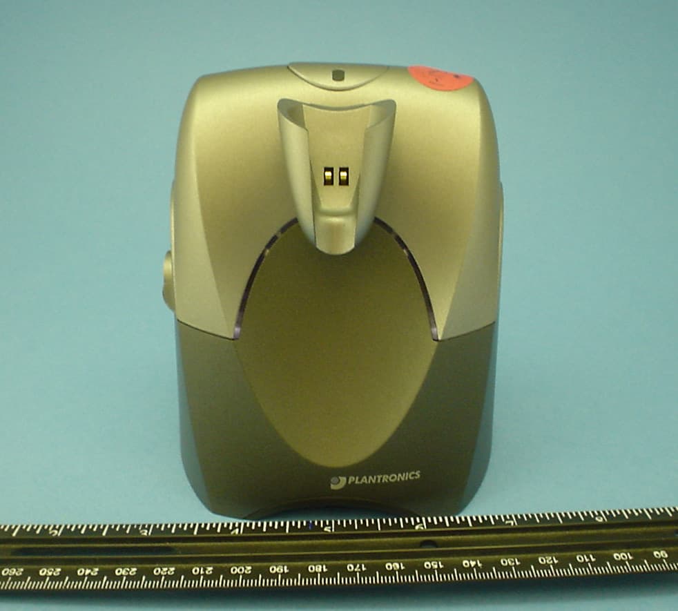
Click to zoom
Application Details
- Equipment Class
- PUB - Part 15 Unlicensed PCS Base Station
- Date of Grant
- Nov 10, 2005
- Application Purpose
- Original Equipment
- Date of Application
- Nov 10, 2005
- Equipment Note
- Wireless Telephone Adapter Base Station
- Frequency Range
- 1921.53600000 - 1928.44800000
- Company
- HP Inc.
- Country
- United States
Documents & Files
Document Text
Text extracted from the exhibit documents filed with the FCC. Open a document above to read the original.
Users Manual
p - 3 0 0 5 p - 3 0 0 5 WELCOME Thank youfor selecting the CS55 Micro™ Wireless Office Headset System from Plantronics. You have made the right choice for comfort and versatility. This system allows your telephone to use a cordless Plantronics headset through an adapting base. It offers hands-free convenience and long-range workspace mobility. With the use of an optional handset lifter, the user can r emotely receive the telephone’s ring alert and can answer the call by simply pushing the talk button on the headset. This side of the guide has Important Safety Information that should be read prior to set up and use of your system. The quick start part on the other side identifies the components, has five steps to get you started, and test the system. M ost telephones will work with little or no adjustments. This system is not designed to work with phones which hav e the dial pad built into the handset. The Product Information Booklet in all languages is online at: http:www.plantronics.com/documentation/ Choose your preferred language and the Plantronics model number “CS55 Micro™” to access complete user documentation including this Quick Start Guide and the Product Information Booklet which has more on the system’s o peration, adjustments, and troubleshooting. • Do not locate this product near water, for example, near a bathtub, or sink, in a w et basement, or near a swimming pool. • This pr oduct should ne v er be plac ed near or o ver a radiator or heat register. It should not be placed in a b uilt-in installation unless proper ventilation is provided. • Do not allow anything to rest on the power cord. Do not locate this product where persons walking on it will damage the c or d. • Do not overload outlets and extension cords as this c an r esult in risk of fir e or el ectric shock. • Never disassemble or push objects of any kind into the product since this may short out parts which could result in a fire or electric shock. Never spill liquid of any kind on the product. • Use caution when installing or modifying telephone lines. • A v oid using t el ephone equipment during an electrical s t orm. • Keep all product cords and cables away from operating machinery. • Do not use this equipment to report a gas leak while you are in the vicinity of a gas leak. • Ne v er all ow children to play with the headset/adapter– small parts may be a choking hazar d. • Unplug this product from the wall outlet before cleaning. Donot use liquid cleaners or aerosol cleaners. Use a damp cloth for cleaning. IMPORTANTSAFETYINFORMATION When using your telephone equipment these basic safety precautions and warnings should be followed to reduce the risk of fire, electric shock, and injury to persons. • Read and follow all instructions and warnings prior to using the product. The symbolidentifies and alerts the user to the presence of important operating, safety, and service instructions. • This product contains gold-plated nickel, phosphor bronze and copper. If you experience a skin irritation, discontinue use and contact Plantronics. • This product is intended to be powered by a Listed Class 2 Direct Plug-In Power Unit rated 9VDC at 800mA, Part No. 45561-02, rated at an input voltage of 120 VAC, 60Hz and an output voltage of 9 VDC at 800mA. • This product requires AC power in order to operate. During a power outage, have another telephone available that is powered only by the telephone line. BATTERYPRECAUTIONS T o reduce the risk of fire or injury to persons, read and f oll o wthese ins tructions. • Use only the battery pack supplied with this product, part number 64399-01. • Do not dispose of battery pack in a fire. The cells may explode. Check with local codes for disposal instructions. • Do not open or mutilate battery pack. Released electrolyte is corrosive and may cause damage to eyes or skin and may be toxic if swallowed. • Exercise care in handling the battery pack in order not to short the battery contacts with conducting materials such as rings, bracelets, and keys. The battery or conductor may o v erheat and c ause burns. • Charge the battery pack in accordance with instructions supplied with this unit. • Observ e pr oper orient ation betw een batt ery pack and charger contacts. • Batteries can be swallowed by children and are dangerous if swall o w ed. Al ways s t ore and dispose of batteries where children can’t reach them. SAV ETHESEINSTRUCTIONS WARNING FCC REQUIREMENTS PART15 This device complies with Part 15 of the FCC Rules. Operation is subject to the following two conditions: 1. This device may not cause harmful interference, and 2. This device must accept any interference received, including interference that may cause undesired operation. This equipment has been t es t ed and found to comply with the limits for a Class B digital device, pursuant t o Part 15 of the FCC Rules. These limits are designed to provide reasonable protection against harmful interference in a residential installation. This equipment generates, uses, and can radiate radio frequency ener gy and, if not installed and used in accordance with the instructions, may cause harmful interference to radio communications. However, there is no guarantee that interference will not occur in a particular installation. If this equipment does cause harmful interference to radio or television reception which can be determined by turning the radio or television off and on, the user is encouraged to try to correct interference by one or more of the following measures: 1.Reorient or relocate the receiving antenna. 2. Increase the separation between the equipment and receiver. 3. Connect the equipment into an outlet on another circuit. 4. Consult the dealer or an experienced radio/TV technician for help. EXPOSURE TO RADIOFREQUENCYRADIA TION This device and its antenna must not be co-located or operated in conjunction with any other antenna or tr ansmitt er . To comply with FCC RF exposure requirements, only use the supplied antenna. The r adi…
Text truncated - open the document above for the full version.
Cover Letter(s)
Regarding the request by Plantronics for Equipment Authorization for the CS55/CS55 Micro under the provisions of 47CFR15 Subpart D S. Cahill, Oct. 31st, 2005 Revised Nov. 10 2005: added exhibits #13 and #14, and corrected exhibit a and b references in extant exhibit listing. Revised Nov. 11 2005: separated product photos from exhibits #10a and #10b as exhibits #15a and #15b, and partitioned Exhibit #11a into Exhibit #11aa and Exhibit #11ab, to facilitate electronic transfers. To whom it may concern: Plantronics is providing the following exhibits in support of this request. Identifier and equipment class: AL8CS55XXXX Base - PUB, Unlicensed PCS base unit. AL8CS55YYYY Headset - PUE, Unlicensed PCS unit held to ear. Exhibit #1a, 1b: Letters of Confidentiality for the base and the headset. Exhibit #2: User’s Manual, with required text per part 15, p/n 70678 Exhibit #3a, 3b: Product label file detailing FCC ID number assignments for the base and the headset Exhibit #4: Theory of operation, CS55 base and headset Exhibit #5: Operational block diagrams, CS55 base and headset Exhibit #6a, 6b: Detailed schematics, CS55 base and headset Exhibit #7a, 7b: SAR test reports, CS55 base and headset, performed by Celltech Labs Exhibit #8a, 8b: External photographs, CS55 base and headset, both microphone arrangements Exhibit #9a, 9b: Internal photographs, CS55 base and headset Exhibit #10a, 10b: Certified Lab test reports prepared by Elliott Labs - A/C line conducted emissions and Class B Digital Device radiated emissions measurements and reports for the base and the headset with the microphone in two positions; at the user’s mouth, and with the microphone contained within the body of the headset, the tests labeled CS55 (#10a) and CS55 Micro (#10b), respectively. Exhibit #11a, 11b: Conducted test report, CS55 base and headset, according to the requirements for UPCS compliance, V3.3 (draft) of C63.17-2005, split into two sections for emailing under the 5Mbyte limit. Exhibit #12: UTAM membership affidavit Exhibit #13: SAR Probe Calibration report, the missing Appendix F of SAR test reports exhibits #7a and b. Exhibit #14: Response to SAR measurement question - 1g vs. 10g Celltech Response Letter Nov_10_05 Exhibit #15a, 15b: CS55 product photographs for tests of long and short-boom microphone configurations, taken during Certified Lab tests; appendixes C and D of Exhibits #10a and #10b. The following contacts are provided for response to inquiries: 1) Steve Cahill, 831-458-7512 - Principal RF Engineer [email protected] (technical) 2) Chris Brady, 831-458-7704 - Product Manager [email protected] (non-technical) Regards Steve Cahill
External Photos
AL8CS55XXXX external photographs in support of FCC filing S. Cahill, Oct. 31 st , 2005 AL8CS55XXXX, front view, headset not docked AL8CS55XXXX, back view, headset not docked AL8CS55XXXX underside showing FCC ID label position
Internal Photos
AL8CS55XXXX external photographs in support of FCC filing S. Cahill, Oct. 31 st , 2005 AL8CS55XXX internal view, front side. AL8CS55XXXX internal view, backside.
Test Report
File: R61281 September 23, 2005 Steve Cahill Plantronics 345 Encinal Street Santa Cruz, CA 95061-0635 Subject: FCC Emissions Report, CS55 Dear Mr. Cahill: A report has been created detailing the results of the FCC electromagnetic emissions testing performed on the CS55. Please find this report enclosed. Per Federal Communication Commission regulations, the signature of an official of the company responsible for marketing the CS55 is required, for this report, to be acceptable for determining compliance. We recommend filing this report in a safe place for future reference. Once an official has signed page 3 of this report, you may begin shipping the CS55. Each unit must be manufactured with any modifications described in the report, the proper FCC label should be attached and the appropriate FCC statement should be included in the operator's manual. If you have any questions, please don't hesitate to call us at 408-245-7800. Sincerely, Juan Martinez Senior EMC Engineer JM/dmg Enclosure: Emissions Report File: R61281 Page 1 of 15 Electromagnetic Emissions Test Report for Verification of Compliance per FCC Part 15, Subpart B Specifications for a Class B Digital Device and ICES-003 Class B and Subpart D – Unlicensed Personal Communications Devices on the Plantronics Model: CS55 MANUFACTURER: Plantronics 345 Encinal Street Santa Cruz, CA 95061-0635 TEST SITE: Elliott Laboratories, Inc. 684 W. Maude Avenue Sunnyvale, CA 94086 REPORT DATE: September 23, 2005 FINAL TEST DATES: September 15, September 16 and September 20, 2005 AUTHORIZED SIGNATORY: ______________________________ Juan Martinez Senior EMC Engineer Elliott Laboratories, Inc. is accredited by the A2LA, certificate number 2016-01, to perform the test(s) listed in this report. This report shall not be reproduced, except in its entirety, without the written approval of Elliott Laboratories, Inc. 2016-01 Elliott Laboratories, Inc. -- EMC Department Test Report Report Date: September 23, 2005 File: R61281 Page 2 of 15 Pages TABLE OF CONTENTS COVER PAGE................................................................................................................................................................................1 TABLE OF CONTENTS..............................................................................................................................................................2 SCOPE............................................................................................................................................................................................3 VALIDATING SIGNATURES.....................................................................................................................................................4 OBJECTIVE...................................................................................................................................................................................4 EMISSION TEST RESULTS.......................................................................................................................................................5 LIMITS OF CONDUCTED INTERFERENCE VOLTAGE.....................................................................................................5 LIMITS OF RADIATED INTERFERENCE FIELD STRENGTH..........................................................................................5 MEASUREMENT UNCERTAINTIES....................................................................................................................................6 EQUIPMENT UNDER TEST (EUT) DETAILS..........................................................................................................................7 GENERAL...................................................................................................................................................................................7 OTHER EUT DETAILS.............................................................................................................................................................7 ENCLOSURE..............................................................................................................................................................................7 MODIFICATIONS.....................................................................................................................................................................8 SUPPORT EQUIPMENT...........................................................................................................................................................8 EUT INTERFACE PORTS........................................................................................................................................................8 EUT OPERATION.....................................................................................................................................................................8 TEST SITE......................................................................................................................................................................................9 GENERAL INFORMATION.....................................................................................................................................................9 CONDUCTED EMISSIONS CONSIDERATIONS.................................................................................................................9 RADIATED EMISSIONS CONSIDERATIONS....................................................................................................................9 MEASUREMENT INSTRUMENTATION................................................................................................................................10 RECEIVER SYSTEM................................................................................................................................................................10 INSTRUMENT CONTROL COMPUT…
Text truncated - open the document above for the full version.
Test Report
File: R61282 September 23, 2005 Steve Cahill Plantronics 345 Encinal Street Santa Cruz, CA 95061-0635 Subject: FCC Emissions Report, CS55 Micro Dear Mr. Cahill: A report has been created detailing the results of the FCC electromagnetic emissions testing performed on the CS55 Micro. Please find this report enclosed. Per Federal Communication Commission regulations, the signature of an official of the company responsible for marketing the CS55 Micro is required, for this report, to be acceptable for determining compliance. We recommend filing this report in a safe place for future reference. Once an official has signed page 3 of this report, you may begin shipping the CS55 Micro. Each unit must be manufactured with any modifications described in the report, the proper FCC label should be attached and the appropriate FCC statement should be included in the operator's manual. If you have any questions, please don't hesitate to call us at 408-245-7800. Sincerely, Juan Martinez Senior EMC Engineer JM/dmg Enclosure: Emissions Report File: R61282 Page 1 of 15 Electromagnetic Emissions Test Report for Verification of Compliance per FCC Part 15, Subpart B Specifications for a Class B Digital Device and ICES-003 Class B and Subpart D – Unlicensed Personal Communications Devices on the Plantronics Model: CS55 Micro MANUFACTURER: Plantronics 345 Encinal Street Santa Cruz, CA 95061-0635 TEST SITE: Elliott Laboratories, Inc. 684 W. Maude Avenue Sunnyvale, CA 94086 REPORT DATE: September 23, 2005 FINAL TEST DATES: September 15, September 16 and September 20, 2005 AUTHORIZED SIGNATORY: ______________________________ Juan Martinez Senior EMC Engineer Elliott Laboratories, Inc. is accredited by the A2LA, certificate number 2016-01, to perform the test(s) listed in this report. This report shall not be reproduced, except in its entirety, without the written approval of Elliott Laboratories, Inc. 2016-01 Elliott Laboratories, Inc. -- EMC Department Test Report Report Date: September 23, 2005 File: R61282 Page 2 of 15 Pages TABLE OF CONTENTS COVER PAGE...................................................................................................................................................................................1 TABLE OF CONTENTS..............................................................................................................................................................2 SCOPE............................................................................................................................................................................................3 VALIDATING SIGNATURES.....................................................................................................................................................4 OBJECTIVE...................................................................................................................................................................................4 EMISSION TEST RESULTS.......................................................................................................................................................5 LIMITS OF CONDUCTED INTERFERENCE VOLTAGE.....................................................................................................5 LIMITS OF RADIATED INTERFERENCE FIELD STRENGTH..........................................................................................5 MEASUREMENT UNCERTAINTIES....................................................................................................................................6 EQUIPMENT UNDER TEST (EUT) DETAILS..........................................................................................................................7 GENERAL...................................................................................................................................................................................7 OTHER EUT DETAILS.............................................................................................................................................................7 ENCLOSURE..............................................................................................................................................................................7 MODIFICATIONS.....................................................................................................................................................................8 SUPPORT EQUIPMENT...........................................................................................................................................................8 EUT INTERFACE PORTS........................................................................................................................................................8 EUT OPERATION.....................................................................................................................................................................8 TEST SITE......................................................................................................................................................................................9 GENERAL INFORMATION.....................................................................................................................................................9 CONDUCTED EMISSIONS CONSIDERATIONS.................................................................................................................9 RADIATED EMISSIONS CONSIDERATIONS....................................................................................................................9 MEASUREMENT INSTRUMENTATION................................................................................................................................10 RECEIVER SYSTEM...........................................................................................................................................................…
Text truncated - open the document above for the full version.
Test Report
Exhibit #11 Conducted RF and spectral etiquette measurements to support the certification of the CS55/CS55 Micro base and headset, AL8CS55XXXX and AL8CS55YYYY. Plantronics, S. Cahill, October 28 2005. Contents: I) Background A. EUT description 2 B. Manufacturer’s mandatory declarations 3 C. Standard test configurations 6 D. Calibration 10 II) Test results summary A. Base EUT 16 B. Headset EUT 27 III) Tests of clause 6 performed by the manufacturer, for the base EUT A. Clause 6.1 Emissions tests for the base EUT 38 B. Clause 6.2 Tests of frequency and time stability for the base EUT 73 IV) Tests of clause 7, base EUT A. Clause 7.3.2 Upper threshold for EUTs which implement the LIC procedure, base EUT 82 B. Clause 7.3.3 Least interfered channel (LIC) procedure test, base EUT 84 C. Clause 7.3.4 Selected channel confirmation, base EUT 88 D. Clause 7.5 Reaction time and monitoring interval, base EUT 95 V) Tests of clause 8, base EUT A. Clause 8.1.1 Access criteria test interval, base EUT 105 B. Clause 8.1.2 Access criteria functional test (47CFR15.323(c)(6) not implemented), base EUT 110 C. Clause 8.2.1 Acknowledgements, base EUT 113 D. Clause 8.2.2 Transmission duration, base EUT 116 VI) Tests of clause 6 performed by the manufacturer, for the headset EUT A. Clause 6.1 Emissions tests for the headset EUT 117 B. Clause 6.2 Tests of frequency and time stability for the headset EUT 151 VII) Tests of clause 7, headset EUT A. Clause 7.3.2 Upper threshold for EUTs which implement the LIC procedure, headset EUT 160 B. Clause 7.3.3 Least interfered channel (LIC) procedure test, headset EUT 162 C. Clause 7.3.4 Selected channel confirmation, headset EUT 166 D. Clause 7.5 Reaction time and monitoring interval, headset EUT 169 VIII) Tests of clause 8, headset EUT A. Clause 8.2.1 Acknowledgements, headset EUT 173 B. Clause 8.2.2 Transmission duration, headset EUT 182 NOTE: pages 1 – 81 of this document are in Exhibit #11aa, pages 82 – 104 are in Exhibit #11ab, and pages 105 – 182 are in Exhibit #11b. Document was partitioned for ease of transfer. 1 I) Background I-A. EUT description The CS55 and CS55 Micro are headset telephone adapter devices. The devices comprise a wireless headset typically worn by the user, and a base unit which replaces a telephone handset in connection to a standard telephone. The telephone’s handset then plugs into the base unit. The base unit provides a docking cradle for charging the headset, and is provided with an AC power adapter. Other accessories (on-line indicator, telephone handset lifter) may be connected to the base unit at the end-user’s discretion. Both the headset and the base unit are intentional radiators, designed in accordance with the requirements of 47CFR15 subpart D. The CS55 and CS55 Micro headsets are essentially identical, differing in the headset only in cosmetics in the length of the boom, and placement and pattern of the microphone; the CS55 uses a directional noise-canceling microphone and the CS55 Micro uses an omni microphone. In the base, the CS55 and CS55 Micro differ only in the cosmetics of the cradle in which the headset is docked and charges. The specific units tested were base unit #185 and headset #1-5. 2 I-B. Manufacturer’s attestations, mandatory declarations and descriptions The CS55/CS55 Micro base and CS55/CS55 Micro headset use digital modulation. Clause 4.11 in V3.3 of (draft) C63.17-2005 requires the following declarations to be made by the manufacturer. These declarations are used in demonstrating compliance with certain sections of 47CFR15 subpart D, and in support of test parameters within V3.3 of (draft) C63.17-2005. The channel plan. Five RF carriers are used, as follows: 1928.448 MHz. 1926.720 MHz. 1924.992 MHz. 1923.264 MHz. 1921.536 MHz. Maximum EUT antenna gain GA (dBi), and orientation and polarization for maximum gain. The maximum headset EUT antenna gain is 3dBi. The antenna is elliptically polarized with the major axis of polarization normal to the external surface of the headset disposed away from the user’s head, and with the minor axis of polarization parallel to the length of the major axis of the headset. Two identical collocated antennas are provided for the base EUT, within the definition of V3.3 of (draft) C63.17-2005. The maximum base EUT antenna gain is 3dBi. The antennas are elliptically polarized with the major axis of polarization vertical from the top left and right corners of the base, and with the minor axis of polarization normal to the front and back surfaces of the base for left and right antennas. Maximum peak power level Maximum specified peak conducted power level for both the base and the headset EUTs is +10dBm. Emission bandwidth Emission bandwidth measured according to the procedures of V3.3 (draft) C63.17-2005 clause 6.1.3 for the base EUT is 1.48MHz. Emission bandwidth measured according to the procedures of V3.3 (draft) C63.17-2005 clause 6.1.3 for the headset EUT is 1.49MHz. Nominal receive bandwidth Nominal receive bandwidth is +/-500kHz. 3 Frame period and time slot plan, if TDMA techniques are used The EUT system is a TDMA system which “further divides access in time” in the context of clause 6.2.2 of V3.3 (draft) C63.17-2005. Frame period is 10mS. There are 24 timeslots per frame, with one of the first 12 timeslots used for the headset transmissions and one of the last 12 timeslots used for the base transmissions. Transmit and receive timeslots are 5mS apart in time. Transient events occur during which two non-adjacent timeslots may be in use by the base during the setup of the communications channel, or by both the base and the headset EUT as the system does a soft handoff in response to interference. Minimum and maximum burst length, if TDMA techniques are used Minimum burst length is 90uS, the beacon transmissions from the base when a communications channel is not open. Maximum burst length is 390uS, transmissions from the headset when a communications channel is open. Minimum and maximu…
Text truncated - open the document above for the full version.
Test Report
Pages 1 – 81 of this document are in Exhibit #11aa, and pages 105 – 182 are in Exhibit #11b. Partitioning was necessary in order to facilitate file transfer. IV) Tests of clause 7, base EUT IV-A. Clause 7.3.2 Upper threshold for EUTs which implement the LIC procedure, base EUT The test platform, base EUT and companion headset are configured according to the requirements for implementing the test of 7.3.2(b) by means of test configuration #5, With companion device and interference blocking, base EUT, of section (I) of this document. The multi-carrier interference generator (PXI-5670) is set to CW on all 5 carriers, and at level -35.5dBm, which is T U + U M + 10dB, where TU = -51.5dBm from the manufacturer’s declarations and the measured emissions bandwidth and UM is defined in V3.3 (draft) C63.17-2005 as 6dB. The transmit spectrum and interference spectrum are observed using the E4407B spectrum analyzer. Trigger is free-run, detection is peak, otherwise adjustments are as shown on the screenshot following. A trace (yellow) is captured and held at the initial interference setting of -35.5dBm. The multi-carrier interference generator level is then reduced incrementally in 1dB steps until the base EUT begins to transmit the beacon. A max-hold signal (purple) captures the trace showing when transmissions of the beacon begin. For each 1dB step, the base EUT is powered down while the multi-carrier interference generator is set to the new level. A trace (blue) shows the interference carrier level at the level where transmissions first begin. A marker shows the delta between the -35.5dBm level and the level at which transmissions first begin. Fig. 49 - Emissions and interference profile spectrum, base EUT, test 7.3.2. 82 83 A trace (yellow, 2 nd from top, fig. 49) is captured and held at the initial interference level setting of -35.5dBm. Then the multi-carrier interference generator level is reduced incrementally in 1dB steps until the base EUT begins to transmit the beacon. A max-hold signal (purple, top) captures the trace showing when transmissions of the beacon begin. A trace (blue, bottom) shows the interference carrier level at the level where transmissions first begin. A marker shows the delta between the -35.5dBm level and the level at which transmissions first begin. For each 1dB step of reduced interference level, the base EUT is powered down while the multi-carrier interference generator is set to the new level. The first interference level at which the base EUT transmits is -48.5dBm. The allowed upper limit is T U + UM = - 45.5dBm, the base EUT passes. Note that absolute level at the spectrum analyzer and displayed above is a consequence of the relative losses between the EUT port of the combining network and the spectrum analyzer port, relative to the multi-carrier generator port. IV-B. Clause 7.3.3 Least interfered channel (LIC) procedure test, base EUT The test platform, base E…
Text truncated - open the document above for the full version.
Contact Information
Applicant
Richard Tarsio(US/CAN TRSE Worldwide Technical Regulations)
Technical Contact
PCTEST Engineering Laboratory, Inc.Randy Ortanez
[email protected]410-290-6652
6660-B Dobbin Road · Columbia, Maryland · United States
Test Firm
Celltech Labs Inc.Ben Hewson
Technical Specifications
| # | Rule Parts | Frequency Range | Power Output |
|---|---|---|---|
| 1 | 15D | 1.92 GHz - 1.93 GHz | 7.00 mW |
Other Applications from HP Inc.
AL8-PWPTF620P
Feb 03, 2026Wireless Charge Stand
Equipment Class
DCD - Part 15 Low Power Transmitter Below 1705 kHzAL8-PBF620F
Jan 23, 2026Bluetooth Headset
Equipment Class
DTS - Digital Transmission SystemAL8-PBVOYX2
Jun 20, 2024Bluetooth Base
Equipment Class
DTS - Digital Transmission System
AL8-VF2R
Mar 07, 2024Wireless Bluetooth Earphones
Equipment Class
DTS - Digital Transmission System
AL8-CBVS1
Oct 16, 2023Wireless Charge Stand
Equipment Class
DXX - Part 15 Low Power Communication Device Transmitter