AL8CS7YYYYWireless Office System Headset
HP Inc.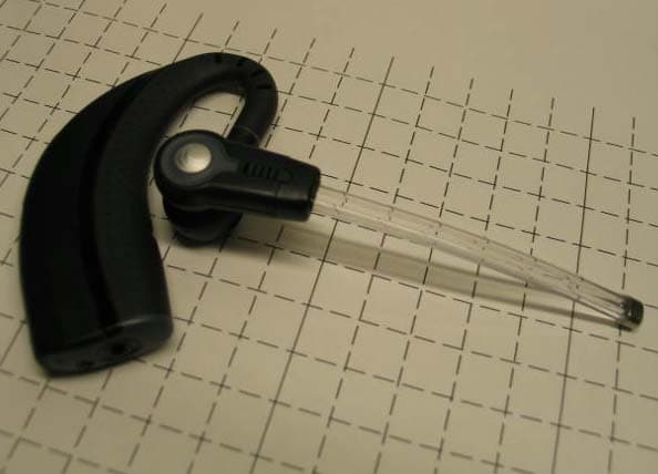
Click to zoom
Application Details
- Equipment Class
- PUE - Part 15 Unlicensed PCS portable Tx held to ear
- Date of Grant
- Feb 21, 2006
- Application Purpose
- Original Equipment
- Date of Application
- Feb 21, 2006
- Equipment Note
- Wireless Office System Headset
- Frequency Range
- 1921.53600000 - 1928.44800000
- Company
- HP Inc.
- Country
- United States
Documents & Files
Document Text
Text extracted from the exhibit documents filed with the FCC. Open a document above to read the original.
Users Manual
SOUND INNOVATION ©2005 Plantronics, Inc. All rights reserved. Plantronics, the logo design, IntelliStand, Plantronics Sound Innovation, and the voice tube clear color and shape trade dress are trademarks or registered trademarks of Plantronics, Inc. All other trademarks are the property of their respective owners. Patents U.S. 6,735,453; Patents Pending Printed in China. 72535-01 (12.05) WARRANTY USER GUIDE_ CS70 ....................................................................... WIRELESS OFFICE HEADSET SYSTEM Limited Warranty • This warranty covers defects in materials and workmanship of products manufactured, sold or certified by Plantronics which were purchased and used in the United States. • This warranty lasts for one year from the date of purchase of the products. • This warranty extends to you only if you are the end user with the original purchase receipt. • We will, at our option, repair or replace the products that do not conform to the warranty. We may use functionally equivalent reconditioned/refurbished/ remanufactured/pre-owned or new products or parts. • To obtain service in the U.S., contact Plantronics at (800) 544-4660 ext. 5538. • THIS IS PLANTRONICS’ COMPLETE WARRANTY FOR THE PRODUCTS. • This warranty gives you specific legal rights, and you may also have other rights that vary from state to state. Please contact your dealer or our service center for the full details of our limited warranty, including items not covered by this limited warranty. The Plantronics Technical Assistance Center is ready to assist you! Dial (800) 544-4660 ext. 5538, or visit the support section of our website at www.plantronics.com/support. TECHNICAL ASSISTANCE MAINTENANCE 1. Unplug the unit from the telephone and the AC charger from the power source before cleaning. 2. Clean the equipment with a damp (not wet) cloth. 3. Do not use solvents or other cleaning agents. 3 2 PACKAGE CONTENTS Telephone Cord Eartips AC Charger Handset Lifter (Optional) Handset Lifter Base Headset Ringer Microphone Extender Arm with Stabilizers ForNortel i2004 phones only Additional parts (ifrequired). Details on page 22. TABLE OF CONTENTS Package Contents Features Setup Positioning Adjusting Fit Charging CheckingCompatibility 3 4 6 9 9 8 12 Making/Answering/Ending Calls 10 Multi-shift Pairing 11 Headset Controls Volume 17 Setup – Handset Lifter (Optional) 15 14 Troubleshooting 19 Base Indicator Lights 18 Battery Replacement 21 Subscription 20 21 System Reset 22 Additional Parts (if required) Regulatory Notices 23 Visit www.plantronics.com/productregistrationto register your product online so we can provide you with the best possible service and technical support. Register Your Product Online 5 4 FEATURESFEATURES Listening Volume/Mute Talk Indicator Light Call Control Button Voice Tube Microphone Lifter Arm Ringer Microphone Jack (remove cover) Height Switch Accessory Jack Power Cord Headset Handset Lifter Charging Cradle Front: Indicator Lights Talk (Green) Power (Red) Charge (Amber) Telephone Configuration Dial Rear: Listening Volume Major Adjust Telephone Cord IntelliStand On/Off Switch (to automate call control button) Speaking Volume Minor Adjust Base - Top View Base - Bottom View Telephone Cord Jack Telephone Handset Jack Speaking Volume Major Adjust AC Charging Jack Lifter Jack Listening Volume/Mute Talk Indicator Light Call Control Button Voice Tube Microphone Lifter Arm Ringer Microphone Jack (remove cover) Height Switch Accessory Jack Power Cord Headset Handset Lifter Charging Cradle Front: Indicator Lights Talk (Green) Power (Red) Charge (Amber) Telephone Configuration Dial Rear: Listening Volume Major Adjust Telephone Cord IntelliStand On/Off Switch (to automate call control button) Speaking Volume Minor Adjust Base - Top View Base - Bottom View Telephone Cord Jack Telephone Handset Jack Speaking Volume Major Adjust AC Charging Jack Lifter Jack 7 6 3A 4A D C Complete Base - Bottom View ! 9 v A D B C SETUP Plug the AC charger into the base’s AC charging jack. Push in firmly. Plug the handset cord into the handset jack in the base. Push in until it clicks. 2 SETUP 1 Unplug the handset cord from phone.Plug the phone cord that is connected to the CS70 base into the handset jack on the phone. CAUTION: Your phone may have two similar jacks. Put the cord only in the jack from which the handset came. Plug the AC charger into an outlet and into the base’s AC charging jack. See step 4 4 A A for detailed location. 4 3 Plug the handset cord into the handset jack in the bottom of the base. See step 3 3 A A for detailed location. NOTE: The access to the handset jack is fairly small. If you have large hands you may want to ask someone with smaller fingers to do this step. 9 8 6 ” 1 2 ” The m m i i n n i i m m u u m m recommended separation distance is shown above. IMPORTANT:Incorrect positioning can cause noise and interference problems. CHARGING 2 1 POSITIONING 1. Slide headset into charging cradle; the earpiece with the microphone goes into the cradle. 2. Gently press down on the headset to ensure that headset is in correct position. Amber charge indicator light on base will flash while charging and will change to solid amber when fully charged. • 20 minutes = minimum charge to continue setup • 3 hours = full charge SETUP — HANDSET LIFTER (OPTIONAL) 3 IntelliStand ™ off IntelliStand on Set the IntelliStand switch to Intellistand off ( –) if you want to control the handset lifter with the call control button on your headset. Set the Intellistand switch to Intellistand on ( =)if you want the handset to automatically pick up when you take the headset off the charging cradle. 21 1. Plug handset lifter power cord into handset lifter jack on base. Push firmly into base. 2. Position handset lifter under the handset on your phone. Verify that the lifter is located on top of the telephone speaker. If not, you will need to attach the ringer microphone as described on page 22. NOTE: Remove only a tiny piece of mounting tape…
Text truncated - open the document above for the full version.
Attestation Statements
Attn: Reviewing Engineer Federal Communications Commission 7435 Oakland Mills Road Columbia, MD 21046 January 10, 2006 RE: Confidentiality Request for AL8CS7YYYY headset To Whom It May Concern: This letter serves as an official request for confidentiality under FCC Rule Section 0.459. We request that: 1) Exhibit 6x; all schematic diagrams 2) Exhibit 5 the detailed block diagram 3) Exhibit 4 the detailed theory of operation required to be submitted with this application be withheld from public review. These documents are company proprietary information that is not publicly available, and would damage Plantronics’ commercial interests if made public. Please contact me if there is any information that you may need. Regards John Mihelic Electrical Engineer Plantronics [email protected]
Cover Letter(s)
Regarding the request by Plantronics for Equipment Authorization for the CS70 and CS70N headset under the provisions of 47CFR15 Subpart D John Mihelic, Jan 10, 2006 To whom it may concern: Plantronics is providing the following exhibits in support of this request. Identifier and equipment class: AL8CS7YYYY Headset - PUE, Unlicensed PCS unit held to ear. Exhibit #1: Letter of Confidentiality for the headsets. Exhibit #2: User’s Manual, with required text per part 15 Exhibit #3, 3a: Product label file detailing FCC ID number and model label assignments for the headset Exhibit #4: Theory of operation, CS70, and CS70N headset and AL8CS7YYYY accompanying base Exhibit #5: Operational block diagrams, CS70, and CS70N headset Exhibit #6: Detailed schematic, CS70 and CS70N are electronically identical and use the same schematic Exhibit #7a: SAR test reports, CS70, and CS70N headset and SAR System Validation by Celltech Labs. Exhibit #7b: SAR Probe Calibration reported by Celltech Labs Exhibit #8: External photographs, CS70, and CS70N headset Exhibit #9: Internal photographs, common electrical board for CS70, and CS70N headset Exhibit #10a, 10b: Certified Lab test reports prepared by Elliott Labs - A/C line conducted emissions and Class B Digital Device radiated emissions measurements and reports for CS70 (Exhibit 10a), and CS70N (Exhibit 10b) Exhibit #11: Conducted test report, CS70, and CS70N headset, according to the requirements for UPCS compliance, V3.3 (draft) of C63.17-2005. Exhibit #12: UTAM membership affidavit Exhibit #13: Data Sheet to be posted on company website http://www.plantronics.com The following contacts are provided for response to inquiries: 1) Steve Evans, 831-458-7441 - RF Engineer [email protected] (technical) 2) Blanca Piedra, 831-458-7512 – Product Assurance Engineer [email protected] (compliance technical logistic) 3) Chris Brady, 831-458-7704 - Product Manager [email protected] (non-technical) Regards, John Mihelic Electrical Engineer
Cover Letter(s)
March 29, 2006 Federal Communications Commission Equipment Approval Services 7435 Oakland Mills Road Columbia, MD 21046 Attn: Mr. Martin Perrine SUBJECT: Plantronics Inc. FCC ID: AL8CS7YYYY 731 Confirmation No.: TC687773 Correspondence Reference No.: 27388 Request for Tech. Info.: 03/28/2006 Dear Steven: Transmitted herewith, on behalf of Plantronics Inc. is an amendment provided in response to the request for technical information dated March 28, 2006. 1. Please find attached the UTAM Affidavit, which was mentioned and required in the filing. We trust this information is sufficient to resolve FCC questions in this application. If you have any further questions, please do not hesitate to contact us. cc: Plantronics Inc.
External Photos
Plantronics Confidential AL8CS7YYYY external photographs in support of FCC filing B.Piedra, Jan.26/2006 CS70 Voice Tube: Laser marking at the back area of the voice tube microphone to place the FCC ID # and Model CS70N Noise Cancelling: Laser marking at the back area of the noise canceling microphone to place the FCC ID # and Model
ID Label/Location Info
Plantronics CS80 Made in China Plantronics CS70 Made in China FCC ID: AL8CS7YYYY Plantronics CS70 Made in China FCC ID: AL8CS7YYYY Plantronics CS80 Made in China 2672594 laser etchingCS70/80 Laser etching- voice tube variant m.bentley 26jan05 70181-XX 1:1 Placement reference 1:1 Placement reference 1:1 Laser etch 1:1 Laser etch 72594-02 (EMEA) 72594-01 (US) © 2005 ARTMASTER #: REV. LEVEL: REF. PART #: DESCRIPTION: PREPARED BY:DATE: PROCESS:
Internal Photos
Plantronics Confidential Internal Pictures AL8CS7YYYY internal photographs in support of FCC filing B. Piedra Jan 26, 2006 CS70N from side CS70N back side Plantronics Confidential CS70 front side CS70 back side
RF Exposure Info
Applicant: Plantronics Inc. FCC ID: AL8CS7YYYY Freq.:1921.536 - 1928.448 MHz Model(s): CS70, CS70NDUT Type: Wireless Office Headset System (UPCS Headset) 2006 Celltech Labs Inc. This document is not to be reproduced in whole or in part without the prior written permission of Celltech Labs Inc. Page 1 of 41 Test Report Serial No.: 122205AL8-T710-S15T Report Issue Date: January 10, 2006 Date(s) of Evaluation: January 03, 2006 Report Issue No.: S710-011006-R1 Description of Test(s): RF Exposure SARFCC 47 CFR §2.1093 IC RSS-102 Issue 2 Test Report Prepared By: Cheri Frangiadakis Test Report Writer Celltech Labs Inc. Test Report Approved By: Jonathan Hughes General Manager Celltech Labs Inc. RF EXPOSURE EVALUATION SPECIFIC ABSORPTION RATE SAR TEST REPORT FOR PLANTRONICS INC. WIRELESS HEADSET SYSTEM (UPCS) FCC ID: AL8CS7YYYY Test Report Serial Number 122205AL8-T710-S15T Test Report Issue Number S710-011006-R1 Test Lab Celltech Compliance Testing & Engineering Lab (Celltech Labs Inc.) 1955 Moss Court Kelowna, BC Canada V1Y 9L3 MODEL(S) DESCRIPTION CS70HeadsetVoice Tube CS70NHeadsetNoise Canceling Applicant: Plantronics Inc. FCC ID: AL8CS7YYYY Freq.:1921.536 - 1928.448 MHz Model(s): CS70, CS70NDUT Type: Wireless Office Headset System (UPCS Headset) 2006 Celltech Labs Inc. This document is not to be reproduced in whole or in part without the prior written permission of Celltech Labs Inc. Page 2 of 41 Test Report Serial No.: 122205AL8-T710-S15T Report Issue Date: January 10, 2006 Date(s) of Evaluation: January 03, 2006 Report Issue No.: S710-011006-R1 Description of Test(s): RF Exposure SARFCC 47 CFR §2.1093 IC RSS-102 Issue 2 DECLARATION OF COMPLIANCE SAR RF EXPOSURE EVALUATION Test Lab CELLTECH LABS INC. Testing and Engineering Services 1955 Moss Court Kelowna, B.C. Canada V1Y 9L3 Phone: 250-448-7047 Fax: 250-448-7046 e-mail: [email protected] web site: www.celltechlabs.com Applicant Information PLANTRONICS INC. 345 Encinal Street Santa Cruz, CA 95060 United States FCC ID: AL8CS7YYYY Model(s): CS70 (Voice Tube) CS70N (Noise Canceling) Rule Part(s): FCC 47 CFR §2.1093; IC RSS-102 Issue 2 Test Procedure(s): FCC OET Bulletin 65, Supplement C (01-01) IEEE 1525-2003 Device Classification: Part 15 Unlicensed PCS portable Tx held to ear (PUE) Device Description: Wireless Office Headset System (UPCS) Mode of Operation: TDMA (Time Division Multiple Access) Tx Frequency Range(s): 1921.536 - 1928.448 MHz RF Output Power Tested: 6.44 dBm (4.41 mW) Peak Conducted (CS70) 6.44 dBm (4.41 mW) Peak Conducted (CS70N) Max. Duty Cycle Tested: 8.3% Source-Based Time-Averaged (Crest Factor: 1:12.05) Antenna Type(s) Tested: Internal Battery Type(s) Tested: Lithium-ion Polymer 3.7 V Max. SAR Level(s) Evaluated: Head: 0.005 W/kg (Peak SAR measured from Area Scan) Celltech Labs Inc. declares under its sole responsibility that this wireless portable device is compliant with the Specific Absorption Rate (SAR) RF exposure requirements specified in FCC 47 CFR §2.1093 and Health Canada’s Safety Code 6. The device was tested in accordance with the measurement standards and procedures specified in FCC OET Bulletin 65, Supplement C (Edition 01-01), Industry Canada RSS-102 Issue 2 and IEEE Standard 1528-2003 for the General Population / Uncontrolled Exposure environment. All measurements were performed in accordance with the SAR system manufacturer recommendations. I attest to the accuracy of data. All measurements were performed by me or were made under my supervision and are correct to the best of my knowledge and belief. I assume full responsibility for the completeness of these measurements and vouch for the qualifications of all persons taking them. This test report shall not be reproduced partially, or in full, without the prior written approval of Celltech Labs Inc. The results and statements contained in this report pertain only to the device(s) evaluated. Tested By: Sean Johnston Compliance Technologist Celltech Labs Inc. Reviewed By: Spencer Watson Senior Compliance Technologist Celltech Labs Inc. Applicant: Plantronics Inc. FCC ID: AL8CS7YYYY Freq.:1921.536 - 1928.448 MHz Model(s): CS70, CS70NDUT Type: Wireless Office Headset System (UPCS Headset) 2006 Celltech Labs Inc. This document is not to be reproduced in whole or in part without the prior written permission of Celltech Labs Inc. Page 3 of 41 Test Report Serial No.: 122205AL8-T710-S15T Report Issue Date: January 10, 2006 Date(s) of Evaluation: January 03, 2006 Report Issue No.: S710-011006-R1 Description of Test(s): RF Exposure SARFCC 47 CFR §2.1093 IC RSS-102 Issue 2 TABLE OF CONTENTS 1.0 INTRODUCTION___________________________________________________________________ 4 2.0 DESCRIPTION OF DEVICE UNDER TEST (DUT) _________________________________________ 4 3.0 SAR MEASUREMENT SYSTEM _______________________________________________________ 5 4.0 MEASUREMENT SUMMARY _________________________________________________________ 6 5.0 DETAILS OF SAR EVALUATION ______________________________________________________ 7 6.0 EVALUATION PROCEDURES ________________________________________________________ 8 7.0 SYSTEM PERFORMANCE CHECK ___________________________________________________ 10 8.0 SIMULATED EQUIVALENT TISSUES _________________________________________________ 11 9.0 SAR SAFETY LIMITS ______________________________________________________________ 11 10.0 ROBOT SYSTEM SPECIFICATIONS _________________________________________________ 12 11.0 PROBE SPECIFICATION (ET3DV6) __________________________________________________ 13 12.0 SAM PHANTOM V4.0C ____________________________________________________________ 13 13.0 DEVICE HOLDER ________________________________________________________________ 13 14.0 TEST EQUIPMENT LIST ___________________________________________________________ 14 15.0 MEASUREMENT UNCERTAINTIES __________________________________________________ 15 16.0 REFERENCES ___________________________________________________________________ 17 APPENDIX A - SAR MEAS…
Text truncated - open the document above for the full version.
Test Report
1/94 Exhibit #11 Conducted RF and spectral etiquette measurements to support the certification of the CS70 and CS70N, FCC ID AL8CS7YYYY. Plantronics, John Mihelic, January 10 2006. I. Background 2 A. EUT description 2 B. Manufacturer’s attestations, mandatory declarations and descriptions 2 C. Standard test configurations 4 D. Calibration 7 II. Test Results Summary Headset EUT 12 III. Tests of clause 6, headset EUT 23 A. Clause 6.1 Emissions tests for the headset EUT 23 B. Clause 6.2 Tests of frequency and time stability for the headset EUT 57 IV. Tests of clause 7, headset EUT 64 A. Clause 7.3.2 Upper threshold for EUTs which implement the LIC procedure, headset EUT 64 B. Clause 7.3.3 Least interfered channel (LIC) procedure test, headset EUT 65 C. Clause 7.3.4 Selected channel confirmation, headset EUT 69 D. Clause 7.5 Reaction time and monitoring interval, headset EUT 72 V. Tests of clause 8, headset EUT 85 A. Clause 8.2.1 Acknowledgements, headset EUT 85 B. Clause 8.2.2 Transmission duration, headset EUT 94 2/94 I. Background A. EUT description The CS70 and CS70N headsets are essentially two electrically identical headsets differing only in the kind of microphone boom assembly. There is a voice tube boom assembly with an omnidirectional microphone and a noise canceling boom assembly with a directional noise canceling microphone. This document reports compliance of the headset to the test parameters of V3.3 of (draft) C63.17-2005. B. Manufacturer’s attestations, mandatory declarations and descriptions The CS70 and CS70N headsets use digital modulation. Clause 4.11 in V3.3 of (draft) C63.17-2005 requires the following declarations to be made by the manufacturer. These declarations are used in demonstrating compliance with certain sections of 47CFR15 subpart D, and in support of test parameters within V3.3 of (draft) C63.17-2005. The channel plan. Five RF carriers are used, as follows: 1928.448 MHz. 1926.720 MHz. 1924.992 MHz. 1923.264 MHz. 1921.536 MHz. Maximum EUT antenna gain GA (dBi), and orientation and polarization for maximum gain. The maximum headset EUT antenna gain is 3dBi. The antenna is elliptically polarized with the major axis of polarization parallel to the headband portion of the headset disposed away from the user’s head, and with the minor axis of polarization on the same plane as the electrical board and perpendicular headband portion of the headset. Maximum peak power level Maximum specified peak conducted power level for the headset EUTs is +10dBm. Emission bandwidth Emission bandwidth measured according to the procedures of V3.3 (draft) C63.17-2005 clause 6.1.3 for the headset EUT is 1.49MHz. Nominal receive bandwidth Nominal receive bandwidth is +/-500kHz. Frame period and time slot plan, if TDMA techniques are used The EUT system is a TDMA system which “further divides access in time” in the context of clause 6.2.2 of V3.3 (draft) C63.17-2005. Frame period is 10mS. There are 24 timeslots per frame, with one of the first 12 timeslots used for the headset transmissions and one of the last 12 timeslots used for the base transmissions. Transmit and receive timeslots are 5mS apart in time. Transient events occur during which two non-adjacent timeslots may be in use by the base during the setup of the communications channel, or by both the base and the headset EUT as the system does a soft handoff in response to interference. Minimum and maximum burst length, if TDMA techniques are used Maximum burst length is 390uS, transmissions from the headset when a communications channel is open. 3/94 Minimum and maximum operating temperature range declared to the end-user The minimum operating temperature is +4C. The maximum operating temperature is +44C. Whether a system built with the EUT does or does not operate under the provisions of 47CFR15.323(c)(10) to test for deferral only in conjunction with a companion device The EUT system does not use the provisions of 47CFR15.323(c)(10) to enable testing for access criteria only in one element of the system. The headset EUTs implement the access criteria tests. Whether a system built with the EUT does or does not implement the provisions of 47CFR15.323(c)(5) enabling the use of the upper threshold for deferral The EUT system does implement the provisions of 47CFR15.323(c)(5), and uses the upper threshold for deferral. The nominal value of the deferral threshold The nominal value of the deferral threshold implemented in the headset EUTs is -51.5dBm. This is obtained from clause 4.3.3 of V3.3 (draft) C63.17-2005, where B = 1.49 MHz as declared for the headset, P max (from clause 4.3.1) is 20.8dBm, and P EUT is 10dBm, maximum, as declared. Whether a system built using the EUT does or does not operate under the provisions of 47CFR15.323(c)(6) incorporating provisions for waiting for a channel to go clear The EUT system does not use the provisions of 47CFR15.323(c)(6) to enable access to a particular channel when that channel goes clear. Whether a system built using the EUT does or does not operate under the provisions of 47CFR15.323(c)(11) enabling the access criteria check on the receive channel while in the presence of collocated interferers The EUT system does not use the provisions of 47CFR15.323(c)(11) to enable the monitoring of a time and spectrum window blocked by a co-located transmitter. The provisions within the EUT for self-check, by which compliance with 47CFR15.319(f) is obtained The headset EUT incorporates the following provisions by which compliance with 47CFR15.319(f) is obtained: a. On powerup the unit will perform a self-test of permanent storage memory (ROM) by means of a sum/checksum validation. b. On powerup the unit will perform a self-test of critical EEPROM settings (those which if in error could result in performance outside the UPCS specification limits) by means of a sum/checksum validation. c. On powerup the unit will perform a self-test of RAM by means of a memory field write/readback/invert/write/readba…
Text truncated - open the document above for the full version.
Test Report
48/94 Fig. 29 – headset EUT out-of-band emissions in the region around the 3rd harmonic, with the headset EUT transmitting on the lowest carrier, 1921.536MHz. This measurement was made according to the requirements of the text of 6.1.6, and, with the worst-case peak at –46.86dB, shows margin to the -39.5dBm specification of 7.3dB. 49/94 Fig. 30 – headset EUT out-of-band emissions in the region around the 4th harmonic, with the headset EUT transmitting on the lowest carrier, 1921.536MHz, shows greater than 25dB of margin from the -39.5dBm specification limit. 50/94 Fig. 31 – headset EUT out-of-band emissions showing the regions from DC to 5MHz, with the transmitter using the highest carrier, 1928.448MHz. This screenshot resolves the contribution made by the spectrum analyzer’s DC response. Headset EUT margin to the -39.5dBm out-of-band emissions specification exceeds 25dB in this region 51/94 Fig. 32 – headset EUT out-of-band emissions showing the region from 5MHz to 1915MHz, with the transmitter using the highest carrier, 1928.448MHz. This screenshot shows a sweep made with resolution bandwidth increased to 100kHz to improve sweep time. Headset EUT emissions at –54.42dB have margin to the -39.5dBm out-of-band emissions specification in this spectral region of 14.92dB in this region, even measured in a 10x-wider bandwidth than that of the text of the test procedure in clause 6.1.6. 52/94 Fig. 33 – headset EUT out-of-band emissions showing the regions from bandedge to -1.25MHz, and from -1.25MHz to -2.5MHz, with the headset EUT transmitting on the highest carrier, 1928.448MHz. Margins to the specification of -9.5dBm in the region from bandedge to -1.25MHz, to the specification of -29.5dBm in the region from -1.25MHz to -2.5MHz, and to the specification of -39.5dBm in the region outside -2.5MHz from the bandedge all exceed 25dB. 53/94 Fig. 34 – headset EUT out-of-band emissions showing the regions from bandedge to +1.25MHz, and from +1.25MHz to +2.5MHz, with the headset EUT transmitting on the highest carrier, 1928.448MHz. Margin to the specification of -9.5dBm in the region from bandedge to +1.25MHz is found at marker 1, at –57.60dBm, and is 48.10dBm. Margin to the specification of -29.5dBm in the region from +1.25MHz to +2.5MHz is found at marker 2, at –65.27dBm, and is 35.77dB. Margin to the specification of -39.5dBm in the region outside +2.5MHz from the bandedge exceeds 25dB 54/94 Fig. 35 – headset EUT out-of-band emissions including the regions from 1935MHz to 19.3GHz with the headset EUT transmitting on the highest carrier, 1928.448MHz. The measurement is noise-limited. The 300kHz resolution bandwidth was used in the interests of getting a manageable sweep time, 1736.5 seconds, but the 300kHz bandwidth passes considerably more unwanted emissions than the 10kHz obtained from the text of v3.3 (draft) C63.17-2005 clause 6.1.6. The expanded resolution bandwidth measurement shows the 3 rd and 4 th harmonics as frequencies that need detailed emissions measurements recorded with the proper resolution bandwidth setting, and no other spurious frequencies are close to the emissions limit. We can then re-do the test using narrow scans according to the requirements of 6.1.6 to record the level per the v3.3 (draft) C63.17-2005 clause 6.1.6 specification. 55/94 Fig. 36 – headset EUT out-of-band emissions in the region around the 3rd harmonic, with the headset EUT transmitting on the highest carrier, 1928.448MHz. This measurement was made according to the requirements of the text of 6.1.6, and, with the worst-case peak at –48.37dB, shows margin to the -39.5dBm specification of 8.87dB. 56/94 Fig. 37 – headset EUT out-of-band emissions in the region around the 4th harmonic, with the headset EUT transmitting on the highest carrier, 1928.448MHz. This measurement was made according to the requirements of the text of 6.1.6, and, with the worst-case peak at –65.70dB, shows margin to the -39.5dBm specification of 26.2dB. 57/94 B. Clause 6.2 Tests of frequency and time stability for the headset EUT The test configuration for the tests of V3.3 (draft) C63.17-2005 clauses 6.2.1.1 through 6.2.1.3 and 6.2.1 through 6.2.3 for the headset EUT is as follows: The test platform and headset EUT are configured according to test configuration #2, Standard-specific tester, headset EUT, of section (I) of this document. The CMD60 is configured to report frequency offset with modulation removed, per the general requirements of 6.2.1. The number of transmit slots over which the measurement is made by the CMD60 is adjusted using the CONFIG MENU/TX TEST/MODULATION keystroke path. Set the number to 100 slots (bursts) to capture one second of signal, since there are 100 bursts per second, to generate one measurement of the mean value of the carrier frequency. The CMD60 measurement system calculates the mean value over each 100-slot measurement. The fixed channel used during the tests is the middle carrier, 1924.992MHz. The particularities associated with the tests for each clause are discussed in the specific test report sections, following. 58/94 Fig. 38 - Headset EUT within the temperature chamber, with RF connection to EUT and with power/control cable connection to EUT. 59/94 Fig. 39 - Detail of headset EUT as tested within the temperature chamber for the tests of clause 6.2. 60/94 Clause 6.2.1 Carrier frequency stability, headset EUT. Clause 6.2.1.1 for the headset EUT; mean carrier frequency drift with time. The headset EUT is configured as described in the introduction for the tests of clause 6.2. The EUT power supply voltage is set to 3.70V. Ambient for the EUT is set to 20C. The data collection system runs for one hour, collecting mean carrier frequency measurements and recording the peak and mean values. Fig. 40 - Measured one-second mean carrier frequency, headset EUT, and observed maximum, average value and observed minimum of the mean carrier frequency. The nominal mean carrier frequency error relative to 1924.992MH…
Text truncated - open the document above for the full version.
Contact Information
Applicant
Richard Tarsio(US/CAN TRSE Worldwide Technical Regulations)
Technical Contact
PCTEST Engineering Laboratory, Inc.Randy Ortanez
[email protected]410-290-6652
6660-B Dobbin Road · Columbia, Maryland · United States
Test Firm
Elliott Laboratories Inc.David Bare
Technical Specifications
| # | Rule Parts | Frequency Range | Power Output |
|---|---|---|---|
| 1 | 15D | 1.92 GHz - 1.93 GHz | 4.50 mW |
Other Applications from HP Inc.
AL8-PWPTF620P
Feb 03, 2026Wireless Charge Stand
Equipment Class
DCD - Part 15 Low Power Transmitter Below 1705 kHzAL8-PBF620F
Jan 23, 2026Bluetooth Headset
Equipment Class
DTS - Digital Transmission SystemAL8-PBVOYX2
Jun 20, 2024Bluetooth Base
Equipment Class
DTS - Digital Transmission System
AL8-VF2R
Mar 07, 2024Wireless Bluetooth Earphones
Equipment Class
DTS - Digital Transmission System
AL8-CBVS1
Oct 16, 2023Wireless Charge Stand
Equipment Class
DXX - Part 15 Low Power Communication Device Transmitter