AL8ENSEMBLECorded Telephone with TAM, DECT6.0 and WiFi
HP Inc.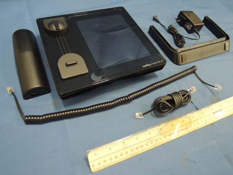
Click to zoom
Application Details
- Equipment Class
- DTS - Digital Transmission System
- Date of Grant
- Dec 22, 2014
- Application Purpose
- Original Equipment
- Date of Application
- Dec 22, 2014
- Equipment Note
- Corded Telephone with TAM, DECT6.0 and WiFi
- Frequency Range
- 2412.00000000 - 2462.00000000
- Company
- HP Inc.
- Country
- United States
Documents & Files
Document Text
Text extracted from the exhibit documents filed with the FCC. Open a document above to read the original.
Users Manual
HELLO! Let’s get started Easy, worry-free and dependable, your Clarity Ensemble is much more than just a telephone. It’s your communications center in a familiar shape that can help bring your family and friends closer to you with the photos and videos they share. And, a touchscreen that makes it easy to keep in touch. Your Ensemble is nearly ready to go right out of the box. The stand snaps into two slots on the back. Use the lower slots to hold the phone more upright; the upper slots hold it a little more horizontal. The power cord and the telephone cord on the back unwind with a tug. Plug the power cord into any wall socket or extension cord, and you’re ready to proceed. We’re right here! If something doesn’t make sense or you get in a jam, call us toll-free: 1-866-525-2748 2 The stand snaps into either of two pairs of slots on the back of the Ensemble. 3 Need help? Call us! 1-866-525-2748 4 Important safety instructions Power connection • Use only the power source marked on the product. • Do not overload power outlets and extension cords. This can result in the risk of fire or electric shock. • Completely insert the AC adapter/power plug into the power outlet. Failure to do so may cause electric shock and/or excessive heat resulting in a fire. • Regularly remove any dust, etc. from the AC adapter/ power plug by pulling it from the power outlet, then wiping with a dry cloth. Accumulated dust may cause an insulation defect from moisture, etc. resulting in a fire. • Unplug the product from power outlets if it emits smoke, an abnormal smell, or makes an unusual noise. These conditions can cause fire or electric shock. Confirm that smoke has stopped emitting and contact Clarity Customer Service at 800-426-3738. • Unplug from power outlets and never touch the inside of the product if its casing has been broken open. • Never touch the plug with wet hands. Danger of electric shock exists. Installation • To prevent the risk of fire or electrical shock, do not expose the product to rain or any type of moisture. • Do not place or use this product near automatically controlled devices such as automatic doors and fire alarms. Radio waves emitted from this product may cause To prevent severe injury and loss of life/property, read this section carefully before using the product to ensure proper and safe operation of your product. Save these instructions such devices to malfunction resulting in an accident. • Do not allow the AC adapter or telephone line cord to be excessively pulled, bent or placed under heavy objects. Operating safeguards • Unplug the product from power outlets before cleaning. Do not use liquid or aerosol cleaners. • Do not disassemble the product. • Do not spill liquids (detergents, cleansers, etc.) onto the telephone line cord plug, or allow it to become wet at all. This may cause a fire. If the telephone line cord plug becomes wet, immediately pull it from the telephone wall jack, and do not use. Medical • Consult the manufacturer of any personal medical devices, such as pacemakers or hearing aids, to determine if they are adequately shielded from external RF (radio frequency) energy. Do not disassemble the product. • Do not use the product in health care facilities if any regulations posted in the area instruct you not to do so. Hospitals or health care facilities may be using equipment that could be sensitive to external RF energy. Installation and Location • Never install telephone wiring during an electrical storm. • Never install telephone line jacks in wet locations unless the jack is specifically designed for wet locations. 5 Save these instructions 6 • Never touch uninsulated telephone wires or terminals unless the telephone line has been disconnected at the network interface. • Use caution when installing or modifying telephone lines. • The AC adapter is used as the main disconnect device. Ensure that the AC outlet is installed near the product and is easily accessible. • This product is unable to make calls when there is a power failure. • When using your product, basic safety precautions should always be followed to reduce the risk of fire, electric shock, and injury to persons, including the following: - Do not use this product near water, for example, near a bathtub, washbowl, kitchen sink, or laundry tub, in a wet basement or near a swimming pool. - Avoid using a telephone (other than a cordless type) during an electrical storm. There may be a remote risk of electric shock from lightning. - Do not use the telephone to report a gas leak in the vicinity of the leak. - Use only the power cord provided with your Ensemble and indicated in this manual. Environment • Keep the product away from electrical noise generating devices, such as fluorescent lamps and motors. • The product should be kept free from excessive smoke, dust, high temperature, and vibration. • The product should not be exposed to direct sunlight. For Best Performance Save these instructions 7 • Do not place heavy objects on top of the product. • When you leave the product unused for along period of time, unplug the product from the power outlet. • The product should be kept away from heat sources such as heaters, kitchen stoves, etc. It should not be placed in rooms where the temperature is less than 0 °C (32 °F) or greater than 40 °C (104 °F). Damp basements should also be avoided. • Operating the product near electrical appliances may cause interference. Move away from the electrical appliances. Routine care • Wipe the outer surface of the product with a soft, moist cloth. • Do not use benzene, thinner, or any abrasive powder to clean this product. Notice for product disposal, transfer, or return The Ensemble phone can store sensitive private information about you, so when it’s time to dispose of it, transfer it, or return it, you’ll want to reset it to erase that personal data. Contact your Ensemble’s Manager (see page 8) or call Clarity Customer Service toll-free at 1-866-525-2748 for assistance. …
Text truncated - open the document above for the full version.
External Photos
INTERTEK TESTING SERVICES External Photos FCC ID: AL8ENSEMBLE IC: 1186C-ENSEMBLE External photos - 1 of 2 Job Number HK14090632 Job Number HK14090632 INTERTEK TESTING SERVICES External Photos FCC ID: AL8ENSEMBLE IC: 1186C-ENSEMBLE External photos - 2 of 2
ID Label/Location Info
70255 Intertek CM Ensemble Clarity 65mm 33mm 800.426.3738 www.clarityproducts.com This device complies with Part 15 of the FCC rules. Operation is subject to the following two conditions: (1) This device may not cause harmful interference; and (2) This device must accept any interference received, including interference that may cause undesired operation. Privacy of communications may not be ensured when using this phone. M. Code: Model: Ensemble 12V 1.5A Complies with 47CFR Part 68 Technical Requirements FCC Reg. No.: US: AL8TE00BENSEMBLE FCC ID: AL8ENSEMBLE IC:1186C-ENSEMBLE IC REN:0.0 Ringer Equivalence: 0.0B US0C Jack: RJ11C BC 00B 0.0 0.0B RJ11C US: PRODUCT NAMEITEM PREPARED BY REVISION FORMAT DATE Ensemble ClaProduct Label B. Matney 10/14/14Rev A ARTWORK 00B 0.0B 0.0 RJ11C US: ENSEMBLE 58013000001FFFFF Ensemble Rev. 0 12/19/2014
Internal Photos
INTERTEK TESTING SERVICES Internal photos FCC ID: AL8ENSEMBLE IC: 1186C-ENSEMBLE internal photos - 1 of 11 Base Unit assembly (view 1) Base Unit assembly (view 2) INTERTEK TESTING SERVICES Internal photos FCC ID: AL8ENSEMBLE IC: 1186C-ENSEMBLE internal photos - 2 of 11 Base Unit assembly (view 3) Base Unit Main PCB comp side (View 1) INTERTEK TESTING SERVICES Internal photos FCC ID: AL8ENSEMBLE IC: 1186C-ENSEMBLE internal photos - 3 of 11 Bas e Unit Main PCB comp side (View 2) Base Unit Main PCB solder side INTERTEK TESTING SERVICES Internal photos FCC ID: AL8ENSEMBLE IC: 1186C-ENSEMBLE internal photos - 4 of 11 Base Unit AM3354BZCZ100 PCB comp side Base Unit AM3354BZCZ100 PCB solder side INTERTEK TESTING SERVICES Internal photos FCC ID: AL8ENSEMBLE IC: 1186C-ENSEMBLE internal photos - 5 of 11 Base Unit WiFi Module comp side Base Unit WiFi Module solder side INTERTEK TESTING SERVICES Internal photos FCC ID: AL8ENSEMBLE IC: 1186C-ENSEMBLE internal photos - 6 of 11 Bas e Unit Switch PCB comp side Base Unit Switch PCB solder side INTERTEK TESTING SERVICES Internal photos FCC ID: AL8ENSEMBLE IC: 1186C-ENSEMBLE internal photos - 7 of 11 Base Unit Hookswitch PCB comp side Base Unit Hookswitch PCB solder side INTERTEK TESTING SERVICES Internal photos FCC ID: AL8ENSEMBLE IC: 1186C-ENSEMBLE internal photos - 8 of 11 Base Unit modular jack PCB comp side Base Unit modular jack PCB solder side INTERTEK TESTING SERVICES Internal photos FCC ID: AL8ENSEMBLE IC: 1186C-ENSEMBLE internal photos - 9 of 11 Base Unit Reset PCB comp side Base Unit Reset PCB solder side INTERTEK TESTING SERVICES Internal photos FCC ID: AL8ENSEMBLE IC: 1186C-ENSEMBLE internal photos - 10 of 11 Base Unit – DECT Antenna Base Unit – WiFi Antenna INTERTEK TESTING SERVICES Internal photos FCC ID: AL8ENSEMBLE IC: 1186C-ENSEMBLE internal photos - 11 of 11 Base Unit Oscillator comp side Base Unit Oscillator solder side
RF Exposure Info
INTERTEK TESTING SERVICES FCC ID: AL8ENSEMBLE RF exposure - 1 of 2 For Maximum Permissible Exposure (MPE) evaluation of the base unit, the maximum power density at 20 cm from this mobile transmitter shall be less than the General Population / Uncontrolled MPE limit in OET Bulletin 65 and meet the requirement listed in KDB447498. For the 1.9GHz DECT Transmission of tested model: ENSEMBLE, the measured powers among all the measured channels were within its production tolerance: +15.5 dBm (Minimum) and +20.5 dBm (Maximum). The antenna gain of ENSEMBLE is 0 dBi = 1.00 (num gain) and it s maximum source-based time-averaging duty factor is 20.8% (5/24 x100%). From these data and its operating configuration – Mobile device, the exposed power density at a distance (R) of 20cm from the center of radiation of the antenna can be calculated according to OET Bulletin 65 as follow: The Conducted Power = 20.5 dBm = 112.2 mW The Conducted Power source-based time-averaging output power = (112.2 * 0.208) mW = 23.34 mW The power density at 20cm = 23.34 *1.00/ 4R 2 = 0.0047 mW cm -2 For the 2.4GHz WiFi Transmission of tested model: ENSEMBLE, the measured powers among all the measured channels were within its production tolerance: 14 dBm (Minimum) and 25 dBm (Maximum). The antenna gain of ENSEMBLE is 0 dBi = 1.00 (num gain) and its maxi mum source-based time-averaging duty factor is 100.0% (1 x100%). From these data and its operating configuration – Mobile device, the exposed power density at a distance (R) of 20cm from the center of radiation of the antenna can be calculated according to OET Bulletin 65 a s follow: The Conducted Power = 25 dBm = 316.2 mW The Conducted Power source-based time-averaging output power = (316.2 * 1.000) mW = 316.23 mW The power density at 20cm = 316.23 *1.00/ 4R 2 = 0.0629 mW cm -2 INTERTEK TESTING SERVICES FCC ID: AL8ENSEMBLE RF exposure - 2 of 2 Per KDB 447498 D01 v05, simultaneous transmission MPE test exclusion applies when the sum of the MPE ratios for all simultaneous transmitting antennas incorporated in a host device, based on calculated or measured field strengths or power density, is ≤ 1.0. The MPE ratio for DECT Transmission can be calculated as follow: = The power density at 20cm / MPE limit = 0.0047 mW c m -2 / 1.0 mW cm -2 = 0.0047 The MPE ratio for WiFi Transmission can be calculated as follow: = The power density at 20cm / MPE limit = 0.0629 mW c m -2 / 1.0 mW cm -2 = 0.0629 The sum of the MPE ratios for all simultaneous transmitting antennas = 0.0047 + 0.0629 = 0.0676 As the sum of MPE ratios for all simultaneous transmitting antennas is ≤ 1.0, simultaneous transmission MPE test exclusion will be applied. Conclusion In frequency range of 1,500 - 100,000MHz, the MPE limit is 1.0 mWcm -2 for general population and uncontrolled exposure. As simultaneous transmission MPE test exclusion is applied and the measured power density at 20cm from all the standalone transmissions is lower than the MPE limi t, the compliance to the MPE limit can be ensured by indicating the minimum 20cm separation between the transmitter's radiating structures and body of the user or near by persons. The following RF exposure statement is proposed to be included in the user manual: “ FCC RF Radiation Exposure Statement Caution: To maintain compliance with the FCC’s RF exposure guidelines, place the base unit at least 20cm from nearby persons.”
Test Report
- Intertek’s standard Terms and Conditions can be obtained at our website: http://www.intertek.com/terms/. - The test report only allows to be revised within the retention period unless further standard or the requirement was noticed. - This report is for the exclusive use of Intertek's Client and is provided pursuant to the agreement between Intertek and its Client. Intertek's responsibility and liability are limited to the terms and conditions of the agreement. Intertek assumes no liability to any party, other than to the Client in accordance with the agreement, for any loss, expense or damage occasioned by the use of this report. Only the Client is authorized to permit copying or distribution of this report and then only in its entirety. Any use of the Intertek name or one of its marks for the sale or advertisement of the tested material, product or service must first be approved in writing by Intertek. The observations and test results in this report are relevant only to the sample tested. This report by itself does not imply that the material, product, or service is or has ever been under an Intertek certification program. Intertek Testing Services Hong Kong Ltd. 2/F., Garment Centre, 576 Castle Peak Road, Kowloon, Hong Kong. Tel: (852) 2173 8888 Fax: (852) 2785 5487 Website: www.hk.intertek-etlsemko.com TEST REPORT Report Number: 14090632HKG-002 Application for Original Grant of 47 CFR Part 15 Certification Single New of RSS-210 Issue 8 Equipment Certification (WiFi Base Unit) FCC ID: AL8ENSEMBLE IC: 1186C-ENSEMBLE Test Engineer: Approved by: Signed on File Leung Chiu Kuen, Stanley Nip Ming Fung, Melvin Engineer Assistant Manager December 12, 2014 INTERTEK TESTING SERVICES Test Report Number: 14090632HKG-002 Page 1 of 47 FCC ID: AL8SENSEMBLE IC: 1186A-ENSEMBLE GENERAL INFORMATION FCC Applicant Name: Plantronics, Inc. FCC Applicant Address: 345 Encinal Street, Santa Cruz, CA 95060, USA IC Applicant Name: Clarity, A Division of Plantronics, Inc. IC Applicant Address: 6131 Preservation Drive, Chattanooga, TN 37416 USA FCC Specification Standard: FCC Part 15, October 1, 2012 Edition FCC ID: AL8ENSEMBLE FCC Model(s): ENSEMBLE IC Specification Standard: RSS-210 Issue 8, December 2010 RSS-Gen Issue 3, December 2010 IC: 1186C-ENSEMBLE IC Model(s): ENSEMBLE Type of EUT: Unlicensed Personal Communications Service Devices Description of EUT: 1.9GHz Digital Modulation DECT with Caller-ID, Speakerphone, Digital Answering Machine, color touch screen, internet and WiFi features - Base Unit Serial Number: N/A Sample Receipt Date: September 15, 2014 Date of Test: August 22, 2014 to September 27,2014 Report Date: December 12, 2014 Environmental Conditions: Temperature: +10 to 40°C Humidity: 10 to 90% INTERTEK TESTING SERVICES Test Report Number: 14090632HKG-002 Page 2 of 47 FCC ID: AL8SENSEMBLE IC: 1186A-ENSEMBLE Table of Contents 1.0 Summary of Test Results........................................................................................ 4 1.1 Statement of Compliance ........................................................................................ 4 2.0 General Description................................................................................................. 6 2.1 Product Description ................................................................................................. 6 2.2 Test Methodology.................................................................................................... 7 2.3 Test Facility............................................................................................................. 7 3.0 System Test Configuration...................................................................................... 9 3.1 Justification ............................................................................................................. 9 3.2 EUT Exercising Software....................................................................................... 10 3.3 Details of EUT and Description of Accessories...................................................... 11 3.4 Measurement Uncertainty ..................................................................................... 11 4.0 Test Results............................................................................................................ 13 4.1 Maximum Conducted Output Power at Antenna Terminals .................................... 13 4.2 Minimum 6dB RF Bandwidth ................................................................................. 15 4.3 Maximum Power Spectral Density ......................................................................... 20 4.4 Out of Band Conducted Emissions ........................................................................ 25 4.5 Field Strength Calculation...................................................................................... 32 4.6 Transmitter Radiated Emissions in Restricted Bands and Spurious Emissions....... 33 4.6.1 Radiated Emission Configuration Photograph ..................................................... 34 4.6.2 Radiated Emission Data ..................................................................................... 34 4.6.3 Transmitter Duty Cycle Calculation ..................................................................... 42 4.7 AC Power Line Conducted Emission ..................................................................... 43 4.7.1 AC Power Line Conducted Emission Configuration Photograph.......................... 43 4.7.2 AC Power Line Conducted Emission Data .......................................................... 43 5.0 Equipment List....................................................................................................... 47 INTERTEK TESTING SERVICES Test Report Number: 14090632HKG-002 Page 3 of 47 FCC ID: AL8SENSEMBLE IC: 1186A-ENSEMBLE EXHIBIT 1 SUMMARY OF TEST RESULTS & STATEMENT OF COMPLIANCE INTERTEK TESTING SERVICES Test Report Number: 14090632HKG-002 Page 4 of 47 FCC ID: AL8…
Text truncated - open the document above for the full version.
Test Setup Photos
INTERTEK TESTING SERVICES The Worst Case Configuration Photographs - Mode: Transmission FCC ID: AL8ENSEMBLE IC: 1186C-ENSEMBLE config photos (radiated emission - base unit) - 1 of 1 Radiated Emission - Base Unit Front View Rear View INTERTEK TESTING SERVICES The Worst Case Configuration Photographs - Mode: Talk (DECT+WiFi) FCC ID: AL8ENSEMBLE IC: 1186C-ENSEMBLE config photos (conducted emission) - 1 of 2 Conducted Emission Front View Right Side View INTERTEK TESTING SERVICES The Worst Case Configuration Photographs - Mode: Talk (DECT+WiFi) FCC ID: AL8ENSEMBLE IC: 1186C-ENSEMBLE config photos (conducted emission) - 2 of 2 Conducted Emission Left Side View
Contact Information
Applicant
Richard Tarsio(US/CAN TRSE Worldwide Technical Regulations)
Technical Contact
Intertek Testing Services Hong Kong Ltd.Melvin Nip
[email protected](852) 2173 8535
2/F., Garment Centre, · Kowloon · Hong Kong
Non-Technical Contact
Intertek Testing Services Hong Kong Ltd.Melvin Nip
[email protected](852) 2173 8535
Test Firm
Intertek Testing Services Hong Kong Ltd.Billy Chow
Technical Specifications
| # | Rule Parts | Frequency Range | Power Output |
|---|---|---|---|
| 1 | 15C | 2.41 GHz - 2.46 GHz | 200.00 mW |
Other Applications from HP Inc.
AL8-PWPTF620P
Feb 03, 2026Wireless Charge Stand
Equipment Class
DCD - Part 15 Low Power Transmitter Below 1705 kHzAL8-PBF620F
Jan 23, 2026Bluetooth Headset
Equipment Class
DTS - Digital Transmission SystemAL8-PBVOYX2
Jun 20, 2024Bluetooth Base
Equipment Class
DTS - Digital Transmission System
AL8-VF2R
Mar 07, 2024Wireless Bluetooth Earphones
Equipment Class
DTS - Digital Transmission System
AL8-CBVS1
Oct 16, 2023Wireless Charge Stand
Equipment Class
DXX - Part 15 Low Power Communication Device Transmitter