AL8XLC341.9GHz CORDLESS PHONE
HP Inc.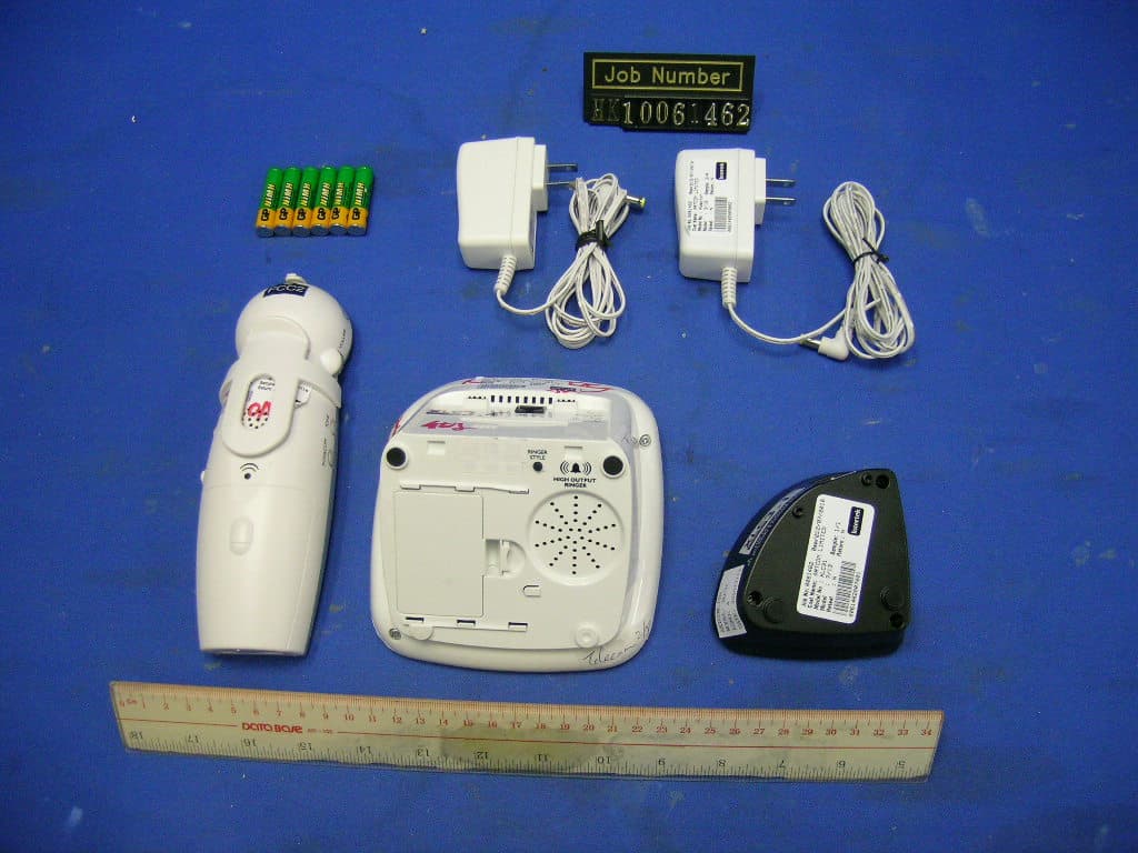
Click to zoom
Application Details
- Equipment Class
- PUE - Part 15 Unlicensed PCS portable Tx held to ear
- Date of Grant
- Oct 18, 2010
- Application Purpose
- Original Equipment
- Date of Application
- Oct 12, 2010
- Equipment Note
- 1.9GHz CORDLESS PHONE
- Frequency Range
- 1921.53600000 - 1928.44800000
- Company
- HP Inc.
- Country
- United States
Documents & Files
Document Text
Text extracted from the exhibit documents filed with the FCC. Open a document above to read the original.
Users Manual
E S P A ~ N O L E N G L I S H F R A N Ç A I S User Guide IN USE/ CHARGE POWER VOLUME FIND SILENT MENU TALK FLASH EXIT MUTE BACK RD/P ! BOOST PRINTED IN CHINA Clarity, a Division of Plantronics, Inc. 4289 Bonny Oaks Drive, Chattanooga, TN 37406 Tel: 800-426-3738 Fax: 800-325-8871 E-mail: [email protected] Website: www.clarityproducts.com ©2010 Clarity, a Division of Plantronics, Inc. All rights reserved. Clarity, Clarity Professional, XLC3.4, Digital Clarity Power and the amplified figure are trademarks or registered trademarks of Plantronics, Inc. Rev. A (09-10) Extra Loud Cordless Speakerphone with Caller ID E N G L I S H TABLE OF CONTENTS XLC3.4 IMPORTANT SAFETY INSTRUCTIONS 2 CONTENTS & PARTS CHECKLIST 5 INSTALLATION 6 WALL MOUNTING YOUR XLC3.4 8 BASE - Quick Reference Guide 10 HANDSET - Quick Reference Guide 11 BATTERY INFORMATION 14 PLACING & ANSWERING CALLS 15 VOLUME & TONE ADJUSTMENTS 16 CALLER ID FUNCTION 16 PHONEBOOK 17 SCREEN DETAILS 17 TELEPHONE MENU 19 HANDSET REGISTRATION 28 TROUBLESHOOTING 29 TECHNICAL SPECIFICATIONS 32 REGULATORY COMPLIANCE 33 WARRANTY INFORMATION 36 23 E N G L I S H SAVE THESE INSTRUCTIONS SAVE THESE INSTRUCTIONS When using your telephone equipment, basic safety precautions should always be followed to reduce the risk of fire, electric shock and injury to persons, including the following: 1. Read and understand all instructions. 2. Follow all warnings and instructions marked on the telephone. 3. Avoid contact with liquids. Do not locate base unit or handset near water, for example, near a bathtub, wash basin, sink or laundry tub, in a wet basement or near a swimming pool. 4. Avoid using a telephone (other than a cordless type) during a storm. There may be a remote risk of electrical shock from lightning. 5. Do not use the telephone to report a gas leak in the vicinity of the leak. 6. Unplug this telephone from the wall outlets before cleaning. Do not use liquid cleaners or aerosol cleaners on the telephone. Use a damp cloth for cleaning. 7. Place this telephone on a stable surface. Serious damage and/or injury may result if the telephone falls. 8. Do not cover the slots and openings on this telephone. This telephone should never be placed near or over a radiator or heat register. This telephone should not be placed in a built-in installation unless proper ventilation is provided. 9. Operate this telephone using the electrical voltage as stated on the base unit or the owner’s manual. If you are not sure of the voltage in your home, consult your dealer or local power company. 10. Do not allow anything to rest on the power cord or locate this product in an area where the power cord is likely to be damaged by furniture or foot traffic. 11. Do not overload wall outlets or extension cords as this can increase the risk of fire or electrical shock. 12. Never push any objects through the slots in the telephone. They can touch dangerous voltage points or short out parts that could result in a risk of fire or electrical shock. Never spill liquid of any kind on the telephone. 13. To reduce the risk of electrical shock, do not take this phone apart. Opening or removing covers may expose you to dangerous voltages or other risks. Incorrect reassembly can cause electric shock when the appliance is subsequently used. 14. Unplug this product from the wall outlet and refer servicing to the manufacturer under the following conditions: when the power supply cord or plug is frayed or damaged; if liquid has been spilled into the product; if the telephone has been exposed to rain or water; if the telephone has been dropped or the case has been damaged; if the telephone exhibits a distinct change in performance; if the telephone does not operate normally by following the operating instructions. Adjust only those controls that are covered by the operating instructions. Improper adjustment may require extensive work by a qualified technician to restore the telephone to normal operation if the telephone does not operate normally by following the operating instructions. 15. Never install telephone wiring during a lightning storm. 16. Never install telephone jacks in wet locations unless the jack is specifically designed for wet locations. 17. Never touch uninsulated telephone wires or terminals unless the telephone line has been disconnected at the network interface. 18. Use caution when installing or modifying telephone lines. 19. This product should be operated only from the type of power source indicated on the marking label. If you are not sure of the type of power supply to your home, consult your local power company. 20. Do not attempt to open the AC adapter. There are potentially dangerous voltages inside, and there are no serviceable parts. 21. Discontinue use of product and contact Clarity if the product overheats, has a damaged cord or plug, if the product has been dropped or damaged or if the product has come into contact with liquids. 22. Use only the AC adapter provided with this product or a replacement AC adapter provided by Clarity. 23. This phone amplifies sound to loud volumes. To prevent hearing damage, all users of the phone should be informed of the high volume capability of the phone and children should only use the phone when supervised by an adult. 24. Exposure to high volume sound levels or excessive sound pressure may cause temporary or permanent damage to your hearing. Although there is no single volume setting that is appropriate for everyone, you should always use your telephone with the volume set at moderate levels and avoid prolonged exposure to high volume sound levels. The louder the volume, the less time is required before your hearing could be IMPORTANT SAFETY INSTRUCTIONS XLC3.4 IMPORTANT SAFETY INSTRUCTIONS XLC3.4 45 E N G L I S H TONE INTERCOM Base Handset Belt clip AC power adapter Long Phone cord User guide Short Phone cord SAVE THESE INSTRUCTIONS affected. If you experience hearing discomfort, you should have your hearing checked by…
Text truncated - open the document above for the full version.
Users Manual
2223 E N G L I S H MENU - PHONEBOOK XLC3.4 • To delete the saved record, press DOWN twice to advance the row that reads “Del Number” to the top of the screen. Press MENU to select this option. The screen displays “Delete?” Press MENU to delete (screen displays “OK” and you hear five beeps), or MUTE / BACK to return to previous screen. • To delete all records, press DOWN three times, to advance the row that reads “Delete All” to the top of the screen. Press MENU to select this option. The screen displays “Delete All?” Press MENU to delete all records (screen displays “OK” and you hear five beeps), or MUTE / BACK to return to previous screen. Del Number Delete All ------------ Delete? OK Add Number Delete All ------------ MENU - RINGER SETUP XLC3.4 Phonebook Caller List Ring Setup In standby mode, press MENU. Press DOWN arrow twice, to advance the row that reads “Ring Setup” to the top of the screen. Press MENU to enter the ringer setup. You will see the available options for your ringer. From here, choose one of the paths described below: Visual Ringer Boost Setup Ring Setup Ringer Tone Keypad Tone Ringer Vol • Press MENU to adjust the ringer volume. Use UP or DOWN to reach the desired level of ring loudness. When finished, press MENU to save your setting. Screen will display “OK” and you will hear five beeps. • To adjust the ringer tone, press DOWN to advance the row that reads “Ringer Tone” to the top of the screen. Press MENU to select this option. Use UP or DOWN to scroll through the available ring tones. Press MENU to save the setting you selected. Screen will display “OK” and you will hear five beeps. • To turn the keypad tones on or off, press DOWN twice to advance the row that reads “Keypad Tone” to the top of the screen. Press MENU to select this option. Use UP or DOWN to make your selection - indicated by the cursor on the left of the screen. Press MENU to save your selection. Screen will display “OK” and you will hear five beeps. MENU - RINGER SETUP XLC3.4 Lo |||||||| Hi Ringer Vol Ring Tone 2 Ring Tone 3 Ring Tone 1 Keypad Tone Ringer Vol ------------- Keypad Tone On Off OK OK OK 2425 E N G L I S H MENU - VISUAL RING (Handset) XLC3.4 Phonebook Caller List Ring Setup In standby mode, press MENU. Press DOWN arrow three times, to advance the row that reads “Visual Ring” to the top of the screen. Press MENU to enter the handset visual ringer On / Off setup. Use UP or DOWN to make your selection - indicated by the cursor on the left of the screen. Press MENU to save your selection. Screen will display “OK” and you will hear five beeps. NOTE: This option refers to the handset visual ringer only. MENU - AUTO BOOST In standby mode, press MENU. Press DOWN arrow four times, to advance the row that reads “Auto Boost” to the top of the screen. Press MENU to enter the Auto Boost On / Off setup. Use UP or DOWN to make your selection - indicated by the cursor on the left of the screen. Press MENU to save your selection. Screen will display “OK” and you will hear five beeps. Phonebook Caller List Ring Setup XLC3.4 Phone Setup Auto Boost Date & Time Off Auto Boost On Phone Setup Auto Boost Visual Ring Visual Ring On Off MENU - PHONE SETUP XLC3.4 In standby mode, press MENU. Press DOWN arrow five times, to advance the row that reads “Phone Setup” to the top of the screen. Press MENU to enter the Phone Setup submenu. The Phone Setup submenu allows you to adjust the following features: • Register • Auto Talk (On / Off, default: Off) • Voice Assist (Voice Asst; On / Off, default: On) • Any Key Answer (On / Off; default: Off) • Language (English/French/Spanish, default: English) • Dial Mode (Tone / Pulse, default: Tone) • Contrast (1-5, default: 3) From here, choose one of the paths described below: • Register Press MENU to access this function. See details on page 28. • Auto Talk Press DOWN once to advance the row reading “Auto Talk” to the top of the screen. Press MENU to enter this option. Use UP or DOWN to make your selection - indicated by the cursor on the left of the screen. Press MENU to save your selection. Screen will display “OK” and you will hear five beeps. • Voice Assist Press DOWN twice to advance the row reading “Voice Asst” to the top of the screen. This option activates the audio numbers - both for the phone numbers dialed, as well as the incoming phone numbers (with optional CID service from your local phone service provider.) Phonebook Caller List Ring Setup Phone Setup ----------- Date & Time Register Voice Asst Auto Talk Auto Talk Any Key Ans Voice Asst Auto Talk On Off VoiJe (ZZ[ 3ang\age (ny Key (nZ 2627 E N G L I S H Dial Mode ---------- Contrast Dial Mode Pulse Tone Press MENU to enter this option. Use UP or DOWN to make your selection - indicated by the cursor on the left of the screen. Press MENU to save your selection. Screen will display “OK” and you will hear five beeps. • Any Key Answer Press DOWN three times to advance the row reading “Any Key Ans” to the top of the screen. This feature allows you to answer the call by pressing any numeric key on the handset, rather than pressing TALK and Speakerphone. Press MENU to enter this option. Use UP or DOWN to make your selection - indicated by the cursor on the left of the screen. Press MENU to save your selection. Screen will display “OK” and you will hear five beeps. • Language Press DOWN five times to advance the row reading “Language” to the top of the screen. Press MENU to enter this option. Use UP or DOWN to make your selection - indicated by the cursor on the left of the screen. Press MENU to save your selection. Screen will display “OK” and you will hear five beeps. • Dial Mode Press DOWN six times to advance the row reading “Dial Mode” to the top of the screen. Press MENU to enter this option. Use UP or DOWN to make your selection - indicated by the cursor on the left of the screen. Press MENU to save your selection. Screen will display “OK” and you will hear five beeps. MENU - PHONE SETUP XLC3.4 Voice Asst On Off…
Text truncated - open the document above for the full version.
Cover Letter(s)
Worldwide Headquarters 345 Encinal Street Santa Cruz, CA 95060 Declarations FCC ID: AL8XLC34 Date: August 05, 2010 To whom it may concern, _________ Name: Peter Clark Title:Compliance Manager I, the undersigned, hereby declare that 1. The device does not use the provisions of 47CFR 15.323 (c) (6), random waiting mechanism is not used in this system. 2. The provisions of 47CFR 15.323 (c) (10) and 47CFR 15.323 (c) (11) are not used to extend the range of spectrum occupied over space or time for the purpose of denying fair access to spectrum to other devices. 3. Only the handset will act as the initiat ing device, which will initiate the establishment of the duplex connection. 4 . The device complies with the provisions of 47CFR 15.319(f). The device shall automatically discontinue transmission in case of either absence of information to transmit or operational failure. These provisions are not intended to preclude transmission of control and signaling information or use of repetitive codes used by certain digital technologies to complete frame or burst intervals. The following table explains the reacti on of device in case of either absence of information to transmit or operational failure after a connection of its companion device is established. a BfonoitcaeRsecnatsmucriCse UnitReactio n of Handset ANANecivednoinapmocffo-hctiwS1 ANBecivednoinapmocybkooHnO2 ANANecivedffo-hctiwS3 CANedisecivednokooHnO4 CAecivedmorfrewopevomeR5 ABecivednoinapmocmorfrewopevomeR6 A–Connectio n is termin ated and, transmissi on ceases. B–Connection is terminated but device transmits control or signaling information. C–Connection is terminated but companion device transmits control or signaling information. NA–Not applicable If you have questions or need furth er information, please contact the undersigned. Regards,
Cover Letter(s)
Worldwide Headquarters 345 Encinal Street Santa Cruz CA 95060, Appendix B1 Letter of Agency for FCC Certification Aug 05 2010., To whom it may concern, Letter of Agency Peter Clark Compliance Manager I, an officer ofPlantronics Inc. do hereby authorize Intertek Testing Services (Mr.Ken Sit/ Mr. Tommy Leung/Mr. Melvin Nip) to act on our behalf in front of the Federal Communications Commission with respect to all matters relating to certification of equipment under Part 15 and/or Part 95 of the FCC Rules until further notice. I further certify that no party (as defined in §1.2002(b) of CFR 47, 2004) to this application, including myself, is subject to a denial of federal benefits, that includes FCC benefits, pursuant to Section 5301 of the Anti-DrugAbuse Act of 1988, 21 U.S.C., 862. Regards,
Cover Letter(s)
Worldwide Headquarters 345 Encinal Street Santa Cruz, CA 95060 Aug. 05, 2010 To whom it may concern, Peter Clark Compliance Manager Request for Permanent Confidentiality Under FCC Part 15 Certification FCC ID:AL8XLC34 Request is hereby submitted by Plantronics Inc. to withhold permanently from public review certain portions of the application for equipment certification for the referenced FCC identifiers. This request for confidentiality is made pursuant to 47 CFR § 0.457(d) and 0.459 of the FCC Rules. In particular, the following sections of the application are to be kept permanently confidential and Plantronics Inc. reserves the right to discern which parties can obtain access to these information: •Schematics [AL8XLC34_circuit.pdf] •Detailed Block diagrams [AL8XLC34_block.pdf] •Detailed Operational/Functional Description [AL8XLC34_descri 1.pdf & AL8XLC34_descri 2.pdf] The rationale for request for confidentiality is as followings: This information represents intellec tual property of Plantronics Inc. and it is subject to competition. We have invested considerable time and materials in research and development to produce the referenced product. Disclosure of the permanently confidential portions of this application to competitors would not only give them significant competitive advantages in developing similar products, but would also disclose successful implementation of unpublished, leading edge technology developed by us. If you have questions or need further information, please contact the undersigned. Regards,
External Photos
INTERTEK TESTING SERVICES External Photos FCC ID: AL8XLC34 external photos - 1 of 3 INTERTEK TESTING SERVICES External Photos FCC ID: AL8XLC34 external photos - 2 of 3 INTERTEK TESTING SERVICES External Photos FCC ID: AL8XLC34 external photos - 3 of 3
ID Label/Location Info
XLC3.4Rev. 108/02/2010 AAA SIZE RECHARGEABLE AAA SIZE RECHARGEABLE AAA SIZE RECHARGEABLE 70255 Intertek CM XLC3.4 AL8XLC34 XLC34 AL8W400BXLC34 XLC34 070710 XLC3.4 ?????100001 Use 3-AAA Rechargeable Batteries Utilisez 3 piles rechargeable AAA WARNING: Disconnect phone cord before replacing batteries ATTENTION: Débrancher les lignes téléphoniques avant le remplacement des piles. Size: 46mm x 24mm 8.8mm Size: 27mm x 27mm XLC3.4Rev. 108/02/2010 XL 34 XL 3.4 34 L8 AAA SIZE RECHARGEABLE AAA SIZE RECHARGEABLE WHEN BOOST BUTTON IS LIT VOLUME MAYBE AT A HIGH LEVEL. TO PROTECT HEARING,LOWER VOLUME CONTROL TO MINIMUM. WARNING Braille Label Size: 22mm x 4.8mm
Internal Photos
INTERTEK TESTING SERVICES Internal photos FCC ID: AL8XLC34 internal photos - 1 of 10 Base Unit assembly Base Unit Main PCB comp side INTERTEK TESTING SERVICES Internal photos FCC ID: AL8XLC34 internal photos - 2 of 10 Base Unit Main PCB solder side (View 1) Base Unit Main PCB solder side (View 2) INTERTEK TESTING SERVICES Internal photos FCC ID: AL8XLC34 internal photos - 3 of 10 Base Unit Charging Board “1” PCB front side Base Unit Charging Board “1” PCB rear side INTERTEK TESTING SERVICES Internal photos FCC ID: AL8XLC34 internal photos - 4 of 10 Base Unit Charging Board “2” PCB front side Base Unit Charging Board “1” PCB rear side INTERTEK TESTING SERVICES Internal photos FCC ID: AL8XLC34 internal photos - 5 of 10 Base Unit Page Key front side Base Unit Page Key rear side INTERTEK TESTING SERVICES Internal photos FCC ID: AL8XLC34 internal photos - 6 of 10 Base Unit Oscillator PCB comp side INTERTEK TESTING SERVICES Internal photos FCC ID: AL8XLC34 internal photos - 7 of 10 Handset assembly Handset Main PCB comp side (View 1) INTERTEK TESTING SERVICES Internal photos FCC ID: AL8XLC34 internal photos - 8 of 10 Handset Main PCB comp side (View 2) Handset Main PCB display side (View 1) INTERTEK TESTING SERVICES Internal photos FCC ID: AL8XLC34 internal photos - 9 of 10 Handset Main PCB display side (View 2) Handset Main PCB display side (View 3) INTERTEK TESTING SERVICES Internal photos FCC ID: AL8XLC34 internal photos - 10 of 10 Handset Oscillator PCB comp side
RF Exposure Info
Report No.: TS10070113-EME Page 1 of 77 Specific Absorption Rate (SAR) Test Report for Plantronics Inc. on the 1.9GHz DECT 6.0 Cordless Phone Model Number: XLC3.4, XLC3.1 Test Report: TS10070113-EME Date of Report: Aug. 20, 2010 Date of test: Aug. 20, 2010 Review Date: Aug. 24, 2010 Total No of Pages Contained in this Report: 77 The test report was prepared by: Sign on File Shirla Hsiao / Officer These measurements were taken by: Sign on File Fred Yu / Engineer The test report was reviewed by: Name Rex Liao Title Engineer All services undertaken are subject to the following general policy: Reports are submitted for exclusive use of the client to whom they are addressed. Their significance is subject to the adequacy and representative character of the samples and to the comprehensiveness of the tests, examinations or surveys made. This report shall not be reproduced except in full, without written consent of Intertek Testing Services, Taiwan Ltd. 0597 Report No.: TS10070113-EME Page 2 of 77 Table of Contents 1.0 General information...................................................................................... 3 2.0 SAR Evaluation ............................................................................................ 7 3.0 Test Instruments and Tissue Liquids.......................................................... 20 4.0 Measurement Uncertainty .......................................................................... 25 5.0 Test Results................................................................................................ 27 6.0 E-Field Probe and 1900 Dipole Antenna Calibration .................................. 28 7.0 WARNING LABEL INFORMATION - USA.................................................. 28 8.0 REFERENCES........................................................................................... 28 9.0 DOCUMENT HISTORY .............................................................................. 29 APPENDIX A - SAR Evaluation Data ............................................................... 30 APPENDIX B - Photographs ............................................................................ 43 APPENDIX C - E-Field Probe and 1900MHz Dipole Antenna Calibration Data 48 Report No.: TS10070113-EME Page 3 of 77 1.0 General information The XLC3.4 handset supplied for Specific Absorption Rate (SAR) testing is a 1.9GHz DECT 6.0 Cordless Phone device. The device was tested at the facility of Intertek Testing Services in Hsinchu, Taiwan. The maximum output power declared by Plantronics Inc. EUT model #XLC3.4 was evaluated in accordance with the requirements for compliance testing defined in FCC OET Bulletin 65 Supplement C (Edition 01-01), RSS-102 and meet the SAR requirement. For the evaluation, the dosimetric assessment system INDEXSAR SARA2 was used. The phantom employed was the head Specific Anthropomorphic Mannequin (SAM) phantom and the box phantom of 2mm thick in one wall. The total uncertainty for the evaluation of the spatial peak SAR values averaged over a cube of 1g tissue mass had been assessed for this system to be ±20.6%. SAR testing was performed at both the left and right ear of the phantom at the two-handset positions stated in the specification. 2mm thick box phantom for body configuration was also evaluated. Testing was performed at the middle frequency of 1900 band with a rechargeable battery and in Normal mode of operation. Any accessories supplied with XLC3.4 have also been tested. The client confirmed the model: XLC3.1 was a series model to model XLC3.4 (EUT), the differences are listed as below. Model Number Differences XLC3.4 1 Base + 1 Handset with LCD XLC3.1 1 XLC3.4 Handset with LCD + 1 charger In summary, the maximum spatial peak SAR value for the sample device averaged over 1g was found to be: Phantom Worst Case Position SAR 1g , W/kg Head Specific Anthropomorphic Mannequin (SAM) phantom EUT Left Tilt to the phantom 0.004 W/kg 2mm thick box phantom wall Separating the Box with belt-clip attached in rear position from EUT with neckloop 0.038 W/kg In conclusion, the tested Sample device was found to be in compliance with the requirements defined in OET Bulletin 65 Supplement C (Edition 01-01) and RSS-102 for head and body configurations. Report No.: TS10070113-EME Page 4 of 77 1.1 Client Information The 1.9GHz DECT 6.0 Cordless Phone has been tested at the request of: Applicant: Plantronics Inc. 345 Encinal Street, Santa Cruz, CA 95060, USA 1.2 Equipment under test (EUT) Product Descriptions: Equipment 1.9GHz DECT 6.0 Cordless Phone Trade Name Clarity Model No. XLC3.4 FCC ID AL8XLC34 S/N No. Not Labeled Category Portable RF Exposure Uncontrolled Environment Frequency Band 1921.536 -1928.448 MHz System / Power Level DECT EUT Antenna Description Type Integral ConfigurationFixed Dimensions 38 mm length Gain 0 dBi Location Embedded Use of product: 1.9GHz DECT 6.0 Cordless Phone Manufacturer: Artcom Limited Production is planned: [X] Yes, [ ] No EUT receive date: Jul. 19, 2010 EUT received condition: Good operating condition prototype EUT status: Normal mode Test start date: Aug. 20, 2010 Test end date: Aug. 20, 2010 Report No.: TS10070113-EME Page 5 of 77 1.3 Modifications required for compliance The EUT has no modifications during test. 1.4 System test configuration 1.4.1 System block diagram & Support equipment Support Equipment Item # Equipment Model No. S/N 1 Base unit XLC3.4 N/A 2 Head set M110 N/A 3 Neck loop CE30 N/A Report No.: TS10070113-EME Page 6 of 77 1.4.2 Test Position See the photographs as section 2.2 1.4.3 Test Condition During tests the worst-case data (max RF coupling) was determined with following conditions: Usage Operated in normal mode with Base unit which provided by client Distance between antenna axis at the joint and the liquid surface: Handset is touching and tilting the Head Phantom in right and left position, separating the Body Phantom with belt-clip in rear from EUT with headset or neckloop Simulating hum…
Text truncated - open the document above for the full version.
Test Report
INTERTEK TESTING SERVICES 26dB Emission Bandwidth Plots FCC ID: AL8XLC34 26bw - 1 of 3 A0 Base unit, Lowest channel, Traffic carrier Base unit, Highest channel, Traffic carrier INTERTEK TESTING SERVICES 26dB Emission Bandwidth Plots FCC ID: AL8XLC34 26bw - 2 of 3 A0 Base unit, Lowest channel, Dummy carrier Base unit, Highest channel, Dummy carrier INTERTEK TESTING SERVICES 26dB Emission Bandwidth Plots FCC ID: AL8XLC34 26bw - 3 of 3 A0 Handset unit, Lowest channel, Traffic carrier Handset unit, Highest channel, Traffic carrier
Test Report
Report no.: HK10061462-3 Talk Mode AC Mains Ctrl No.: N/A 150 kHz30 MHz 1 PK CLRWR 2 AV CLRWR SGL TDS 6DB dBμV dBμV AC RBW 9 kHz MT 1 s PREAMP OFFAtt 10 dB AUTO 1 MHz10 MHz 0 10 20 30 40 50 60 70 80 90 100 CF15MAV CF15MQP Date: 11.AUG.2010 17:39:33 Report no.: HK10061462-3 Talk Mode AC Mains Ctrl No.: N/A EDIT PEAK LIST (Final Measurement Results) Trace1: CF15MQP Trace2: CF15MAV Trace3: --- TRACE FREQUENCY LEVEL dBμV DELTA LIMIT dB 1 Quasi Peak 181.5 kHz 38.77 N gnd -25.64 1 Quasi Peak 402 kHz 40.01 N gnd -17.79 1 Quasi Peak 510 kHz 38.53 N gnd -17.46 2 CISPR Average546 kHz 28.27 L1 gnd -17.72 1 Quasi Peak 622.5 kHz 37.11 N gnd -18.88 1 Quasi Peak 883.5 kHz 38.79 L1 gnd -17.20 1 Quasi Peak 1.419 MHz 38.56 L1 gnd -17.43 1 Quasi Peak 1.626 MHz 39.18 L1 gnd -16.81 2 CISPR Average1.743 MHz 26.22 N gnd -19.77 2 CISPR Average2.328 MHz 23.73 N gnd -22.26 1 Quasi Peak 2.598 MHz 37.28 N gnd -18.71 2 CISPR Average3.9975 MHz 27.24 L1 gnd -18.75 1 Quasi Peak 4.002 MHz 40.43 L1 gnd -15.56 1 Quasi Peak 5.7165 MHz 54.74 N gnd -5.25 2 CISPR Average5.721 MHz 37.89 N gnd -12.10 1 Quasi Peak 5.7435 MHz 55.92 L1 gnd -4.07 2 CISPR Average5.757 MHz 38.26 N gnd -11.73 2 CISPR Average7.989 MHz 31.94 L1 gnd -18.05 1 Quasi Peak 7.9935 MHz 39.77 N gnd -20.22 Date: 11.AUG.2010 17:39:13
Test Report
INTERTEK TESTING SERVICES Unwanted Emission Inside The Sub-Band Plots FCC ID: AL8XLC34 inband - 1 of 3 Base unit, Lowest channel, Traffic carrier Base unit, Highest channel, Traffic carrier A0 INTERTEK TESTING SERVICES Unwanted Emission Inside The Sub-Band Plots FCC ID: AL8XLC34 inband - 2 of 3 Base unit, Lowest channel, Dummy carrier Base unit, Highest channel, Dummy carrier A0 INTERTEK TESTING SERVICES Unwanted Emission Inside The Sub-Band Plots FCC ID: AL8XLC34 inband - 3 of 3 Handset unit, Lowest channel, Traffic carrier Handset unit, Highest channel, Traffic carrier A0
Test Report
INTERTEK TESTING SERVICES Peak Transmit Power Plots FCC ID: AL8XLC34 peaktp - 1 of 3 A0 Base unit, Lowest channel, Traffic carrier Base unit, Highest channel, Traffic carrier INTERTEK TESTING SERVICES Peak Transmit Power Plots FCC ID: AL8XLC34 peaktp - 2 of 3 A0 Base unit, Lowest channel, Dummy carrier Base unit, Highest channel, Dummy carrier INTERTEK TESTING SERVICES Peak Transmit Power Plots FCC ID: AL8XLC34 peaktp - 3 of 3 A0 Handset unit, Lowest channel, Traffic carrier Handset unit, Highest channel, Traffic carrier
Test Report
INTERTEK TESTING SERVICES Power Spectral Density Plots FCC ID: AL8XLC34 psd - 1 of 3 A0 Base unit, Lowest channel, Traffic carrier Base unit, Highest channel, Traffic carrier INTERTEK TESTING SERVICES Power Spectral Density Plots FCC ID: AL8XLC34 psd - 2 of 3 A0 Base unit, Lowest channel, Dummy carrier Base unit, Highest channel, Dummy carrier INTERTEK TESTING SERVICES Power Spectral Density Plots FCC ID: AL8XLC34 psd - 3 of 3 A0 Handset unit, Lowest channel, Traffic carrier Handset unit, Highest channel, Traffic carrier
Test Report
- The test report only allows to be revised within the retention period unless further standard or the requirement was noticed. - This report is for the exclusive use of Intertek's Client and is provided pursuant to the agreement between Intertek and its Client. Intertek's responsibility and liability are limited to the terms and conditions of the agreement. Intertek assumes no liability to any party, other than to the Client in accordance with the agreement, for any loss, expense or damage occasioned by the use of this report. Only the Client is authorized to permit copying or distribution of this report and then only in its entirety. Any use of the Intertek name or one of its marks for the sale or advertisement of the tested material, product or service must first be approved in writing by Intertek. The observations and test results in this report are relevant only to the sample tested. This report by itself does not imply that the material, product, or service is or has ever been under an Intertek certification program. Intertek Testing Services Hong Kong Ltd. 2/F., Garment Centre, 576 Castle Peak Road, Kowloon, Hong Kong. Tel: (852) 2173 8888 Fax: (852) 2785 5487 Website: www.hk.intertek-etlsemko.com Plantronics Inc. Application For 47 CFR Part 15 Certification Unlicensed Personal Communication Service Devices FCC ID: AL8XLC34 Model: XLC3.4, XLC3.1 Test Report Number: HK10061462-3 Issue Date: September 08, 2010 MN/ cl INTERTEK TESTING SERVICES Test Report Number: HK10061462-3 Page 1 of 59 FCC ID: AL8XLC34 MEASUREMENT/TECHNICAL REPORT Plantronics Inc. - Model: XLC3.4, XLC3.1 FCC ID: AL8XLC34 This report concerns (check one:) Original Grant X Class II Change Equipment Type : PUB - Part 15 Unlicensed PCS Base Station PUE - Part 15 Unlicensed PCS portable Tx held to ear Deferred grant requested per 47 CFR 0.457(d)(1)(ii)? Yes No X If yes, defer until : __________________ Date Company Name agrees to notify the Commission by: Date of the intended date of announcement of…
Text truncated - open the document above for the full version.
Contact Information
Applicant
Ismael Talancon(Manager, Technical Compliance)
Test Firm
Intertek Testing Services Hong KongBilly Chow
Technical Specifications
| # | Rule Parts | Frequency Range | Power Output |
|---|---|---|---|
| 1 | 15D | 1.92 GHz - 1.93 GHz | 89.70 mW |
Other Applications from HP Inc.
AL8-PWPTF620P
Feb 03, 2026Wireless Charge Stand
Equipment Class
DCD - Part 15 Low Power Transmitter Below 1705 kHzAL8-PBF620F
Jan 23, 2026Bluetooth Headset
Equipment Class
DTS - Digital Transmission SystemAL8-PBVOYX2
Jun 20, 2024Bluetooth Base
Equipment Class
DTS - Digital Transmission System
AL8-VF2R
Mar 07, 2024Wireless Bluetooth Earphones
Equipment Class
DTS - Digital Transmission System
AL8-CBVS1
Oct 16, 2023Wireless Charge Stand
Equipment Class
DXX - Part 15 Low Power Communication Device Transmitter