APV-3030HBTVehicle tracking unit with GPS, GSM/GPRS/HSPA and Bluetooth.
CalAmp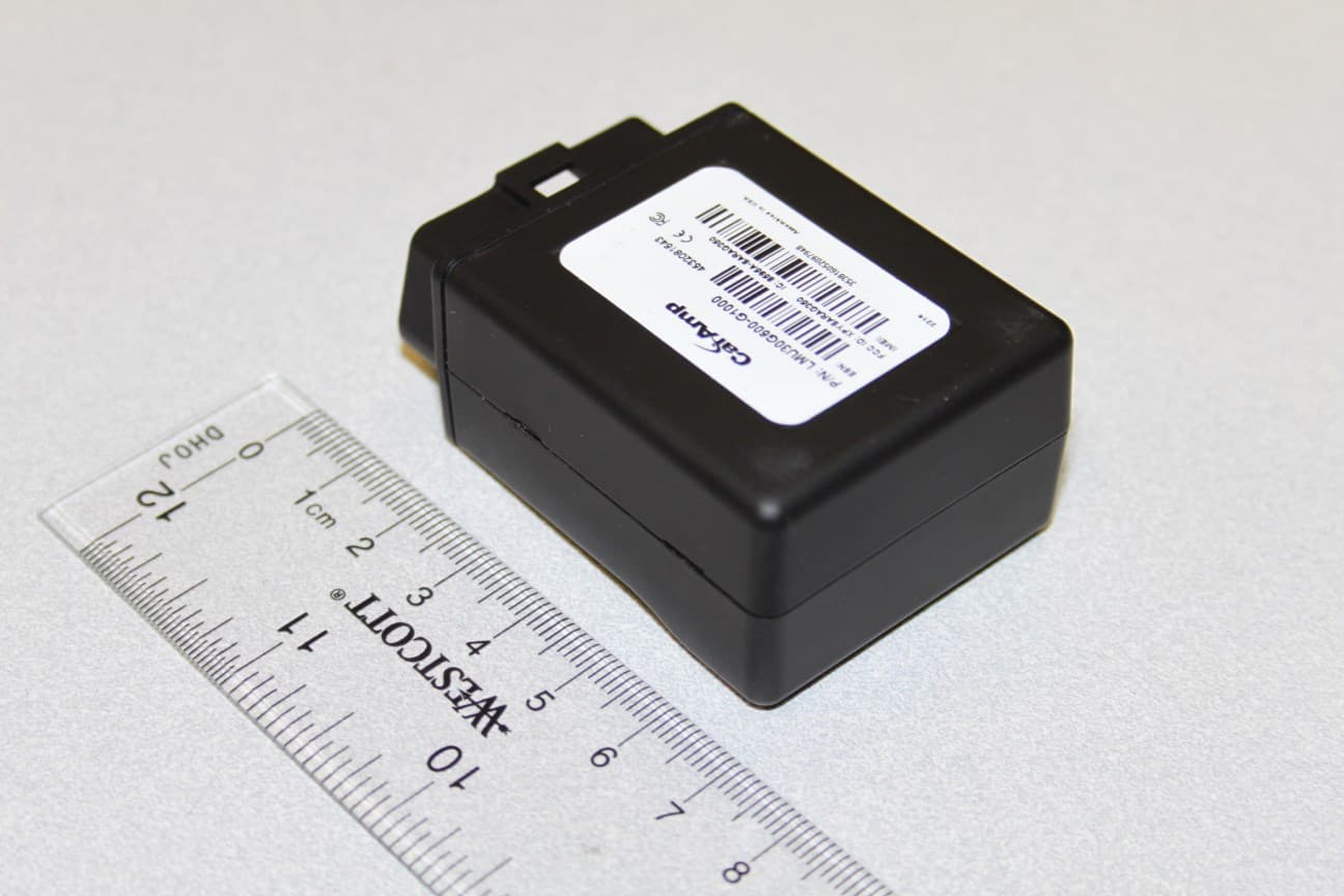
Click to zoom
Application Details
- Equipment Class
- PCB - PCS Licensed Transmitter
- Date of Grant
- Oct 27, 2014
- Application Purpose
- Original Equipment
- Date of Application
- Oct 27, 2014
- Equipment Note
- Vehicle tracking unit with GPS, GSM/GPRS/HSPA and Bluetooth.
- Frequency Range
- 1852.40000000 - 1907.60000000
- Company
- CalAmp
- Country
- United States
Documents & Files
Document Text
Text extracted from the exhibit documents filed with the FCC. Open a document above to read the original.
Users Manual
Application Note Version: 1.0 Feature: Bluetooth Support Page #: 1 of 11 LMU Bluetooth Chipset Application Note Boris Velev Application Note Version: 1.0 Feature: Bluetooth Support Page #: 2 of 11 1 Introduction ........................................................................................................................ 3 2 Description .......................................................................................................................... 3 3 Setup ................................................................................................................................... 4 3.1 LMU BT LE driver streams and serial port configuration parameters setup example. 4 3.2 LMU BTST SPP driver streams and serial port configuration parameters setup example. ................................................................................................................................. 4 3.3 LMU Bluetooth driver configuration parameters setup. ............................................ 5 3.4 LMU user serial message configuration parameters setup example......................... 6 3.5 BTCS version format. ................................................................................................... 7 3.6 BTCS default Pass key. ................................................................................................. 7 3.7 Verification of LMU BTST SPP mode “Data” state example. ...................................... 7 3.8 Verification of LMU configuration for BLE “connection” mode example. ................. 8 3.9 Verification of LMU BLE “Advert broadcast scanning” mode configuration example. ................................................................................................................................. 8 4 Usage .................................................................................................................................. 9 4.1 Demonstration of LMU BT SPP mode. ........................................................................ 9 4.2 Demonstration of BLE “connection” mode based remote temperature sensor device. .................................................................................................................................... 9 4.3 Demonstration of BLE “broadcast scanning” mode based remote KeyFob DriverID device. .................................................................................................................................. 11 Application Note Version: 1.0 Feature: Bluetooth Support Page #: 3 of 11 1 Introduction This application note documents the use of Bluetooth chipset device based on TI MSP430F5438A microcontroller and CC2564 RF processor. The BTCS device has Bluetooth LE4.0 dual mode capabilities. The firmware is based on Stonestreet One Bluetopia protocol stack. The document uses as an example the Texas Instruments CC 2541 Sensor Tag with the purpose of reading the temperature from TI TMP006 temperature sensor. A “KeyFob” device which broadcasts “Button xx press” events together with “battery charge state as percentage“ information is used as another example. 2 Description The BTCS device is connected to a LMU serial port. The BTCS unit supports Bluetooth SPP mode of operation. BTCS plays a server slave device which upon connection with a Remote Bluetooth client master device can exchange data. There are two Bluetooth low energy (BLE) modes of operation: “Connection” based and an “Advert Broadcast Scanning” mode. In “Connection” mode, the LMU firmware starts the discovery process of all BLE remote devices. If a match is found based on the remote address stored as an “APP PARAM 2082”, the discovery sequence is ended and the connection process starts. Upon the reception of “CONNECTED_OK” event, the user will be able to send setup commands to the remote device, and consequently receive the sensor data. In “Advert Broadcast scanning” mode BT driver simply receives the broadcast advertisements from all remote BLE devices. The block diagram is presented in Figure 1 below. Application Note Version: 1.0 Feature: Bluetooth Support Page #: 4 of 11 Figure 1 3 Setup 3.1 LMU BT LE driver streams and serial port configuration parameters setup example. • Map debug stream to Aux1 port. AT$APP PARAM 3072,3,0 • Bluetooth stream to AUX 2. AT$APP PARAM 3072,14,1 • A Bluetooth stream baud rate set to 115200 AT$APP PARAM 3073,14,12 • A Bluetooth stream set to 8, n, 1 AT$APP PARAM 3074,14,3 • User0 Stream to Bluetooth Port AT$APP PARAM 3072,0,8 3.2 LMU BTST SPP driver streams and serial port configuration parameters setup example. • LMU BT driver SPP mode setup: at$app param 2083,0,0 User Serial Tx Data BT STREAM BLE “AT cmd” Parser BT_DRV BT_ Sensor BT_ Sensor BT_DRV BT STREAM User Serial Rx Data BTCS BTCS SPP Application Note Version: 1.0 Feature: Bluetooth Support Page #: 5 of 11 • Turn off stream for User 0: at$app param 3072,0,255 • Map Debug stream to BT_port: at$app param 3072,3,8 • Reset LMU : ATRESET LMU debug log will be visible on BT remote Android device console upon connection. The connection process is initiated by Android master device. 3.3 LMU Bluetooth driver configuration parameters setup. • PID 2082 holds up to 8 remote device addresses 6 Bytes long. at$app param 2082,0,144,89,175,10,169,169 corresponding to remote device MAC address: 0x9059AF0AA9A9 The first location in the array of addresses above is used to establish a BLE connection to a remote BLE device in BLE” Connected” mode. All unused addresses must contain 255,255,255,255,255,255. • PID 2083 holds the mode of operation and it is 2 Bytes long. Bit 0 is used for mode selection 0- standard-SPP, and 1- Low Energy. For instance to configure BT driver in SPP mode use the following: at$app param 2083,0,0 For example in order to configure BT driver in BLE “Connection” mode use: at$app param 2083,0,1 Bit 1 defines if broadcast scanning is enabled 0 – disabled , 1 – enabled. Bit 2: 0- whitelist should be used to filter out th…
Text truncated - open the document above for the full version.
Users Manual
LMU-3030 Hardware & Installation Guide LMU-3030™ Hardware and Installation Guide IMPORTANT: DO NOT INSTALL OR USE THE SOFTWARE OR DOCUMENTATION UNTIL YOU HAVE READ AND AGREED TO THE LICENSE AGREEMENT AND REVIEWED THELIMITED WARRANTY AND REGULATORY INFORMATION. [edit][top]1 Introduction Welcome to the LMU-3030™ Hardware and Installation Guide. This manual is intended to give you information on the basic setup and installation of the CalAmp LMU-3030™ product(s) including hardware descriptions, environmental specifications, wireless network overviews and device installation. 1.1 About This Manual The LMU-3030™ is one of the most flexible economy mobile tracking hardware products available. In order to accurately describe the functionality of these units we have broken this manual into the following sections: System Overview – A basic description of a CalAmp LMU-3030™ based tracking system. This includes a description of roles and responsibilities of each of the CalAmp components as well as a brief overview of the wireless data technologies used by the LMU-3030™. Hardware Overview – Describes the physical characteristics and interfaces of the LMU-3030™. Installation and Verification – Provides guidance for the installation of the LMU-3030™ in a vehicle and instructions on how to verify the installation is performing adequately. 1.2 About the Reader In order to limit the size and scope of this manual, the following assumptions have been made about the reader. You are familiar with GPS concepts and terminology You have some experience with installing equipment in vehicles You are familiar with the use of AT Commands You are familiar with the use of terminal programs such as HyperTerminal or PuTTY 1.3 About CalAmp CalAmp is a leading provider of wireless communications products that enable anytime/anywhere access to critical information, data and entertainment content. With comprehensive capabilities ranging from product design and development through volume production, CalAmp delivers cost-effective high quality solutions to a broad array of customers and end markets. CalAmp is the leading supplier of Direct Broadcast Satellite (DBS) outdoor customer premise equipment to the U.S. satellite television market. The Company also provides wireless data communication solutions for the telemetry and asset tracking markets, private wireless networks, public safety communications and critical inf rastructure and process control applications. For additional information, please visit the Company’s website at www.calamp.com. 1.4 About the CalAmp Location Messaging Unit-LMU-3030™ The CalAmp Location and Messaging Unit-LMU-3030™ (LMU-3030™) is a mobile device that resides in private, commercial or government vehicles. The LMU-3030™ is a single box enclosure incorporating a processor, a GPS receiver, a wireless data modem, and a vehicle-rated power supply. The LMU-3030™ also supports inputs and outputs to monitor and react to the vehicular environment and/or driver actions. Flexibility The LMU-3030™ features CalAmp's industry leading advanced on-board alert engine that monitors vehicle conditions giving you the most flexible tracking device in its class. The PEG™ (Programmable Event Generator) application supports hundreds of customized exception-based rules to help meet customers' dynamic requirements. Customers can modify the behavior of the device to meet with a range of applications preprogrammed before shipment or in the field. Combining affordability and device intelligence with your unique application can give you distinct advantages over your competition. Over-the-Air Serviceability The LMU-3030™ also incorporates CalAmp's industry leading over-the-air device management and maintenance system software, PULS™ (Programming, Updates, and Logistics System). Configuration parameters, PEG rules, and firmware can all be updated over the air. Our web-based maintenance server, PULS™ scripts, and firmware, can all be updated over-the-air. PULS™ offers out-of-the-box hands free configuration and automatic post-installation upgrades. You can also monitor unit health status across your customers' fleets to quickly identify issues before they become expensive problems. 2 - System Overview 2.1 Overview The entire purpose behind a fleet management system is to be able to remotely contact a vehicle, determine its location or status, and do something meaningful with that information. This could include displaying the vehicle location on a map, performing an address look-up, providing real-time driving directions, updating the vehicles ETA, monitoring vehicle and driver status or dispatching the vehicle to its next pick up. These functions, of course, are completely dependent on the capabilities of the vehicle management application. The role of the CalAmp LMU-3030™ is to deliver the location information when and where it is needed. A typical fleet management system based on a CalAmp device includes the following components: A wireless data network An LMU-3030™ Host Device (GPS NMEA only) An LM Direct™ communications server Backend mapping and reporting software which typically includes mapping and fleet reporting functions PULS™ LMU Manager™ Basic System Architecture 2.2 Component Descriptions 2.2.1 Wireless Data Network The Wireless Data Network provides the information bridge between the LM Direct™ server and the LMU-3030™. Wireless data networks can take a variety of forms, such as cellular networks, satellite systems or local area networks. Contact the CalAmp sales team for the networks available to the LMU- 3030™. 2.2.2 LMU-3030™ The LMU-3030™ is responsible for delivering the location and status information when and where it is needed. Data requests mainly come from the following sources: PEG™ script within the LMU-3030™ A location or status request from the LM Direct™ server A location or status request from LMU Manager An SMS request made from a mobile device such as a custo…
Text truncated - open the document above for the full version.
Attestation Statements
A E R C E P T D A T A R A D I O L A N D C E L L O M E G A S MA R T L I N K www.calamp.com CalAmp / Mobile resource Management MRM/M2M Products 2177 Salk Ave, STE 200 Carlsbad, CA 92008 PH: (760) 438-9010 – Fax: (760) 438-5835 TUV SUD BABT TCB Octagon House, Segensworth Road, Fareham, Hampshire, PO15 5RL RE: FCC ID APV-3030HBT IC: 5843C-3030HBT M/N: LMU30H30BT3 By my signature below, I attest: The Datasheet sheet has general info to cover all LMU3030 variants: LMU 3030 CDMA, LMU3030 GPRS, and another one use u-Blox LISA U200 which support the 5 HSPA bands. The product specified above use the Gemalto EHS5-US (QIPEHS5-US) which support only two bands 850/1900 GPRS, EGPRS and WCDMA and can be found in the FCC docs of the cellular Radio Sincerely, October 27 2014 Product Certification Manager Imad Rizk Phone number: (760) 814-9697 Email: [email protected]
Attestation Statements
TÜV SÜD AMERICA INC 10040 Mesa Rim Road San Diego, CA 92121-2912 Phone: 858 678 1400 FAX: 858 546 0364 TÜV SÜD America Inc. (San Diego) October 22, 2014 TUV SUD BABT Octagon House, Concorde Way Segensworth Rd N, Fareham PO15 5RL RE: FCC ID APV-3030HBT IC: 5843C-3030HBT M/N: LMU30H30BT3 By my signature below, I attest: • That the Cinterion Wireless module, model: ESH5-US, which is integrated in this device, is unchanged. • That the original test data from CETECOM GmbH Test Report No.: 6-014712-9-3A and 6-147- 12-9-3b according to FCC Part 22H/24E and RSS-132/133 remain valid and applicable to Model LMU30H30BT3 and is/are representative of the compliance for this device. • That the original test data from CETECOM GmbH Test Report No.: 6-014712-9-3A and 6-147- 12-9-3b are compliant to the latest version of IC radio standards applied for (RSS-133 Issue 6 and RSS-132 Issue 3). Sincerely, Ferdinand S. Custodio EMC/Senior Wireless Test Engineer
Cover Letter(s)
A E R C E P T D A T A R A D I O L A N D C E L L O M E G A S MA R T L I N K www.calamp.com CalAmp / Mobile resource Management MRM/M2M Products 2177 Salk Ave, STE 200 Carlsbad, CA 92008 PH: (760) 438-9010 – Fax: (760) 438-5835 October 14, 2014 TUV SUD BABT TCB Octagon House, Segensworth Road, Fareham, Hampshire, PO15 5RL Re: FCC ID: APV-3030HBT IC: 5843C-3030HBT Dir Sir and Madam, We CalAmp 2177 Salk Ave, STE 100, Carlsbad, CA 92008 hereby authorize Ferdinand S Custodio at TUV SUD America, Inc. 10040 Mesa Rim Road, San Diego, CA 92121 Tel: (858) 678-1400 to act as our agent in all matters relating to applications for equipment authorization, including the signing of all documents relating to these matters. This authorization expire on February 15, 2015 Sincerely, Product Certification Manager Imad Rizk Phone number: (760) 814-9697 Email: [email protected]
Cover Letter(s)
A E R C E P T D A T A R A D I O L A N D C E L L O M E G A S MA R T L I N K www.calamp.com CalAmp / Mobile resource Management MRM/M2M Products 2177 Salk Ave, STE 200 Carlsbad, CA 92008 PH: (760) 438-9010 – Fax: (760) 438-5835 TUV SUD BABT TCB Octagon House, Segensworth Road, Fareham, Hampshire, PO15 5RL Confidentiality Request FCC ID: APV-3030HBT Pursuant to Sections 0.457(d)(1)(ii) and 0.459 of the Commission’s Rules, CalAmp Wireless networks hereby requests permanent confidential treatment of information accompanying this application as: Block Diagram Operation description Schematic Part list Also hereby requests short-term confidential treatment of information accompanying this application as outlined below for a period of 180 days: - Internal photos - External photos The above materials contain trade secrets and proprietary information not customarily released to the public. The public disclosure of these matters might be harmful to the Applicant and provide unjustified benefits to its competitors. The Applicant understands that pursuant to Rule 0.457(d)(1)(ii), disclosure of this Application and all accompanying materials will not be made before the date of the Grant for this Application. Sincerely, October 23 2014 Product Certification Manager Imad Rizk Phone number: (760) 814-9697 Email: [email protected]
External Photos
FCC ID APV-3030HBT IC: 5843C-3030HBT
ID Label/Location Info
UNLESS OTHERWISE SPECIFIED DIMENSIONS ARE IN INCHES TOLERANCES ARE: FRACTIONS DECIMALS ANGLES ±1/32 .XX ±.01 ±0°30’ .XXX ± .005 USED ON REVISIONS MATERIAL FINISH DRAWN: CHECKED: ISSUED: TITLE DO NOT SCALE DRAWING SIZE CAGE CODE DWG NO. REV A 6T925 SHEET 1 OF 1 SCALE ITEM NO. QTY REQD IDENTIFYING NO. DESCRIPTION MKTG: 1 1 LABEL BLANK, 1.5” x 1.0”, 1.0” SPOOL SIZE 79-00326 NOTES: UNLESS OTHERWISE SPECIFIED 1. APPLICABLE STANDARDS / SPECIFICATIONS; MIL-STD-100E, ENGINEERING DRAWING PRACTICES. ANSI Y14.5M-1982, DIMENSIONS AND TOLERANCES. 2. FONT : BARCODE FORMAT 39, BLACK INK 3. DATE CODE SHALL BE DEFINED AS : WWYY WW – TWO DIGIT WORK WEEK YY – TWO DIGIT YEAR 4. MATERIAL MUST BE LEAD (Pb) FREE PER THE EUROPEAN UNION’S RESTRICTION OF HAZARDOUS SUBSTANCE (RoHS) DIRECTIVE. A. HARGITAI MM/DD/YYYY D. PATEL 09/10/2014 A. ANGELES MM/DD/YYYY 134671-G1000 A REV ECO NO. DESCRIPTION DATE APPROVED A PRODUCTION RELEASE 10/07/2014 D. PATEL LABEL MARKING, UNIT, LMU3030, GEMALTO HSPA, BLUETOOTH, 3LED, SERIAL, GEN-HW LMU30H30BT3-G1000 Elec. File: 134671-G1000_A.doc 3 1” 1.5” WWYY P/N: LMU30H30BT3 CC:G1000 Assembled in China FCC ID: APV-3030HBT IC: 5843C-3030HBT nnnnnnnnnn ESN nnnnnnnnnnnnnnn IMEI
ID Label/Location Info
FCC ID APV-3030HBT IC: 5843C-3030HBT Label Location
Internal Photos
FCC ID APV-3030HBT IC: 5843C-3030HBT
RF Exposure Info
TÜV SÜD AMERICA INC 10040 Mesa Rim Road San Diego, CA 92121-2912 Phone: 858 678 1400 FAX: 858 546 0364 October 22, 2014 TUV SUD BABT Octagon House, Concorde Way Segensworth Rd N, Fareham PO15 5RL Attention: Director of Certification RE: Analysis of RF Exposure for Portable use per Title 47, Part 1 Subpart I, §1.1310, Title 47, Part 2 Subpart J, §2.1091 and RSS-102 Issue 4 March 2010. FCC ID: APV-3030HBT IC: 5843C-3030HBT 1. Mobile MPE Calculation Summary using a 20cm separation distance: Mode Output Power Antenna Gain Power Density (mW/m 2 ) GSM/GPRS 850 33.20 dBm (837.0 MHz) -9.8 dBi* 0.0435 GSM/GPRS 1900 30.47 dBm (1880.0 MHz) -4.5 dBi* 0.0787 WCDMA FDD V 23.84 dBm (826.40 MHz) -9.8 dBi* 0.0050 WCDMA FDD II 24.80 dBm (1880.0 MHz) -4.5 dBi* 0.0213 Bluetooth 100.4 dBμV/m @ 3 meters 0 dBi 0.00065441 Bluetooth LE 86.6 dBμV/m @ 3 meters 0 dBi 0.00002728 2. Co-Located Transmitters transmission table: Transmitter type Transmitter type that can transmit at the same time GSM/GPRS 850 Bluetooth GSM/GPRS 850 Bluetooth LE GSM/GPRS 1900 Bluetooth GSM/GPRS 1900 Bluetooth LE WCDMA FDD II Bluetooth WCDMA FDD II Bluetooth LE WCDMA FDD V Bluetooth WCDMA FDD V Bluetooth LE TÜV SÜD AMERICA INC 10040 Mesa Rim Road San Diego, CA 92121-2912 Phone: 858 678 1400 FAX: 858 546 0364 3. Simultaneous Transmission MPE (Worst Case Combination): Transmitter type MPE (mw/cm 2 ) Limit (mW/cm 2 ) MPE ratio (MPE/Limit) GSM/GPRS 1900 0.0787 1.0 0.0787 Bluetooth 0.00065441 1.0 0.00065441 Sum of the ratios (should be <1.0) 0.07935441 4. Mobile MPE Calculation using a 20cm separation distance (GSM/GPRS 850): Using Power Density formula: S= PG 4πR 2 where: S = power density P = power input to the antenna G = power gain of the antenna in the direction of interest relative to isotropic R = distance to the center of radiation of the antenna Maximum peak output power at antenna input terminal: 33.20 (dBm) Maximum peak output power at antenna input terminal: 2089.30 (mW) Antenna gain(typical): -9.8 (dBi) Maximum antenna gain: 0.105 (numeric) Prediction distance: 20 (cm) Sourse Based Time Average Duty Cycle: 100 (%) Prediction frequency: 837 (MHz) MPE limit for uncontrolled exposure at prediction frequency: 0.558 (mW/cm 2 ) Power density at prediction frequency: 0.0435 (mW/cm 2 ) Power density at prediction frequency: 0.435 (W/m 2 ) Margin of Compliance: -11.08 (dB) 5. Mobile MPE Calculation using a 20cm separation distance (GSM/GPRS 1900): Maximum peak output power at antenna input terminal: 30.47 (dBm) Maximum peak output power at antenna input terminal: 1114.29 (mW) Antenna gain(typical): -4.5 (dBi) Maximum antenna gain: 0.355 (numeric) Prediction distance: 20 (cm) Sourse Based Time Average Duty Cycle: 100 (%) Prediction frequency: 1880 (MHz) MPE limit for uncontrolled exposure at prediction frequency: 1.000 (mW/cm 2 ) TÜV SÜD AMERICA INC 10040 Mesa Rim Road San Diego, CA 92121-2912 Phone: 858 678 1400 FAX: 858 546 0364 Power density at prediction frequency: 0.0787 (mW/cm 2 ) Power density at prediction frequency: 0.787 (W/m 2 ) Margin of Compliance: -11.04 (dB) TÜV SÜD AMERICA INC 10040 Mesa Rim Road San Diego, CA 92121-2912 Phone: 858 678 1400 FAX: 858 546 0364 6. Mobile MPE Calculation using a 20cm separation distance (WCDMA FDD II): Maximum peak output power at antenna input terminal: 23.84 (dBm) Maximum peak output power at antenna input terminal: 242.10 (mW) Antenna gain(typical): -9.8 (dBi) Maximum antenna gain: 0.105 (numeric) Prediction distance: 20 (cm) Sourse Based Time Average Duty Cycle: 100 (%) Prediction frequency: 826.4 (MHz) MPE limit for uncontrolled exposure at prediction frequency: 0.550 (mW/cm 2 ) Power density at prediction frequency: 0.0050 (mW/cm 2 ) Power density at prediction frequency: 0.050 (W/m 2 ) Margin of Compliance: -20.38 (dB) 7. Mobile MPE Calculation using a 20cm separation distance (WCDMA FDD V): Maximum peak output power at antenna input terminal: 24.80 (dBm) Maximum peak output power at antenna input terminal: 302.00 (mW) Antenna gain(typical): -4.5 (dBi) Maximum antenna gain: 0.355 (numeric) Prediction distance: 20 (cm) Sourse Based Time Average Duty Cycle: 100 (%) Prediction frequency: 1880 (MHz) MPE limit for uncontrolled exposure at prediction frequency: 1.000 (mW/cm 2 ) Power density at prediction frequency: 0.0213 (mW/cm 2 ) Power density at prediction frequency: 0.213 (W/m 2 ) Margin of Compliance: -16.71 (dB) TÜV SÜD AMERICA INC 10040 Mesa Rim Road San Diego, CA 92121-2912 Phone: 858 678 1400 FAX: 858 546 0364 8. Mobile MPE Calculation using a 20cm separation distance (Bluetooth): Measured Field Strength --Radiated: 100.4 (dBuV/m) Maximum peak output power --Radiated: 0.0032894 (W) Antenna gain(typical): 0.00 (dBi) Maximum antenna gain: 1.00 (numeric) Prediction distance: 20.00 (cm) Prediction frequency: 319.00 (MHz) Limit from table below: 1 (mW/cm 2 ) Power density at prediction frequency: 0.00065441 (mW/cm 2 ) Margin of Compliance: -31.84 (dB) 9. Mobile MPE Calculation using a 20cm separation distance (Bluetooth LE): Measured Field Strength --Radiated: 86.6 (dBuV/m) Maximum peak output power --Radiated: 0.0001371 (W) Antenna gain(typical): 0.00 (dBi) Maximum antenna gain: 1.00 (numeric) Prediction distance: 20.00 (cm) Prediction frequency: 319.00 (MHz) Limit from table below: 1 (mW/cm 2 ) Power density at prediction frequency: 0.00002728 (mW/cm 2 ) Margin of Compliance: -45.64 (dB) *Notes: Power level and worst case channel information for the cellular radio were derived from the test reports of the original filing. Antenna gains information of the cellular radio were derived from a reference cellular module testing using CTIA Over The Air Performance Summation Test Report (7 layers, Inc. Project Name: MUS_CALAMP_1310) provided by the client. Sincerely, Ferdie S. Custodio Name Authorized Signatory Title: EMC/ Senior Wireless Test Engineer
Test Report
Page 1 of 39 The test results relate only to the individual items which have been tested. This report shall not be reproduced in parts without the written approval of the testing laboratory © Copyright: All rights reserved by CETECOM Laboratory Accreditation and Listings Reg. No.: 736496 MRA US-EU 0003 Industry Canada Reg. No.: 3462D-1 Reg. No.: 3462D-2 Reg. No.: 3462D-3 Voluntary Controls for Electromagnetic Emissions Reg. No.: R-2665, R-2666 C-2914, T-1967, G-301 accredited according to DIN EN ISO/IEC 17025 CETECOM GmbH Laboratory Radio Communications & Electromagnetic Compatibility Im Teelbruch 116 • 45219 Essen • Germany Registered in Essen, Germany, Reg. No.: HRB Essen 8984 Tel.: + 49 (0) 20 54 / 95 19-954 • Fax: + 49 (0) 20 54 / 95 19-964 E-mail: [email protected] • Internet: www.cetecom.com TEST REPORT No.: 6-0147-12-9-3a for EHS5-US Module FCC-ID: QIPEHS5-US IC: 7830A-EHS5US According to: FCC Regulations CFR47: Part 22 Part 24 IC Regulations RSS Gen, Issue 3 RSS-132, Issue 2 RSS-133, Issue 5 Cinterion Wireless Modules GmbH Test Report 6-0147-12-9-3a, Page 2 of 39 TR6-0147-12-9-3a.doc Table of contents 1. SUMMARY OF TEST RESULTS...................................................................................................................... 3 1.1. TX mode, tests overview FCC and Canada IC Standards (RSS) ..................................................................... 3 1.2. Attestation:....................................................................................................................................................... 4 2. ADMINISTRATIVE DATA ............................................................................................................................... 5 2.1. Identification of the testing laboratory ............................................................................................................. 5 2.2. Test location .................................................................................................................................................... 5 2.3. Organizational items ........................................................................................................................................ 5 2.4. Applicant‟s details ........................................................................................................................................... 5 2.5. Manufacturer‟s details ..................................................................................................................................... 5 3. EQUIPMENT UNDER TEST (EUT) ................................................................................................................. 6 3.1. TECHNICAL DATA OF MAIN EUT DECLARED BY APPLICANT ......................................................... 6 3.2. EUT: Type, S/N etc. and short descriptions used in this test report ................................................................ 7 3.3. Auxiliary Equipment (AE): Type, S/N etc. and short descriptions .................................................................. 7 3.4. EUT set-ups ..................................................................................................................................................... 7 3.5. EUT operating modes ...................................................................................................................................... 8 3.6. Parameter Settings on mobile phone and base station CMU200 ..................................................................... 9 3.7. Configuration of cables used for testing .......................................................................................................... 10 4. DESCRIPTION OF TEST SYSTEM SET-UP’S .............................................................................................. 11 4.1. Test system set-up for conducted measurements at antenna port .................................................................... 11 4.2. Test system set-up for radiated spurious emission measurements ................................................................... 12 5. MEASUREMENTS ............................................................................................................................................. 13 5.1. RF-Parameter - RF Peak power output conducted ........................................................................................... 13 5.2. RF-Parameter - RF Peak power output radiated .............................................................................................. 15 5.3. RF-Parameter - Occupied bandwidth and emission bandwidth ....................................................................... 17 5.4. RF-Parameter - Conducted out of Band RF emissions and Band Edge ........................................................... 19 5.5. RF-Parameter - Radiated out of Band RF emissions and Band Edge .............................................................. 23 5.6. RF-Parameter - Frequency stability on temperature and voltage variations .................................................... 25 5.7. Measurement uncertainties .............................................................................................................................. 34 6. ABBREVIATIONS USED IN THIS REPORT ................................................................................................. 34 7. ACCREDITATION DETAILS OF CETECOM’S LABORATORIES AND TEST SITES ......................... 35 8. INSTRUMENTS AND ANCILLARY ................................................................................................................ 36 8.1. Used equipment “CTC” ................................................................................................................................... 36 Table of annex Total pages Annex 1: External photos 4 Annex 2: Internal photos 4 Annex 3: Test set-up photos 4 Annex 4: Measurement diagrams 60 The listed attachments are an in…
Text truncated - open the document above for the full version.
Test Report
Annex 4 to Test Report 6-0147-12-9-3, Page 1 of 60 TR6-0147-12-9-3a_A4.doc Laboratory Accreditation and Listings Reg. No.: 736496 MRA US-EU 0003 Industry Canada Reg. No.: 3462D-1 Reg. No.: 3462D-2 Reg. No.: 3462D-3 Voluntary Controls for Electromagnetic Emissions Reg. No.: R-2665, R-2666 C-2914, T-1967, G-301 accredited according to DIN EN ISO/IEC 17025 CETECOM GmbH Laboratory Radio Communications & Electromagnetic Compatibility Im Teelbruch 116 • 45219 Essen • Germany Registered in Essen, Germany, Reg. No.: HRB Essen 8984 Tel.: + 49 (0) 20 54 / 95 19-954 • Fax: + 49 (0) 20 54 / 95 19-964 E-mail: [email protected] • Internet: www.cetecom.com Annex 4: Measurement diagrams to TEST REPORT No.: 6-0147-12-9-3 for EHS5-US Module FCC-ID: QIPEHS5-US IC: 7830A-EHS5US According to: FCC Regulations CFR47: Part 22, Part …
Text truncated - open the document above for the full version.
Contact Information
Applicant
Imad Rizk(Carrier & Product Certifications Manager)
Test Firm
cetecom advanced GmbHGerald Schmidt
Technical Specifications
| # | Rule Parts | Frequency Range | Power Output | Emission | Tolerance |
|---|---|---|---|---|---|
| 6 | 24E | 1.85 GHz - 1.91 GHz | 240.00 mW | 4M07F9W | 2.5 ppm |
Other Applications from CalAmp
APV-TTU3640LAB
Apr 23, 2026Vehicular Telematics Device
Equipment Class
PCB - PCS Licensed TransmitterAPV-4350LB
May 07, 2024LTE CAT1 Telematics Gateway
Equipment Class
DTS - Digital Transmission System
APV-3640LB
Dec 14, 2023Heavy Duty Telematics Gateway
Equipment Class
PCB - PCS Licensed Transmitter
APV-3642MB
Jul 11, 2023LTE CAT-M1 Telematics Gateway
Equipment Class
PCB - PCS Licensed Transmitter
APV-2650MB
Apr 02, 2023Remote location monitoring unit.
Equipment Class
PCB - PCS Licensed Transmitter