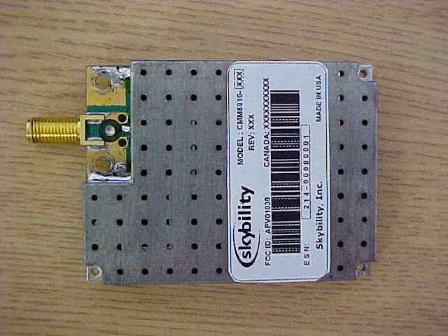
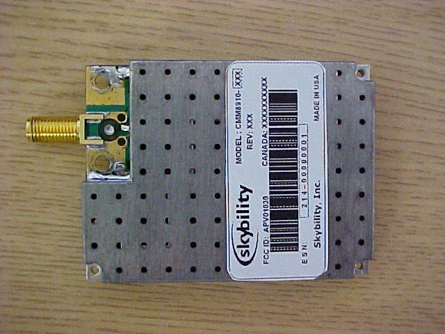
APV01030Cellular Module
CalAmp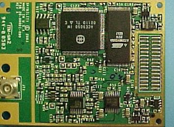
Click to zoom
Application Details
- Equipment Class
- TNB - Licensed Non-Broadcast Station Transmitter
- Date of Grant
- Feb 26, 2003
- Application Purpose
- Original Equipment
- Date of Application
- Feb 26, 2003
- Equipment Note
- Cellular Module
- Frequency Range
- 824.04000000 - 848.97000000
- Company
- CalAmp
- Country
- United States
Documents & Files
Document Text
Text extracted from the exhibit documents filed with the FCC. Open a document above to read the original.
Cover Letter(s)
February 6, 2003 attn: Reviewing Engineer Federal Communications Commission 7435 Oakland Mills Road Columbia, MD 21046 RE: CONFIDENTIALITY REQUEST FOR: CMM7900, CMM7910, CMM8900, CMM8910 FCC ID#: APV01030 To Whom It May Concern: This letter serves as an official request for confidentiality under FCC Rule Section 0.459. We have requested that the following documents are wholly-owned intellectual property of Skybility and as such must never be divulged or allowed to be divulged to competitors within our industry. The Integration Guide is included in the list of confidential documents as it is disclosed only under the protection of a Non-Disclosure Agreement executed between Skybility and our customers. Please contact me if there is any information you may need. Sincerely, Steve Hall Executive VP & Chief Technical Officer
Cover Letter(s)
March 3, 2003 Federal Communications Commission Office of Engineering Technology Application Processing Branch Attn: Reviewing Engineer Ref: APV01030 Model CMM7900, CMM7910,CMM8900,CMM8910 Dear Reviewing Engineer, The products represented in these authorization filings, (Skybility models CMM7900, CMM7910, CMM8900, and CMM8910), will be marketed and sold only as OEM modules for integration into OEM products. These products are sold in sub-assembly form and require additional integration work to incorporate them into a final product. These products are not offered for sale to the general public. If you require additional information regarding these products, I can be contacted by EMAIL at [email protected] or by telephone at (760) 268-5862. Sincerely, Steve Hall Executive VP & Chief Technical Officer
ID Label/Location Info
RevisedFeb11'03 Jan15'03 (2) 20mm(1) 4 - 2R 40mm Note: A. (1) is ESN ex. 214 - 00000001 Fixed number8 digits sequential number B. (2) is type of Antenna connector 001: SMA End Launch type 004: MCX Straight type C: Material-----------Scotchcal seal 0.05 Thickness Silver Mylar with self adhesive backing D: Print Color-------Black ink as UV Model Label Specifications
Internal Photos
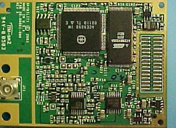
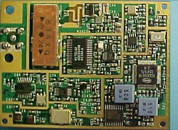
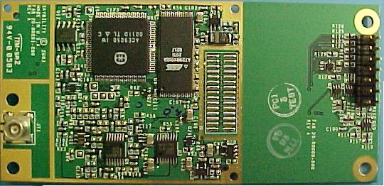
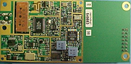
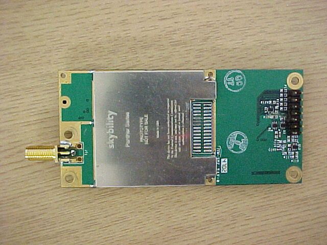
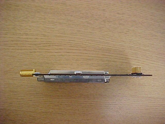
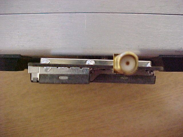
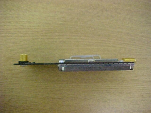
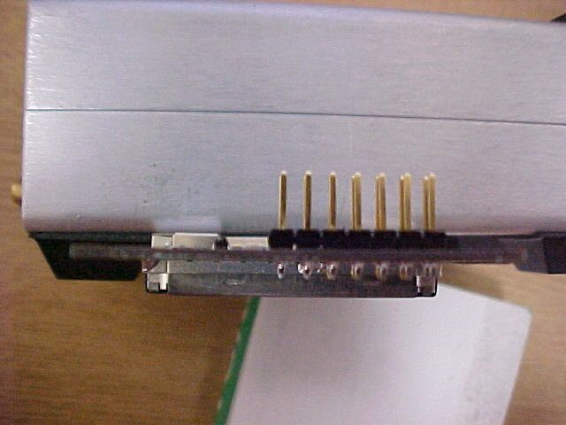
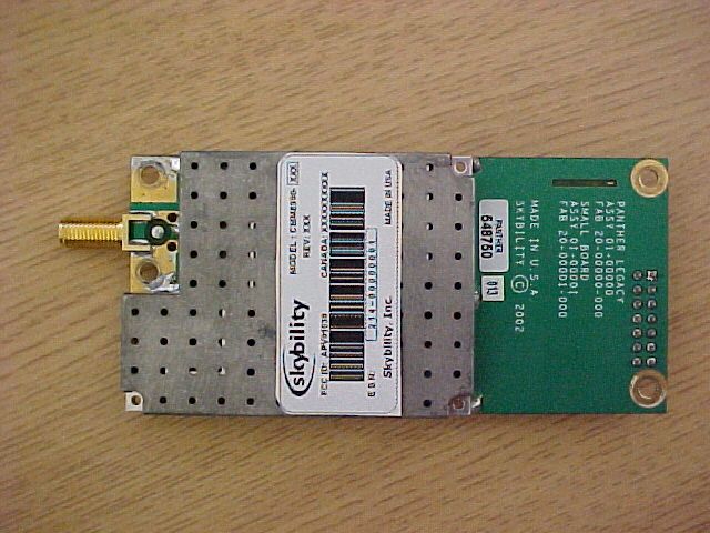
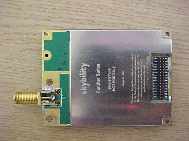
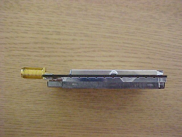
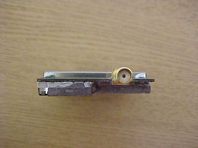
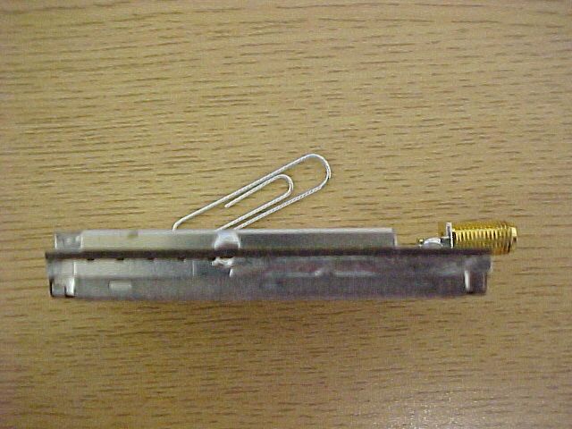
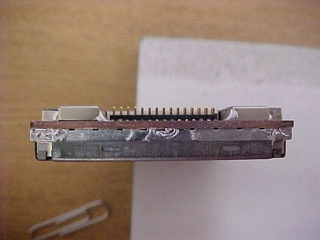
Please see external photos . They are the same for internal photos due to type of device.
Parts List/Tune Up Info
February 28, 2003 Federal Communications Commission Office of Engineering Technology Application Processing Branch Attn: Reviewing Engineer Ref: APV01030 Model CMM7900, CMM8900 APV01031 Model CMM7910, CMM8910 Dear Reviewing Engineer, The referenced devices are factory tuned and aligned only. If you require additional information regarding these products, I can be contacted by EMAIL at [email protected] or by telephone at (760) 268-5862. Sincerely, Steve Hall Executive VP & Chief Technical Officer
Test Report
Close From: Kerwinn Corpuz To: Marianne Bosley Cc: Jinae Lawson; Alvin Ilarina Subject: RE: Request for Technical Information for #13166 Skybility Sent: 2/24/2003 1:36 PM Importance: Normal HI Marianne, I'm sorry for the delay. I hope I answered your questions correctly. Below each question, answers are in red font. Thanks, Kerwinn -----Original Message----- From: Marianne Bosley Sent: Friday, February 21, 2003 12:11 PM To: Kerwinn Corpuz Cc: Jinae Lawson Subject: Request for Technical Information for #13166 Skybility Good Afternoon, The TCB engineer reviewed your application and has the following questions that need to be answered before we can finish. Please respond to me and I will forward: 1. Please provide the calculations necessary to determine the necessary bandwidth of the EUT, per Section. 2.202. Also, please justify the choice of emission designator. Description of Emission: Telemetry with digital frequency modulation. Formula: Bn=2M+2D. Calculation: M=10000, D=8000, Bandwidth=36000 or 36 kHz Designation of Emission: 36k0F1D 2. Please provide occupied bandwidth measurement plots. Occupied Bandwidth measurement procedure per 2.1049 and limits was applied per 22.917(d), Emission Mask. Included in report. Marianne T. Bosley EMC Administrator 410-354-3300 X 412 [email protected] Visit MET Labs for a demonstration of our new CETECOM BITE Test System at the Bluetooth Developers Conference, Booth 622, Dec. 10-12, San Jose, CA. For more information visit www.ibctelecoms.com/bluetoothdevcon. MET’S IN THE NEWS! Get the latest at: http://www.metlabs.com/pages/Sun.html?coll=bal -business-headlines
Test Report
Close From: Marianne Bosley To: Kerwinn Corpuz Cc: Jinae Lawson; Cheryl Anicete; Marianne Bosley Subject: #13166 Skybility - MPE Calculation Sent: 2/25/2003 4:25 PM Importance: Normal Hello again, One final thing: Users/Install manual states gain of 3-5 dB. Confirm that MPE Calculation allows this. You can show calculation as a separate exhibit instead of amending report. (An example of formula is attached from another report). Any questions, let me know. Marianne MPE Calculation.pdf M arianne T. Bosley EMC Administrator 410-354-3300 X 412 [email protected] Visit MET Labs for a demonstration of our new CETECOM BITE Test System at the Bluetooth Developers Conference, Booth 622, Dec. 10-12, San Jose, CA. For more information visit www.ibctelecoms.com/bluetoothdevcon. MET’S IN THE NEWS! Get the latest at: http://www.metlabs.com/pages/Sun.html?coll=bal-business-headlines
Test Report
RF Exposure Requirements – 1.1307(b)(2); 1.1310 Specification: Systems operating under the provisions of this section shall be operated in a manner that ensures that the public is not exposed to radio frequency energy levels in excess of the Commission’s Guidelines. EUT meets the requirements of these sections. MPE CALCULATION MPE Limit Calculation: EUT’s lowest frequency channel @ 824.04 MHz; therefore, f/1500 = Power Density (mW/cm 2 ), where f = frequency (MHz) Limit for Uncontrolled exposure: 0.54936 mW/cm 2 or 5.4936 W/m 2 Equation from page 18 of OET 65, Edition 97-01 S = PG / 4πR 2 = 1.26W*2.15dBi / 4*3.14*(0.2m) 2 = 2.709W / 0.5026m 2 = 5.39 W/m 2 where, S = Power Density (W/m 2 ) P = Power Input to antenna (1.26 Watts) G = Antenna Gain (2.15 dBi) R = distance to the center of radiation of the antenna (20 cm or 0.2 m) The power density @ 20cm = 5.39 W/m 2 , therefore EUT meets the Uncontrolled exposure limit.
Test Report
The Nation's First Licensed Nationally Recognized Testing Laboratory Conceil canadien des nomes Organisme de certification accedite Standards Council of Canada Accredited Certification Organization TM MET Laboratories, Inc. Safety Certification - EMI - Telecom Environmental Simulation 33439 WESTERN AVENUE ! UNION CITY, CALIFORNIA 94587-3201 ! PHONE (510) 489-6300 ! FAX (510) 489-6372 February 10, 2003 Skybility 2236 Rutherford Roads, Suite 103 Carlsbad, CA 92008 Reference:800 MHz Cellular Module Dear Mr. Paul A. Wardner, Enclosed is the EMC Test Report for the Skybility, 800 MHz Cellular Module tested to the requirements of the FCC Rules and Regulations, Part 22 Subpart H, of Title 47 of the CFR, for a Cellular Radiotelephone Service. Thank you for using the testing services of MET Laboratories. If you have any questions regarding these results or if MET can be of further assistance to you, please feel free to contact me. We appreciate your business and look forward to working with you again soon. Kindest Regards, MET LABORATORIES, INC. Cheryl Anicete Documentation Department Enclosures: (\Skybility\EMCS13166-FCC22.rpt) DOCTEM-23 Jan 02 Certificates and reports shall not be reproduced except in full, without the written permission of MET Laboratories, Inc. While use of the National Voluntary Laboratory Accreditation Program (NVLAP) letters or the NVLAP Logo in this report reflects the MET Accreditation under the NVLAP Program, these letters, logo, or Statements do not claim product endorsement by NVLAP or any Agency of the U.S. Government. The Nation's First Licensed Nationally Recognized Testing Laboratory MET Laboratories, Inc. Safety Certification - EMI - Telecom Environmental Simulation 33439 WESTERN AVENUE ! UNION CITY, CALIFORNIA 94587-3201 ! PHONE (510) 489-6300 ! FAX (510) 489-6372 Electro-Magnetic Compatibility Test Report for the Skybility 800 MHz Cellular Module Tested Under FCC Part 22, Subpart H Title 47 of the CFR for Cellular Radiotelephone Service MET REPORT: EMCS13166-FCC22 February 10, 2003 PREPARED FOR: Skybility 2236 Rutherford Roads, Suite 103 Carlsbad, CA 92008 PREPARED BY: MET Laboratories, Inc. 33439 Western Avenue Union City, California 94587 Copyright 2003, MET Laboratories, Inc. This report shall not be reproduced except in full, without the express written consent of MET Laboratories, Inc., nor shall this report, or any copy thereof be provided to a competitor of MET Laboratories, Inc. Skybility800 MHz Cellular Module February 10, 2003 MET# EMCS13166-FCC22Copyright 2003, MET Laboratories, Inc.Page i of vi Electro-Magnetic Compatibility Test Report for the Skybility 800 MHz Cellular Module Tested Under FCC Part 22 Subpart H Title 47 of the CFR for Cellular Radiotelephone Service MET REPORT: EMCS13166-FCC22 PREPARED FOR: Skybility 2236 Rutherford Roads, Suite 103 Carlsbad, CA 92008 _______________________________ Alvin Ilarina, Manager Electromagnetic Compatibility Testing _______________________________ Cheryl Anicete Documentation Department Engineering Statement: The measurements shown in this report were made in accordance with the procedures indicated, and the emissions from this equipment were found to be within the limits applicable. I assume full responsibility for the accuracy and completeness of these measurements, and for the qualifications of all persons taking them. It is further stated that upon the basis of the measurements made, the equipment tested is capable of operation in accordance with the requirements of Part 22, Subpart H, of the FCC Rules under normal use and maintenance. _______________________________ Kerwinn Corpuz Project Engineer Skybility800 MHz Cellular Module February 10, 2003 MET# EMCS13166-FCC22Copyright 2003, MET Laboratories, Inc.Page ii of vi REPORT STATUS SHEET RevisionReport/Revision DateReason for Revision iFebruary 10, 2003 Initial Issue . Skybility800 MHz Cellular Module February 10, 2003 MET# EMCS13166-FCC22Copyright 2003, MET Laboratories, Inc.Page iii of vi TABLE OF CONTENTS I.Executive Summary...........................................................................1 A.Purpose of Test .......................................................................2 B.Executive Summary....................................................................2 II.General.....................................................................................3 A.Test Site.............................................................................4 B.Description of Test Sample ..............................................................4 C.General Test Setup ....................................................................4 D.Mode of Operation ....................................................................4 F.Modification .........................................................................7 G.Disposition of Test Sample ..............................................................7 III.Electromagnetic Compatibility RF Power Output Requirements........................................8 A.RF Power Output......................................................................9 IV.Electromagnetic Compatibility Modulation Characteristics Requirements................................11 A.Modulation Characteristics.............................................................12 V.Electromagnetic Compatibility Occupied Bandwidth Requirements....................................13 A.Occupied Bandwidth ..................................................................14 VI.Electromagnetic Compatibility Spurious Emissions at Antenna Terminal Requirements.....................19 A.Spurious Emissions at Antenna Terminals .................................................20 B.Mobile Emissions in Base Frequency Range ...............................................23 VII. Electromagnetic Compatibility Radiated Emissions Requirements......................................26 A.Radiated Emissions (Substitution Method)................................…
Text truncated - open the document above for the full version.
Test Report
Skybility800 MHz Cellular Module February 10, 2003 MET# EMCS13166-FCC22Copyright 2003, MET Laboratories, Inc.Page 19 of 45 VI. Electromagnetic Compatibility Spurious Emissions at Antenna Terminal Requirements Skybility800 MHz Cellular Module February 10, 2003 MET# EMCS13166-FCC22Copyright 2003, MET Laboratories, Inc.Page 20 of 45 VI. Electromagnetic Compatibility Spurious Emissions at Antenna Terminal Requirements A. Spurious Emissions at Antenna Terminals Technical Specifications:§2.1051 and §22.917(e) Test equipment:Test equipment for Spurious Emissions at Antenna Terminals is listed in Section IX of this report. Photograph: Photograph 4. Spurious Emissions at Antenna Terminals Test Setup Photo Skybility800 MHz Cellular Module February 10, 2003 MET# EMCS13166-FCC22Copyright 2003, MET Laboratories, Inc.Page 21 of 45 VI. Electromagnetic Compatibility Spurious Emissions at Antenna Terminal Requirements Measurement Procedures:As required by 47 CFR 2.1051, spurious emissions at antenna terminal measurements were made at the RF output terminals using a 10 dB attenuator and a Spectrum Analyzer. Set a 10.5 dB Reference Level Offset and RBW = VBW = 30 kHz to Spectrum Analyzer. The EUT was set to transmit in the middle of the operating frequency range. The EUT was limited to have a burst of 5 second when transmitting at full power. To capture the modulated full power spurious emissions, activated the EUT at the lowest power then set the maximum power level button from HOST, repeated this step until the sweep is complete from 1 MHz to the 10 th harmonic of the fundamental. The Display Line was set to - 13 dBm as the limit line. Plotted the Spurious Emissions graph. Repeated measurements for both 10 kHz NRZ FSK and 6 kHz FM modulation. Measured Output Power of EUT: 1.26 Watts Spur limit = Po - (43 + 10logPo); Po = 1.26 watts or 31 dBm 31dBm - (43 + 10log 1.26) = 31 dBm - (44 dB) = -13 dBm Results:Equipment complies with Section 2.1051 and 22.917(e). The following pages show measurements of Spurious Emission plots which is recorded below: 10 kHz NRZ FSK Modulation Plot #Comment 7Middle Channel (834.99 MHz) Spurious Emissions 6 kHz FM Modulation Plot #Comment 8Middle Channel (834.99 MHz) Spurious Emissions The following plots are included to illustrate compliance with the required rule parts. Skybility800 MHz Cellular Module February 10, 2003 MET# EMCS13166-FCC22Copyright 2003, MET Laboratories, Inc.Page 22 of 45 VI. Electromagnetic Compatibility Spurious Emissions at Antenna Terminal Requirements Plot #7: Middle Channel (834.99 MHz) Out of Band Emissions with -13dBm Display Line Plot #8: Middle Channel (834.99 MHz) Out ot Band Emissions with -13 dBm Display Line Test Engineer:Kerwinn Corpuz Test Date:01/30/03 Skybility800 MHz Cellular Module February 10, 2003 MET# EMCS13166-FCC22Copyright 2003, MET Laboratories, Inc.Page 23 of 45 VI. Electromagnetic Compatibility Spurious Emissions at Antenna Terminal Requirements B.Mobile Emissions in Base Frequency Range Technical Specifications:§22.917(f) Test equipment:Test equipment for Mobile Emissions in Base Frequency Range at Antenna Terminals is listed in Section IX of this report. Photograph: Photograph 5. Mobile Emissions in Base Frequency Range at Antenna Terminals Test Setup Photo Skybility800 MHz Cellular Module February 10, 2003 MET# EMCS13166-FCC22Copyright 2003, MET Laboratories, Inc.Page 24 of 45 VI. Electromagnetic Compatibility Spurious Emissions at Antenna Terminal Requirements Measurement Procedures:As required by 47 CFR 22.917 (f), mobile emissions in base frequency range at antenna terminal measurements were made at the RF output terminals using a 10 dB attenuator and a Spectrum Analyzer. Set a 10.5 dB Reference Level Offset and RBW = 1 kHz, VBW = 30 kHz to Spectrum Analyzer. RBW was set to 1 kHz to improve the Spectrum Analyzer noise floor. The EUT was set to transmit in the middle of the operating frequency range. The EUT was limited to have a burst of 5 second when transmitting at full power. To capture the modulated full power spurious emissions, activated the EUT at the lowest power then set the maximum power level button from HOST, repeated this step until the sweep is complete from 869 MHz to 894 MHz. The Display Line was set to -80 dBm as the limit line. Plotted the emissions graph. Repeated measurements for both 10 kHz NRZ FSK and 6 kHz FM modulation. Results:Equipment complies with Section 22.917(f). The following pages show measurements of emissions plots which is recorded below: 10 kHz NRZ FSK Modulation Plot #Comment 9Middle Channel (834.99 MHz) mobile emissions in base frequency range (869 - 894 MHz) 6 kHz FM Modulation Plot #Comment 10Middle Channel (834.99 MHz) mobile emissions in base frequency range (869 - 894 MHz) The following plots are included to illustrate compliance with the required rule parts. Skybility800 MHz Cellular Module February 10, 2003 MET# EMCS13166-FCC22Copyright 2003, MET Laboratories, Inc.Page 25 of 45 VI. Electromagnetic Compatibility Spurious Emissions at Antenna Terminal Requirements Plot #8: Middle Channel (834.99 MHz) Mobile Emissions in Base Frequency Range Plot #10: Middle Channel (834.99 MHz) Mobile Emissions in Base Frequency Range Test Engineer:Kerwinn Corpuz Test Date:01/30/03 Skybility800 MHz Cellular Module February 10, 2003 MET# EMCS13166-FCC22Copyright 2003, MET Laboratories, Inc.Page 26 of 45 VII. Electromagnetic Compatibility Radiated Emissions Requirements Skybility800 MHz Cellular Module February 10, 2003 MET# EMCS13166-FCC22Copyright 2003, MET Laboratories, Inc.Page 27 of 45 VII. Electromagnetic Compatibility Radiated Emissions Requirements A. Radiated Emissions (Substitution Method) Technical Specifications:§2.1053 and §22.917(e) Test equipment:Test equipment for Radiated Emissions (Substitution Method) is listed in Section IX this report. Photograph: Photograph 6. Radiated Emissions Test Setup Photo (Substitution Method) Skybility800 MHz Cellular Module February 10, 2003 MET# EMCS1…
Text truncated - open the document above for the full version.
Contact Information
Applicant
Imad Rizk(Carrier & Product Certifications Manager)
Test Firm
MET LaboratoriesAlvin Ilarina
Technical Specifications
| # | Rule Parts | Frequency Range | Power Output | Emission | Tolerance |
|---|---|---|---|---|---|
| 1 | 22H | 824.04 MHz - 848.97 MHz | 1.2 W | 36K0F1D | 2.5000000000 ppm |
Other Applications from CalAmp
APV-TTU3640LAB
Apr 23, 2026Vehicular Telematics Device
Equipment Class
PCB - PCS Licensed TransmitterAPV-4350LB
May 07, 2024LTE CAT1 Telematics Gateway
Equipment Class
DTS - Digital Transmission System
APV-3640LB
Dec 14, 2023Heavy Duty Telematics Gateway
Equipment Class
PCB - PCS Licensed Transmitter
APV-3642MB
Jul 11, 2023LTE CAT-M1 Telematics Gateway
Equipment Class
PCB - PCS Licensed Transmitter
APV-2650MB
Apr 02, 2023Remote location monitoring unit.
Equipment Class
PCB - PCS Licensed Transmitter