ARURPV516AVHF FM Transceiver
RELM Communications Inc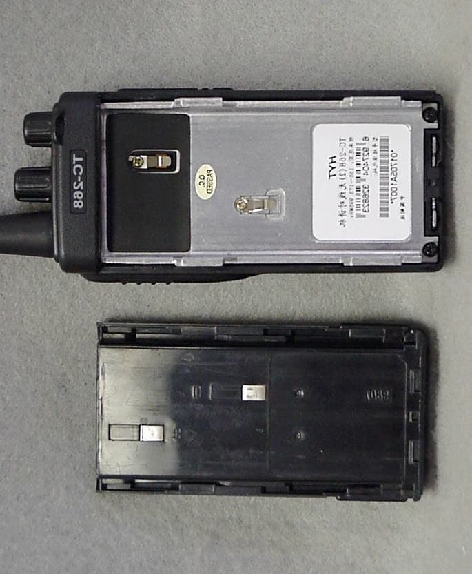
Click to zoom
Application Details
- Equipment Class
- TNF - Licensed Non-Broadcast Transmitter Held to Face
- Date of Grant
- Jan 03, 2002
- Application Purpose
- Original Equipment
- Date of Application
- Oct 22, 2001
- Equipment Note
- VHF FM Transceiver
- Frequency Range
- 150.00000000 - 174.00000000
- Company
- RELM Communications Inc
- Country
- United States
Documents & Files
Document Text
Text extracted from the exhibit documents filed with the FCC. Open a document above to read the original.
Users Manual
PRELIMINARY PRELIMINARY PRELIMINARY PRELIMINARY – –– – Owner’s Manual Owner’s ManualOwner’s Manual Owner’s Manual The following statement will be added here in the Owner’s Manual. FCC REQUIREMENTS FCC REQUIREMENTSFCC REQUIREMENTS FCC REQUIREMENTS The RPV516A portable radio must be properly licensed by the Federal Communications Commission (FCC) prior to use. Your local RELM dealer can assist you in meeting this requirement. PRELIMINARY PRELIMINARY PRELIMINARY PRELIMINARY – –– – Owner’s Manual Owner’s ManualOwner’s Manual Owner’s Manual PRELIMINARY PRELIMINARY PRELIMINARY PRELIMINARY – –– – Owner’s Manual Owner’s ManualOwner’s Manual Owner’s Manual PRELIMINARY PRELIMINARY PRELIMINARY PRELIMINARY – –– – Owner’s Manual Owner’s ManualOwner’s Manual Owner’s Manual PRELIMINARY PRELIMINARY PRELIMINARY PRELIMINARY – –– – Owner’s Manual Owner’s ManualOwner’s Manual Owner’s Manual PRELIMINARY PRELIMINARY PRELIMINARY PRELIMINARY – –– – Service ServiceService Service Manual Manual Manual Manual DR• CHKD• APPD• 24 Catalog CatalogCatalog Catalog General GeneralGeneral General P2 P2P2 P2 Specifications SpecificationsSpecifications Specifications P3 P3 P3 P3 Mode Combination P4 Mode Combination P4Mode Combination P4 Mode Combination P4 Circuit Description P5 Circuit Description P5Circuit Description P5 Circuit Description P5 Softwar SoftwarSoftwar Software Description e Descriptione Description e Description P10 P10 P10 P10 Test Description P15 Test Description P15Test Description P15 Test Description P15 RPV516A RPV516ARPV516A RPV516A Circuit Diagram Circuit Diagram Circuit Diagram Circuit Diagram RPV516A RPV516ARPV516A RPV516APCB Component Diagram PCB Component DiagramPCB Component Diagram PCB Component Diagram( (( (Two layers Mech 1 and Two layers Mech 1 and Two layers Mech 1 and Two layers Mech 1 and Mech 2 in PCB Mech 2 in PCBMech 2 in PCB Mech 2 in PCB) )) ) PRELIMINARY PRELIMINARY PRELIMINARY PRELIMINARY – –– – Service ServiceService Service Manual Manual Manual Manual DR• CHKD• APPD• 25 General GeneralGeneral General This manual is intended for use by experienced technicians familiar with similar types of commercial grade communications equipment. It contains main required service information and data for the equipment. The following precautions are recommended for personal safety: 1 . DO NOT transmit until all RF connectors are verified secure and any open connectors are properly terminated. 2. SHUT OFF and DO NOT operate this equipment near electrical blasting caps or in an explosive atmosphere. 3 . This equipment should be maintained by qualified technicians only. PRELIMINARY PRELIMINARY PRELIMINARY PRELIMINARY – –– – Service ServiceService Service Manual Manual Manual Manual DR• CHKD• APPD• 26 Main technical specifications General RPV516A(1) RPV516A(2) Frequency 136MHz~150MHz 150MHz~174MHz Channel 16 Channel space 25kHz / 12.5kHz Antenna impedance 50 • Transmitter impedance 2KΩ Input voltage 7.2V DC Frequency stability ±2.5×10 -6 TCXO 12.8MHz CPU clock Freq 7.3728MHz Transmitter Frequency stability ± 2.5 × 10 -6 Output power 4.0 ± 0.5W Operating sensitivity 12±4mV Audio distortion ≤5% Modulation limiting ≤5kHz / 2.5kHz Bandwidth ≤16 kHz/8kHz Modulate speciality ≤±3dB Spurious RF ≤7.5μW Adjacent power ≤-65 d B / -55dB Receiver Reference sensitivity Precede 0.28 • V / 0.35 • V Squelch turnon sensitivity ≤0.4 • V Audio frequency 500mW Audio deviation ≤7% Operating bandwidth ≥│ ± 7 kHz│/│ ± 3.5 kHz│ Audio response ≤+2dB -8dB First IF Freq 38.85MHz Second IF Freq 450kHz Channel restrain ≥-8 d B Obstruct ≥85d B Selectivity ≥65 d B / 60dB Spurious response ≥60 d B Intermodulation ≥60 d B PRELIMINARY PRELIMINARY PRELIMINARY PRELIMINARY – –– – Service ServiceService Service Manual Manual Manual Manual DR• CHKD• APPD• 27 Mode combination 1.Mode User mode: Turn on the power to enter. PC mode:Set and adjust with PC software or programmer. 2 . Parts description: •.Antenna •.C hannel (frequency) selector knob turn the knob to choose channel from 1~16•channel 16 may be set by distributor as scan channel•• •.LED light Lights red while transmitting, green while receiving a signal. Flashes red when the battery voltage is low, while transmitting. •.Power switch/Volume control Turn the knob clockwise to switch the transceiver ON, anti-clockwise to turn off the power till there is a “click” sound , rotate to adjust the volume level. (5)Speaker •. Microphone •.PTT•push to talk•switch Press the button while transmitting, and release it while receiving. •.Monitor key Press it to shut off squelch, noise could be heard, release to connect squelch. •.Speaker/microphone jack •.Belt clip •.Battery•TB-82• PRELIMINARY PRELIMINARY PRELIMINARY PRELIMINARY – –– – Service ServiceService Service Manual Manual Manual Manual DR• CHKD• APPD• 28 Circuit Description 3. Frequency configuration The receiver utilizes double conversion. The first IF is 38.85MHz and the second IF is 450KHZ. The first local oscillator signal is supplied from the PLL circuit. The PLL circuit in the transmitter generates the necessary frequencies. Fig.1 shows the frequencies. Fig1. Frequency configuration 4 . Receiver The receiver is double conversion superheterodyne, designed to operate in the frequency range of 150-174 MHz (M type), 136—— 150MHZ •M2 type •• 1 ) Front-end RF amplifier An incoming signal from the antenna is applied to an RF amplifier(Q203) after passing through a transmit/receive switch circuit(D 102 and D103 are off ) and a band pass filter(L208, L209 and L210). After the signal is amplified(Q203), the signal is filtered through a band pass filter (L203 and L214) to eliminate unwanted signals before it is passed to the first mixer. Band pass filters (L208, L209, L210, L203 and L214) have varactor diodes (D203, D204, D206, D202 and D201). The voltage of these diodes are controlled by to track the MPU (IC403) center frequency of the band pass filter. (See Fig. 2) PRELIMINARY PRELIMINARY PRELIMINARY PRELIMINARY – –– – Service ServiceService …
Text truncated - open the document above for the full version.
Users Manual
CELLTECH RESEARCH INC. Test Report S/N: 092601-169ARU 1955 Moss Court, Kelowna Date of Tests: October 16, 2001 B.C. Canada V1Y 9L3 FCC SAR Evaluation _________________________________________________________________________________________________________ © 2001 Celltech Research Inc. CERTIFICATE OF COMPLIANCE SAR EVALUATION This wireless portable device has been shown to be compliant for localized Specific Absorption Rate (SAR) for controlled environment/occupational exposure limits specified in ANSI/IEEE Std. C95.1-1992 and had been tested in accordance with the measurement procedures specified in ANSI/IEEE Std. C95.3-1999. I attest to the accuracy of data. All measurements were performed by me or were made under my supervision and are correct to the best of my knowledge and belief. I assume full responsibility for the completeness of these measurements and vouch for the qualifications of all persons taking them. Celltech Research Inc. certifies that no party to this application has been denied FCC benefits pursuant to Section 5301 of the Anti-Drug Abuse Act of 1988, 21 U.S.C. 853(a). Shawn McMillen General Manager Celltech Research Inc. Test Lab: CELLTECH RESEARCH INC. Testing and Engineering Lab 1955 Moss Court Kelowna, B.C. Canada V1Y 9L3 Phone: 250 - 860-3130 Fax: 250 - 860-3110 Toll Free: 1-877-545-6287 e-mail: [email protected] web site: www.celltechlabs.com Applicant Information: RELM WIRELESS CORPORATION 7100 Technology Drive West Melbourne, FL 32904 FCC Rule Part(s): 2.1093; ET Docket 96-326 FCC ID: ARURPV516A Model(s): RPV516A EUT Type: Portable VHF PTT Radio Transceiver Modulation: FM Tx Frequency Range: 150.05 - 173.95 MHz Conducted Power Tested: 5.3 Watts Antenna Type: Helical Whip Battery Type: 7.2VDC, 1100mAh, Ni-Cd Body-Worn Accessory: 1.4cm Belt-Clip CELLTECH RESEARCH INC. Test Report S/N: 092601-169ARU 1955 Moss Court, Kelowna Date of Tests: October 16, 2001 B.C. Canada V1Y 9L3 FCC SAR Evaluation _________________________________________________________________________________________________________ © 2001 Celltech Research Inc. TABLE OF CONTENTS 1.0 INTRODUCTION.................................................................. 1 2.0 DESCRIPTION OF EQUIPMENT UNDER TEST......................... 1 3.0 SAR MEASUREMENT SYSTEM ............................................. 2 4.0 SAR MEASUREMENT SUMMARY.......................................... 3-4 5.0 DETAILS OF SAR EVALUATION............................................ 5 6.0 EVALUATION PROCEDURES................................................. 5 7.0 SYSTEM VALIDATION.......................................................... 6 8.0 TISSUE PARAMETERS......................................................... 6 9.0 SIMULATED TISSUES........................................................... 7 10.0 SAR SAFETY LIMITS............................................................ 7 11.0 ROBOT SYSTEM SPECIFICATIONS........................................ 8 12.0 PROBE SPECIFICATION...................................................... 9 13.0 SAM PHANTOM.................................................................... 9 14.0 DEVICE HOLDER................................................................. 9 15.0 TEST EQUIPMENT LIST........................................................ 10 16.0 MEASUREMENT UNCERTAINTIES........................................ 11 17.0 REFERENCES...................................................................... 12 APPENDIX A - SAR MEASUREMENT DATA........................................ 13 APPENDIX B - DIPOLE VALIDATION................................................ 14 APPENDIX C - PROBE CALIBRATION............................................... 15 APPENDIX D – DETERMINATION OF PROBE CONVERSION FACTORS 16 APPENDIX E – SAR SENSITIVITIES................................................... 17 APPENDIX F - SAR TEST SETUP PHOTOGRAPHS............................... 18 CELLTECH RESEARCH INC. Test Report S/N: 092601-169ARU 1955 Moss Court, Kelowna Date of Tests: October 16, 2001 B.C. Canada V1Y 9L3 FCC SAR Evaluation _________________________________________________________________________________________________________ © 2001 Celltech Research Inc. RELM WIRELESS CORP. FCC ID: ARURPV516A 1 Portable VHF PTT Radio Transceiver (150-174MHz) 1.0 INTRODUCTION This measurement report shows compliance of the RELM WIRELESS CORP. Model: RPV516A Portable VHF PTT Radio Transceiver FCC ID: ARURPV516A with the regulations and procedures specified in FCC Part 2.1093, ET Docket 96-326 Rules (controlled exposure). The test procedures, as described in American National Standards Institute C95.1-1992 (1), and FCC OET Bulletin 65, Supplement C (Edition 01-01) (2) were employed. A description of the product and operating configuration, detailed summary of the test results, methodology and procedures used in the evaluation, equipment used, and the various provisions of the rules are included within this test report. 2.0 DESCRIPTION OF EQUIPMENT UNDER TEST (EUT) Rule Part(s) FCC 2.1093 ET Docket 96.326 Modulation FM EUT Type Portable VHF PTT Radio Transceiver Tx Frequency Range (MHz) 150.05 – 173.95 FCC ID ARURPV516A Conducted Power Tested 5.3 Watts Model No.(s) RPV516A Antenna Type(s) Helical Whip Serial No. Pre-production Power Supply Ni-Cd Battery (DC 7.2V 1100mAh) Front of EUT Back of EUT Left Side of EUT Right Side of EUT EUT with Speaker/Mic CELLTECH RESEARCH INC. Test Report S/N: 092601-169ARU 1955 Moss Court, Kelowna Date of Tests: October 16, 2001 B.C. Canada V1Y 9L3 FCC SAR Evaluation _________________________________________________________________________________________________________ © 2001 Celltech Research Inc. RELM WIRELESS CORP. FCC ID: ARURPV516A 2 Portable VHF PTT Radio Transceiver (150-174MHz) 3.0 SAR MEASUREMENT SYSTEM Celltech Research SAR measurement facility utilizes the Dosimetric Assessment System (DASY™) manufactured by Schmid & Partner Engineering AG (SPEAG™) of Zurich, Switzerland. The DASY syst…
Text truncated - open the document above for the full version.
Users Manual
ÞßÔ²ú TWO-WAY RADIO TM RPV516/RPU416 Owner's Manual RPV516/RPU416 Owner's Manual TM 1 OWNER’S MANUAL RELM Wireless Corporation Thank you! We are grateful that you choose RELM for your land mobile applications . We believe this easy- to-use transceiver will provide dependable communications to keep personnel operating at peak efficiency . Please read and understand this manual carefully for efficient operation. Applied model: RPV516: VHF FM Transceiver RPU416: UHF FM Transceiver 268ACManual.pm601-11-21, 11:061 RELM Wireless Corporation OWNER’S MANUAL Contents User Safety, Training, and General Information ...................... 1 Compliance with RF Energy Exposure Standards ................... 1 FCC Compliance ..................................................................... 3 Precautions............................................................................ 4 Preparations ........................................................................... 4 Supplied Accessories ............................................................... 5 Battery/Antenna and Other Accessories ............................ 5 Charging the Battery ................................................................ 5 Installing/Removing the Battery .............................................. 6 Installing the Antenna .............................................................. 7 Installing the Belt Clip ............................................................. 7 Installing the Additional Speaker/Microphone ........................ 7 Getting Acquainted ............................................................... 7 Basic Operation..................................................................... 8 Auxiliary Functions.............................................................. 9 Time-out Timer ....................................................................... 9 Battery Save ............................................................................ 9 Low Battery Warning ............................................................ 10 Monitor................................................................................. 10 CTCSS/DCS.......................................................................... 10 Two Tone Signaling ................................................................ 10 Channel Scan.......................................................................... 12 Busy Channel Lockout .......................................................... 12 Optional Accessories.......................................................... 13 Troubleshooting.................................................................. 13 Frequency Chart ................................................................ 14 268ACManual.pm601-11-21, 11:062 OWNER’S MANUAL RELM Wireless Corporation User Safety, Training, and General Information READ THIS IMPORTANT INFORMATION ON SAFE AND EFFICIENT OPERATION BEFORE USING YOUR RELM HANDHELD PORTABLE TWO-WAY RADIO. Compliance with RF Energy Exposure Standards Your RELM two-way radio is designed and tested to comply with a number of national and international standards and guidelines (listed below) regarding human exposure to radio frequency electromag- netic energy. This radio complies with the IEEE (FCC) and ICNIRP exposure limits for occupational/controlled RF exposure environ- ment at duty cycles of up to 50% talk-50% listen and should be used for occupational use only. In terms of measuring RF energy for compliance with the FCC exposure guidelines, your radio radiates measurable RF energy only while it is transmitting (during talking), not when it is receiving (listening) or in standby mode. Note:The approved batteries supplied with this radio are rated for a 5-5-90 duty cycle (5% talk-5% listen-90% standby), even though this radio complies with the FCC occupational RF exposure limits at duty cycles of up to 50% talk. Your RELM two-way radio complies with the following of RF energy exposure standards and guidelines: •United States Federal Communications Commission, Code of Federal Regulations; 47CFR part 2 sub-part J •American National Standards Institute (ANS)/Institute of Electrical and Electronic Engineers (IEEE) C95. 1-1992 •Institute of Electrical and Electronic Engineers (IEEE) C95. 1- 1999 Edition •International Commission on Non-Ionizing Radiation Protection (ICNIRP) 1998 268ACManual.pm601-11-21, 11:063 RELM Wireless Corporation OWNER’S MANUAL •Ministry of Health (Canada) Safety Code 6. Limits of Human Exposure to Radiofrequency Electromagnetic Fields in the Frequency Range from 3kHz to 300GHz, 1999 •Australian Communications Authority Radiocommunications (Electromagnetic Radiation-Human Exposure) Standard 1999 (applicable to wireless phones only) Operational Instructions and Training Guidelines To ensure optimal performance and compliance with the occupa- tional/controlled environment RF energy exposure limits in the above standards and guidelines, users should transmit no more than 50% of the time and always adhere to the following procedures: Transmit and Receive To transmit (talk), push the Push-To-Talk (PTT) button; to re- ceive, release the PTT button. Hand-held radio operation Hold the radio in a vertical position with the microphone one to two inches (2.5 to 5 cm) away from the lips. Body-worn operation •Always place the radio in a RELM approved clip, holder, hol- ster, case, or body harness for this product. Use of non-RELM- approved accessories may exceed FCC RF exposure guidelines. •If you do not use a RELM approved body-worn accessory and are not using the radio in the intended use position in front of the face, then ensure the antenna and the radio are kept 2.5 cm (one inch) from the body when transmitting. Antennas & Batteries •Use only RELM approved, supplied antenna or RELM approved replacement antenna. Unauthorized antennas; modifications, or attachments could damage the radio and may violate FCC regulations. 268ACManual.pm601-11-2…
Text truncated - open the document above for the full version.
Block Diagram
Functional Block Diagrams & Circuits Description Functional Block Diagrams & Circuits Description Functional Block Diagrams & Circuits Description Functional Block Diagrams & Circuits Description 01.07.11 1 A Date Sheet VER APPD: CHKD: DR : TC26805-01A File: CO.,LTD SHENZHEN HYT SCIENCE&TECHNOLOGY HYT GLED RLED REF 5RC HG-KD S-81350 IC404 MIC500 2SC4919 Q503 AGC/MUTE DAN222 D501SW MUTE 1SS372 D500DET LIMITER AMP HPF2100VNJMIC500 5MS 143ZE DTA Q504 RX 5MS 2SK1824 Q500 WNTC WIDE/NARROW 5T 2SC4617 Q502LPF LPF 2SC4617 Q501 5T DQT BALANCE VR500 DEV VR501 TO DEV TIBITI WNRC 144EE DTAQ303 WIDE/NARROW SW POWER SW 1SR154 D502 PROTECTION REVERSE B SB AFCO DTC 144EE Q304 SW 144EE DTC Q306 SW 2SA1362 Q305 B SW MUTE 2SK1824 Q302 MUTE SW VOLUME TA7368F IC302 AUDIO SW 3SK286 Q307 MUTE SW SP B SW SW 5T SW 5R 3SK228 Q202 1ST MIXER 38.85MHz XF201 MCF 2SC4649 Q201 IF AMP 5R 114EE DTAQ200 CHARGE BUSY 5R 38.4MHz 2SC4649 Q1 *3 2ND LOCAL AMP 5R TCXO 114EE DTC Q403 AMP 2SC5108 Q2 12.8MHz 3C TCXO LOOP FILTER F.CONT *2 MA2S376 D1.D3 RX VCO NV 2SK508 Q3 RX UMC4 2SJ243 Q5.Q7 T/R SW 5C MA2S111 2SC4617 Q8 . D6 RIPPLE FILTER DEV LO SW 2SC5108 BATT BPF D203 L203.L204.L214 TUNE TUNE AMP 5R 3SK286 Q203 D201.D202L210.L211L208.L209 BPF ANT SW *2 HSC277 D103D102 B PROTECTION THERMAL 114TE DTC Q110 5T 5T APC PABC 2SK1824 FMMT717 Q103Q104 114EE DTCQ108 2SK1824 Q106 114EE DTA Q109 NJM2904 IC100 SW APC *2 MA2S376 D2.D4 F.CONT MA360 D5 2SC4226 Q4 TX VCO 2SC5108 Q6 BUFF AMP 5C 2SC5108 Q100 AMP 5T 5C 5T *2 HSC277 D200D100 AMPQ101 2SK2596 Q102 2SK2595 Q105 HVU131 D101 ANT DRIVE AMP FINAL AMP ANT SW LPF DET COIL L212 CF CF200 450kHz IF IC TA31136FN IC200 IC301 LIMITER DA221 BASE BAND SECTION 5R 5MS LPF LPF NJM2904V 5R 5MS LPF IC300 FLAT AMP HPFHPF NJM2902V DEV 5411A/B X1 TO VCCN VR1 2ND LOCAL 5C UL CKDTEP PLL DATA PLL IC MB1511 IC1 SHIFT CLOCK 7.3728MHz X400 MONI S403 PTTS402 TX/BUSY LAMP SB D400 D401 SW SW 123JEDTA Q408 SW 5M 5V REG 5R 5TC SAVE B 672TUPAQ405 *2 UMG3N FP210Q407 Q404Q406 5T.5C.REG 5C 5T SB 114EEDTCQ401 114EE DTC Q400 5MC SW 114YE DTA Q402 5M INT RESET 9140NR PSTIC400 45C RN5VLIC402 SDASCL 5M 2.5 N1OSI AT2408 IC401 EEPROM 3 2 1 ENC 0 CHANNEL SW BUSYTIBI TI UL BATT TXD RXD READ/WRITE SHIFT VCCN RXGLED BEEPPABC RLEDWNTC CK5TC DT5MC EPSAVE MUTETO AFCOWNRC 5RCAPC/TUNE M38034 IC403 Title:TC268È¡\U+2514Ý\U+2510\U+2017\U+2550\U+255D ABCD 1 2 3 4 5 6 DC BA 6 5 4 3 2 1
Cover Letter(s)
FCC ID: ARURPV516A
Cover Letter(s)
Response for Request for information (request sent 12/12/01) for Re: FCC ID ARURPV516A Applicant:RELM Communications Inc Correspondence Reference Number: 21473 731 Confirmation Number: EA811923 1.) Please provide justification for Section 22. Relm is requesting Part 22 Certification to be consistent with other similar products of theirs that they have certified over the years. For these types of products for Relm/BK Radio (Both Relm and BK Radio are related companies), they have always certified under Parts 22, 74, 80, and 90. One recent projects certified was under FCC ID: K95GPH51. This product is similar to the unit currently being certified. 2.) Provide a list of Channel Numbers and the corresponding Channel Frequencies that the device is capable of using under US operation? This should be a comprehensive list and may have to be furnished by the manufacturer. Section 80.203. The RPV516A operates from 150 to 174 MHz and in 2.5 kHz and 6.25 kHz steps. See uploaded files for possible operating frequencies 3.) Please indicate compliance with Section 90.203, programming requirements. The end user cannot alter the frequencies or place the unit in program mode. The factory and authorized dealers can alter (program) frequencies by one of three ways: a. Using a PC and editor software. b. Cloning from radio to radio through a cloning cable. c. External hand held programmer that plugs into the side port of the unit. 4.) Please provide frequency stability for battery end-point. An updated Frequency Stability file was submitted on October 26, 2001. The manufacturer considers 6.0 VDC to be the end point of the battery. 5) Which band did you submit, narrow or wide for Transient Frequency Behavior. Please submit Section 90.214 data for both deviation levels. We have resubmitted data for both. Please see revised data. 6) The Audio Response plots you have submitted, on pages 22 and 23 of test report is not acceptable. Please send plots showing per Section 2.1047(a). We have resubmitted data. Please see revised data. 7) Please submit low pass filter response per Section 2.1047(a). We have resubmitted data. Please see revised data. 8.) Probe conversion factors used for muscle tissue SAR measurements. Certified conversion factors were only found for head simulating liquid in the posted exhibits. Please also provide a statement justifying any cases where the probe calibration was performed at different frequencies and with different tissue parameters than used for testing. Please include an analysis of the expected variation on the SAR value. Alternatively please provide new SAR data using a probe calibrated at corresponding test frequencies and with test tissue dielectric parameters See updated SAR files 9.) Provide attestation statement that liquid depth was at least 15 cm for all tests. If available please provide Z-axis scan SAR data for the highest SAR test points. See updated SAR files 10.) Recalculated SAR values and SAR plots for all test points using measured liquid parameters if possible without additional testing. Targets parameters were apparently used as noted on the provided SAR plots. If not possible please provide analysis showing the expected effects on the SAR values if the measured parameters had been used. See updated SAR files 11.) Revised user manual to include warning/cautions statements (not "Important Information.....") to alert users that this device is not approved for use by the general population as it only meets the higher exposure limit for occupational use. It should clearly indicate that these specific requirements are for meeting FCC RF exposure compliance, therefore, it is not optional. The device is approved to operate in typical PTT mode not exceeding a 50% duty factor, as it would not comply with RF exposure limits at higher duty factors. The specific body-worn operating requirements, as tested, must be described to users for satisfying compliance. Other body-worn operating conditions that have not been tested are not approved for use with this device as they may not comply and should be avoided. It should also clearly state that users are required to have appropriate training to control their exposure condition and duration to satisfy the higher occupational exposure limit be! fore using this device. The EUT met with general/uncontrolled limits with 100% duty cycle. Please see updated SAR files for further information. We have provided an updated manual since the original one was preliminary. 12.) A warning label for attachment to the exterior of the radio clearly warning any user of a radiation hazard and referring the user to the related operation training section in the manual. The manufacturer would like to know if this still necessary since the EUT meet with general/uncontrolled limits with 100% duty cycle as given in the SAR information. if it is still required, must this label be a permanent style label, or may this be a removable label from user once the unit is opened or used? 13.) Please confirm weather or not there are other antennas used for this device. No, there are no other antennas being used.
Cover Letter(s)
Response for Request for information (request sent 12/28/01) for Re: FCC ID ARURPV516A Applicant:RELM Communications Inc Correspondence Reference Number: 21597 731 Confirmation Number: EA811923 1) Your list on 12/26/01 indicates that this device operates on Marine Frequencies of 156.10 MHz channel 02, 156.20 MHz channel 04 and 04A, 156.025 MHz channel 60, 156.125 MHz channel 62. It is forbidden to transmit on these frequencies for Marine Part 80 operation. Please explain. The unit is dealer or factory programmable and the dealer or factory is going to program only the frequencies that the end user has license for. 2) Exhibit 8 Revised Manual 121901 uploaded on 12/27/01 is a SAR report. Your reply question 11 on 12/27/01 states we have provided an updated manual since the original one was preliminary. Please submit a revised Users Manual. This has been uploaded again. Additional Note: Celltech discovered a few errors in revised test reports for RF Exposure. I have provide the most recent version of these files as well.
External Photos
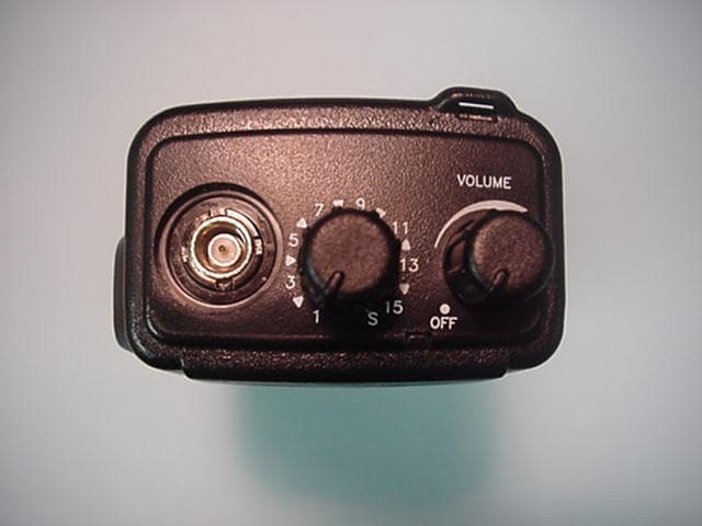
FCC ID: ARURPV516A Photo 1.EUT, Front View FCC ID: ARURPV516A Photo 2.EUT, Rear View FCC ID: ARURPV516A Photo 3.EUT, Left Side FCC ID: ARURPV516A Photo 4.EUT, Right Side FCC ID: ARURPV516A Photo 5.EUT, Battery Removed FCC ID: ARURPV516A Photo 6. EUT, Top View
ID Label/Location Info
FCC ID: ARURPV516A FCC ID: ARURPV516A
Internal Photos
FCC ID: ARURPV516A Photo 7.EUT, Bottom Side of Main Board FCC ID: ARURPV516A Photo 8.EUT, Top Side, Showing Shield Removed FCC ID: ARURPV516A Photo 9.EUT, Top Side of Main Board
Operational Description
FCC ID: ARURPV516A 1.2Related Submittal(s)/Grant(s) The EUT will be used with part of a system to send/receive data. The transceiver presented in this report will be used with other like transceivers. The EUT is subject to the following authorizations: a)Certification as a transmitter as specified by Parts 22, 74, 80, and 90. The information contained in this report is presented for the certification authorization(s) for the EUT. Information Required Calculate Necessary Bandwidth Wide Band:Narrow Band M = 3000M= 3000 D = 5000D= 2500 K = 1.0 from table III-AK = 1.0 from table III-A 2M + 2DK = 16,0002M + 2DK = 11,000
Operational Description
FCC ID: ARURPV516A GENERAL INFORMATION 1.1Product Description The Equipment Under Test (EUT) is a RELM Wireless Corporation, Model RPV516A. The EUT is a VHF FM Portable transceiver which operates on 16 programmable channels (25 kHz and/or 12.5 kHz) within the 150.0 to 174.0 MHz range. The unit is manufactured by the following company: Shenzhen HYT Science & Technology Co., Ltd. R2-A 1/F Shenzhen High-Tech Industrial Park Shennan Road Shenzhen China Postcode: 518057 Information Required Calculate Necessary Bandwidth Wide Band:Narrow Band M = 3000M= 3000 D = 5000D= 2500 K = 1.0 from table III-AK = 1.0 from table III-A 2M + 2DK = 16,0002M + 2DK = 11,000
Parts List/Tune Up Info
FCC ID: ARURPV516A FCC ID: ARURPV516A FCC ID: ARURPV516A FCC ID: ARURPV516A FCC ID: ARURPV516A FCC ID: ARURPV516A
RF Exposure Info
CELLTECH RESEARCH INC. Test Report S/N: 092601-169ARU 1955 Moss Court, Kelowna Date of Tests: October 16, 2001 B.C. Canada V1Y 9L3 FCC SAR Evaluation _________________________________________________________________________________________________________ © 2001 Celltech Research Inc. CERTIFICATE OF COMPLIANCE SAR EVALUATION This wireless portable device has been shown to be compliant for localized Specific Absorption Rate (SAR) for controlled environment/occupational exposure limits specified in ANSI/IEEE Std. C95.1-1992 and had been tested in accordance with the measurement procedures specified in ANSI/IEEE Std. C95.3-1999. I attest to the accuracy of data. All measurements were performed by me or were made under my supervision and are correct to the best of my knowledge and belief. I assume full responsibility for the completeness of these measurements and vouch for the qualifications of all persons taking them. Celltech Research Inc. certifies that no party to this application has been denied FCC benefits pursuant to Section 5301 of the Anti-Drug Abuse Act of 1988, 21 U.S.C. 853(a). Shawn McMillen General Manager Celltech Research Inc. Test Lab: CELLTECH RESEARCH INC. Testing and Engineering Lab 1955 Moss Court Kelowna, B.C. Canada V1Y 9L3 Phone: 250 - 860-3130 Fax: 250 - 860-3110 Toll Free: 1-877-545-6287 e-mail: [email protected] web site: www.celltechlabs.com Applicant Information: RELM WIRELESS CORPORATION 7100 Technology Drive West Melbourne, FL 32904 FCC Rule Part(s): 2.1093; ET Docket 96-326 FCC ID: ARURPV516A Model(s): RPV516A EUT Type: Portable…
Text truncated - open the document above for the full version.
Contact Information
Applicant
Walter C. Simciak(Engineering Manager)
Technical Contact
U.S. TechnologiesTimothy R Johnson
[email protected]770-740-0717
3505 Francis Circle · Alpharetta, Georgia · United States
Non-Technical Contact
U.S. TechnologiesTimothy R Johnson
[email protected]770-740-0717
Test Firm
US TechSandy McEnery
Technical Specifications
| # | Rule Parts | Frequency Range | Power Output | Emission | Tolerance |
|---|---|---|---|---|---|
| 2 | 22,74,80,9 | 150 MHz - 174 MHz | 5.3 W | 11K0F3E | 1.1 ppm |
Other Applications from RELM Communications Inc
ARURPU416B
Dec 15, 2004UHF Transceiver
Equipment Class
TNF - Licensed Non-Broadcast Transmitter Held to Face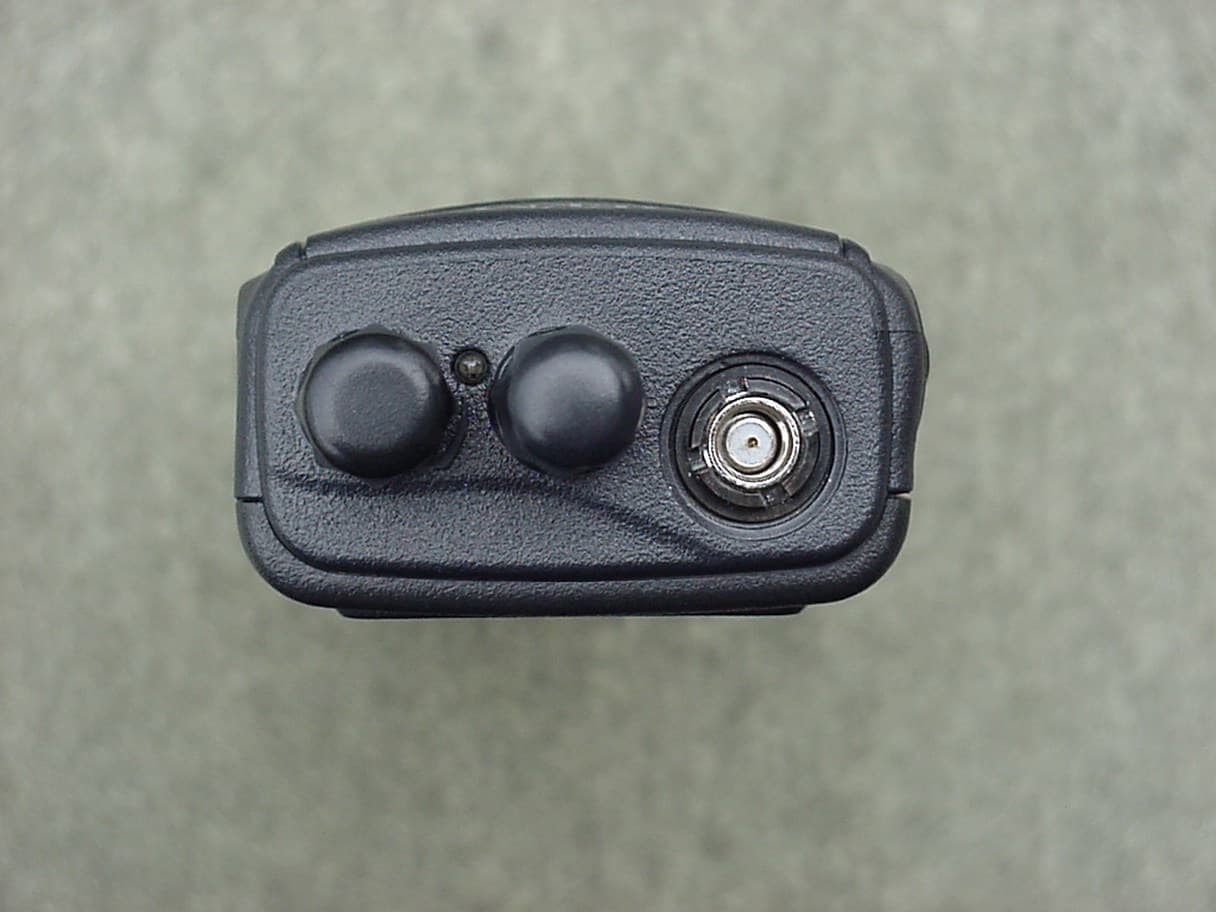
ARURPU499A
Apr 25, 2004UHF Land Mobile Radio
Equipment Class
TNF - Licensed Non-Broadcast Transmitter Held to Face
ARURPV599A
Dec 22, 2002VHF FM Transceiver
Equipment Class
TNF - Licensed Non-Broadcast Transmitter Held to Face
ARUSRU50ABC
Jan 25, 1999Repeater
Equipment Class
TNB - Licensed Non-Broadcast Station Transmitter
ARUSRE35AB
Oct 06, 1998TNB - Licensed Non-Broadcast Station Transmitter
Equipment Class
TNB - Licensed Non-Broadcast Station Transmitter