ARUSRU50ABCRepeater
RELM Communications Inc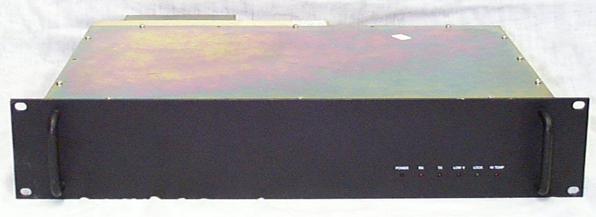
Click to zoom
Application Details
- Equipment Class
- TNB - Licensed Non-Broadcast Station Transmitter
- Date of Grant
- Jan 25, 1999
- Application Purpose
- Original Equipment
- Date of Application
- Oct 05, 1998
- Equipment Note
- Repeater
- Frequency Range
- 485.00000000 - 520.00000000
- Company
- RELM Communications Inc
- Country
- United States
Documents & Files
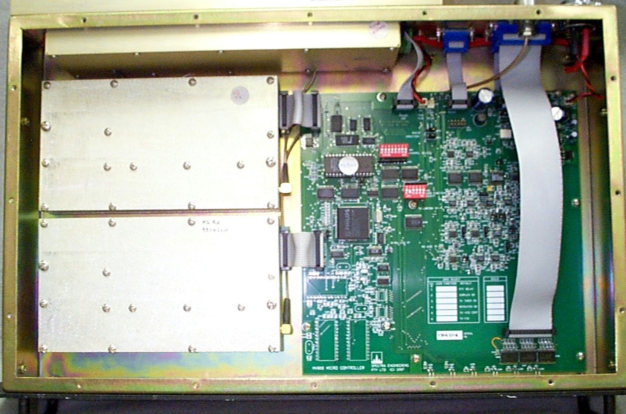

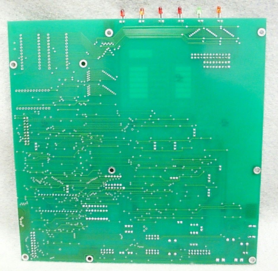
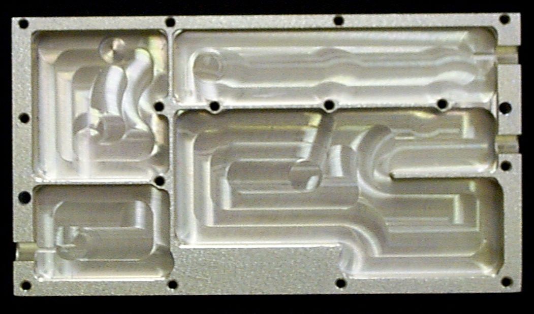
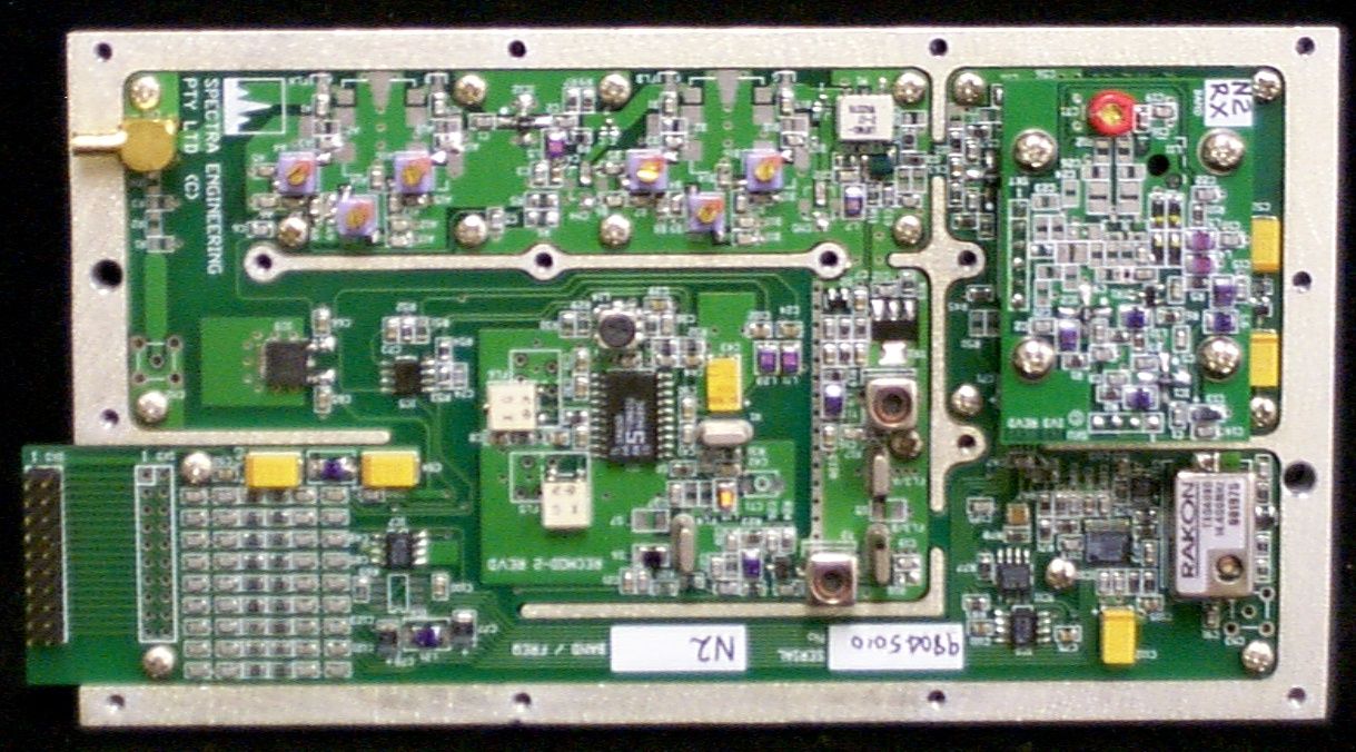
Document Text
Text extracted from the exhibit documents filed with the FCC. Open a document above to read the original.
Users Manual
1/98 RELM Communications, Inc SR35/50 RF Transceiver/Repeater USER MANUAL RELM Communications, Inc 7505 Technology Drive W. Melbourne, Florida 32904 Voice: 407- 984-1414 Fax: 407-984-0434 S Series Repeater USER MANUAL ©RELM Communications Inc. Revision 1.0 2 Manual Revision 1.0 January 1998 Applicable reference: Micro Controller Board Rev C In order to continually improve our products, RELM Communications, Inc reserves the right to alter, without notice and at any time, the equipment and specifications described in this document. All performance figures quoted are typical and are subject to normal manufacturing and service tolerances. The purchaser is warned that statements made in this document may be inaccurate due to typographical or other errors or subsequent modifications of the product. While every care has been taken in the creation of this document, no warranty of accuracy or reliability is given in any advice or information contained in this document. The responsibility for any loss or damage whatsoever arising in any way or any representation, act or omission whether express or implied (including responsibility to any person by reason of negligence) is not accepted by RELM Communications, Inc or any officer, agent or employee of RELM Communications Inc. Copyright © RELM Communications, Inc. S Series Repeater USER MANUAL ©RELM Communications Inc. Revision 1.0 3 Record Of Changes Any changes to this manual are recorded on this list. DateManual VersionChapter ChangesPages Changed Jan 19981.0All - Initial ReleaseAll S Series Repeater USER MANUAL ©RELM Communications Inc. Revision 1.0 4 SAFETY SUMMARY Although there are no dangerous mains voltages present within the equipment, the following general safety precautions as would normally apply, should be observed during all phases of operation, service and repair of this equipment. AROUND THE EQUIPMENT. To minimize any possible shock hazard from an external power supply or lightning strike, the chassis or equipment cabinet must be connected to an electrical ground. Provide adequate ventilation around the rear of the equipment. DO NOT OPERATE IN AN EXPLOSIVE ATMOSPHERE. Do not operate the equipment in the presence of flammable gases or fumes. Operation of any electrical equipment in such an environment constitutes a definite safety hazard. DO NOT ATTEMPT INTERNAL SERVICE WHILE TRANSMITTING. Thermal or RF burns may result from touching certain components within the power amplifier module while transmitting or operating the transmitter. DO NOT SUBSTITUTE PARTS OR MODIFY THE EQUIPMENT. Because of the danger of introducing additional hazards, do not install substitute or lower voltage parts to the equipment. Return to your authorized distributor. EXERCISE CAUTION AND CORRECT DISPOSAL OF RF POWER DEVICES. Most RF power transistors and some RF power hybrids contain Beryllium Oxide. Although they are normally safe, if physically damaged toxic dust may be released. Consult your local authority for correct disposal thereof. S Series Repeater USER MANUAL ©RELM Communications Inc. Revision 1.0 5 Contents CONTENTS........................................................................................................................................................... 5 INTRODUCTION................................................................................................................................................. 7 G ENERAL DESCRIPTION........................................................................................................................................... 7 Exciter Module Description .............................................................................................................................. 7 Receiver Module Description ............................................................................................................................ 8 Power Amplifier Module Description................................................................................................................ 8 K EY FEATURES AND ADVANTAGES.......................................................................................................................... 8 I NDICATORS AND CONNECTORS...............................................................................................................................9 Standard Version front panel ............................................................................................................................ 9 OEM Version front panel .................................................................................................................................. 9 Rear Panel Connectors ................................................................................................................................... 11 R EAR VIEW SR35/50.............................................................................................................................................. 11 S IDE VIEW SR35/50 ............................................................................................................................................... 12 INSTALLATION ................................................................................................................................................ 12 TECHNICAL DESCRIPTION .......................................................................................................................... 13 I NTERNAL CONNECTIONS....................................................................................................................................... 13 E XCITER MODULE TECHNICAL DESCRIPTION......................................................................................................... 14 R ECEIVER MODULE TECHNICAL DESCRIPTION...................................................................................................... 14 PA M ODULE TECHNICAL DESCRIPTION....................................................…
Text truncated - open the document above for the full version.
Users Manual
1/98 RELM Communications, Inc SR35/50 RF Transceiver/Repeater USER MANUAL RELM Communications, Inc 7505 Technology Drive W. Melbourne, Florida 32904 Voice: 407- 984-1414 Fax: 407-984-0434 S Series Repeater USER MANUAL ©RELM Communications Inc. Revision 1.0 2 Manual Revision 1.0 January 1998 Applicable reference: Micro Controller Board Rev C In order to continually improve our products, RELM Communications, Inc reserves the right to alter, without notice and at any time, the equipment and specifications described in this document. All performance figures quoted are typical and are subject to normal manufacturing and service tolerances. The purchaser is warned that statements made in this document may be inaccurate due to typographical or other errors or subsequent modifications of the product. While every care has been taken in the creation of this document, no warranty of accuracy or reliability is given in any advice or information contained in this document. The responsibility for any loss or damage whatsoever arising in any way or any representation, act or omission whether express or implied (including responsibility to any person by reason of negligence) is not accepted by RELM Communications, Inc or any officer, agent or employee of RELM Communications Inc. Copyright © RELM Communications, Inc. S Series Repeater USER MANUAL ©RELM Communications Inc. Revision 1.0 3 Record Of Changes Any changes to this manual are recorded on this list. DateManual VersionChapter ChangesPages Changed Jan 19981.0All - Initial ReleaseAll S Series Repeater USER MANUAL ©RELM Communications Inc. Revision 1.0 4 SAFETY SUMMARY Although there are no dangerous mains voltages present within the equipment, the following general safety precautions as would normally apply, should be observed during all phases of operation, service and repair of this equipment. AROUND THE EQUIPMENT. To minimize any possible shock hazard from an external power supply or lightning strike, the chassis or equipment cabinet must be connected to an electrical ground. Provide adequate ventilation around the rear of the equipment. DO NOT OPERATE IN AN EXPLOSIVE ATMOSPHERE. Do not operate the equipment in the presence of flammable gases or fumes. Operation of any electrical equipment in such an environment constitutes a definite safety hazard. DO NOT ATTEMPT INTERNAL SERVICE WHILE TRANSMITTING. Thermal or RF burns may result from touching certain components within the power amplifier module while transmitting or operating the transmitter. DO NOT SUBSTITUTE PARTS OR MODIFY THE EQUIPMENT. Because of the danger of introducing additional hazards, do not install substitute or lower voltage parts to the equipment. Return to your authorized distributor. EXERCISE CAUTION AND CORRECT DISPOSAL OF RF POWER DEVICES. Most RF power transistors and some RF power hybrids contain Beryllium Oxide. Although they are normally safe, if physically damaged toxic dust may be released. Consult your local authority for correct disposal thereof. S Series Repeater USER MANUAL ©RELM Communications Inc. Revision 1.0 5 Contents CONTENTS........................................................................................................................................................... 5 INTRODUCTION................................................................................................................................................. 7 G ENERAL D ESCRIPTION ........................................................................................................................................... 7 Exciter Module Description .............................................................................................................................. 7 Receiver Module Description ............................................................................................................................ 8 Power Amplifier Module Description................................................................................................................ 8 K EY F EATURES AND A DVANTAGES .......................................................................................................................... 8 I NDICATORS AND C ONNECTORS ...............................................................................................................................9 Standard Version front panel ............................................................................................................................ 9 OEM Version front panel .................................................................................................................................. 9 Rear Panel Connectors ................................................................................................................................... 11 R EAR VIEW SR35/50.............................................................................................................................................. 11 S IDE VIEW SR35/50 ............................................................................................................................................... 12 INSTALLATION ................................................................................................................................................ 12 TECHNICAL DESCRIPTION .......................................................................................................................... 13 I NTERNAL C ONNECTIONS ....................................................................................................................................... 13 E XCITER M ODULE T ECHNICAL D ESCRIPTION ......................................................................................................... 14 R ECEIVER M ODULE T ECHNICAL D ESCRIPTION ...................................................................................................... 14 PA M ODULE T ECHNICAL D ESCRIPTION ................................…
Text truncated - open the document above for the full version.
ID Label/Location Info
Label master drawing for the following units... FCCIDBandModel ARUSRV50A135 to 160 MHzSRV50A ARUSRV50B148 to 174 MHzSRV50B ARUSRU50ABC400 to 435 MHzSRU50A ARUSRU50ABC450 to 485 MHzSRU50B ARUSRU50ABC485 to 520 MHzSRU50C ARUSRE35ABTx 805 to 825 MHzSRE35AB Rx 850 to 870 MHz Note: UHF is being combined into ARUSRU50ABC which will be used for both 5 kHz and 2.5 kHz deviation systems (25 kHz and 12.5 kHz channels). FCCID: ARUSRU50ABC 450 to 485 MHz Transceiver Model: SRU50B Canada: RELM Communications, Inc W. Melbourne, FL 32904 Made in Australia FCCID: ARUSRU50ABC 485 to 520 MHz Transceiver Model: SRU50C Canada: RELM Communications, Inc W. Melbourne, FL 32904 Made in Australia
Test Report
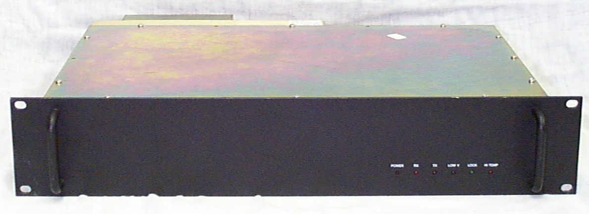
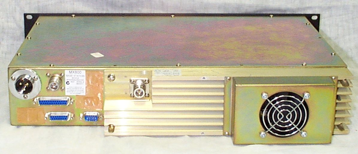
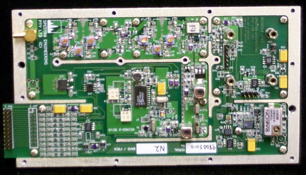
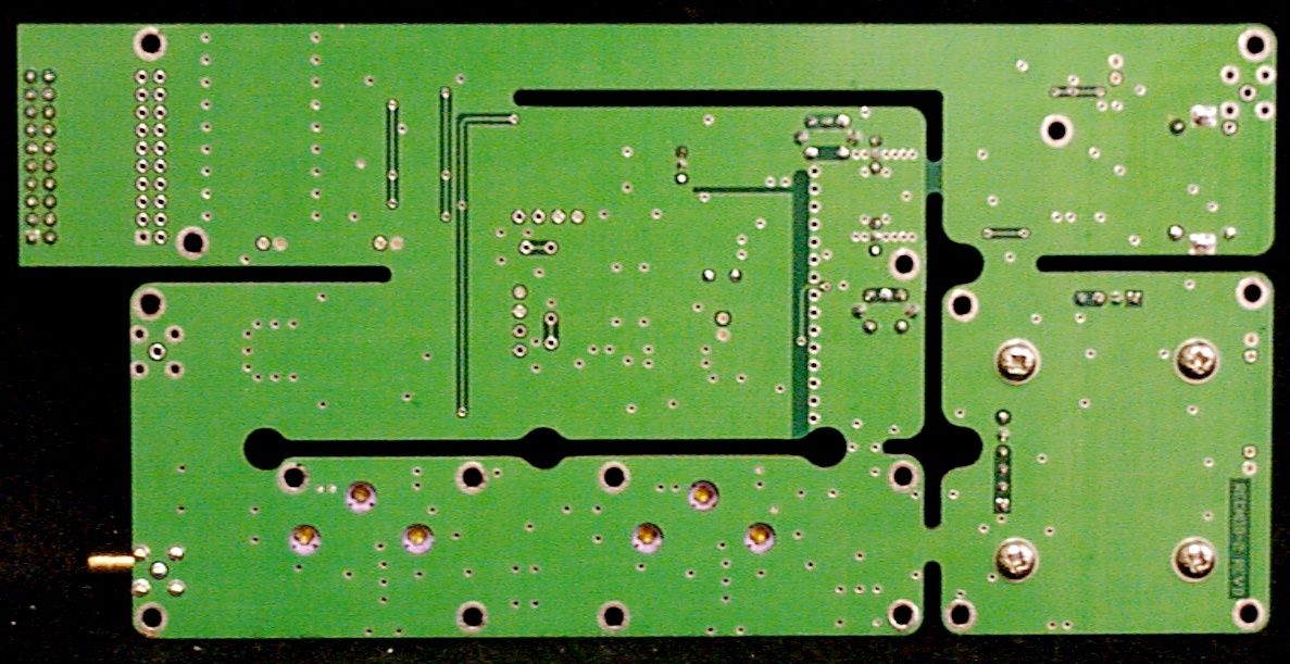
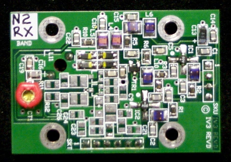
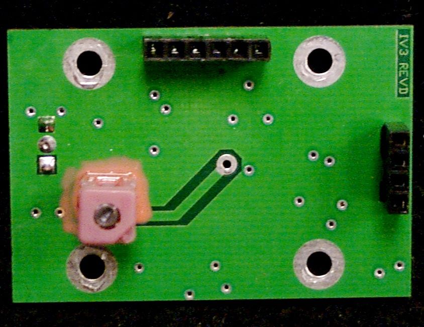
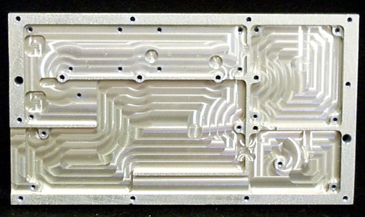
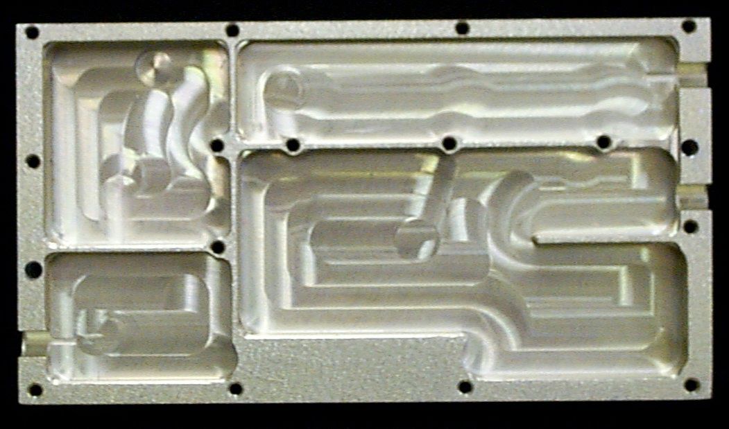
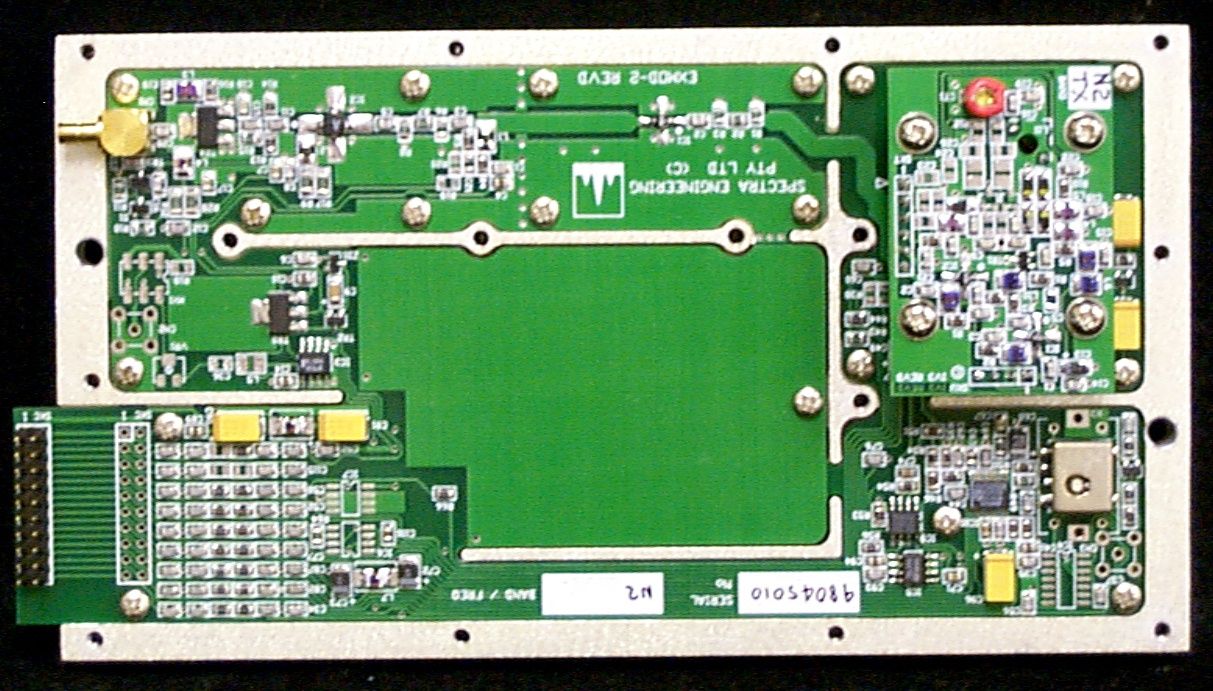
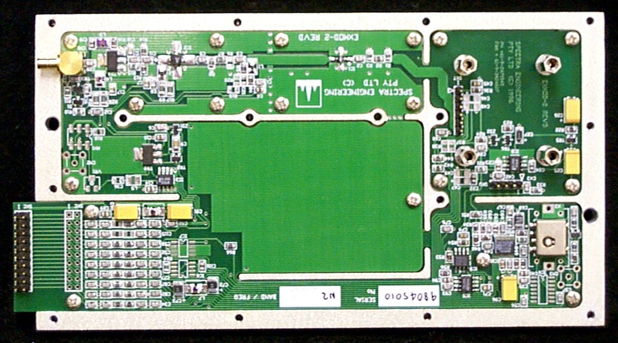
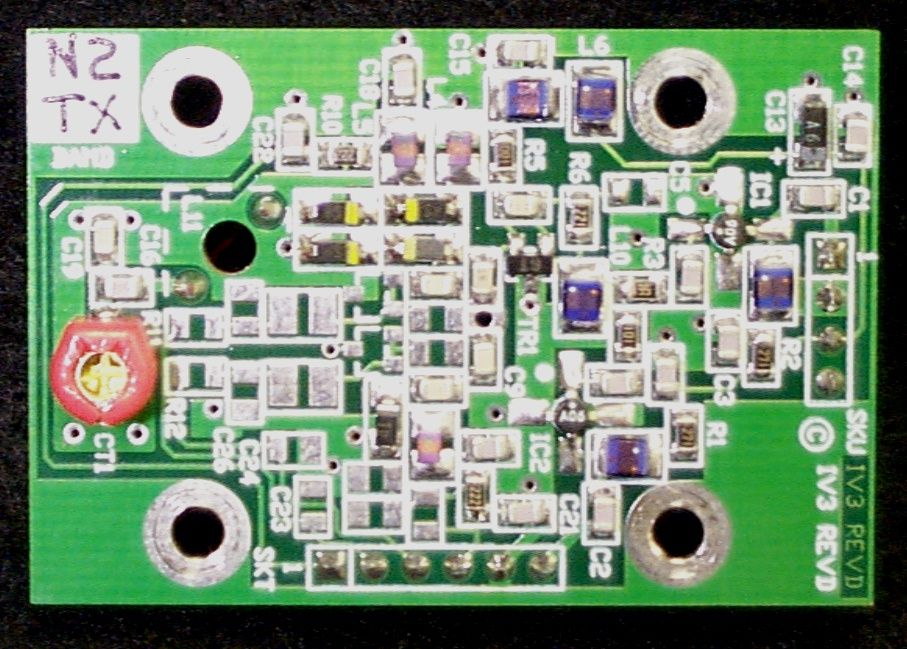
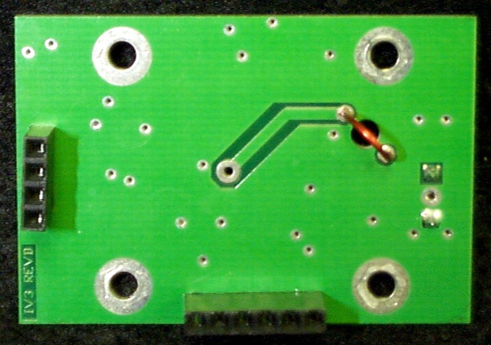
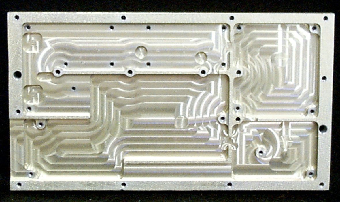
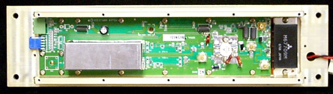
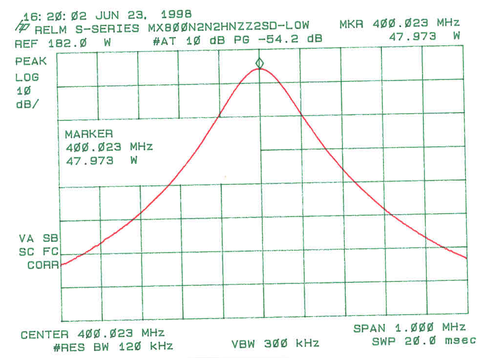
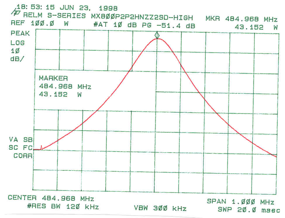
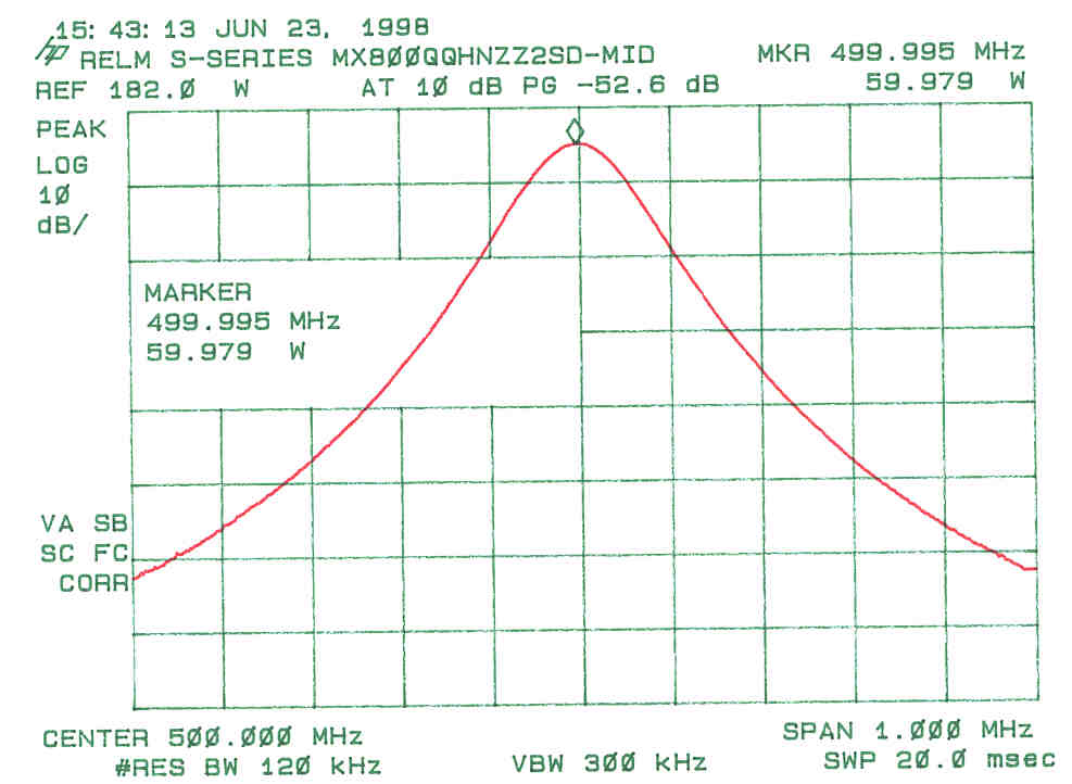
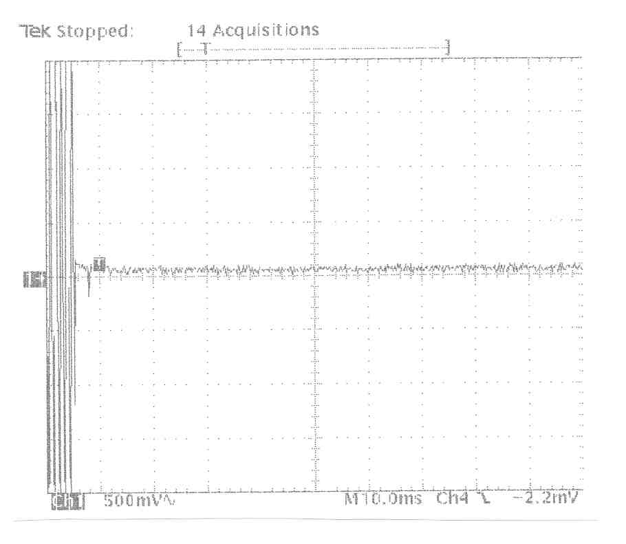
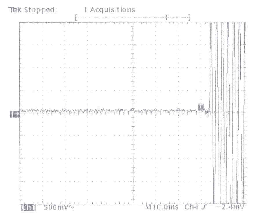
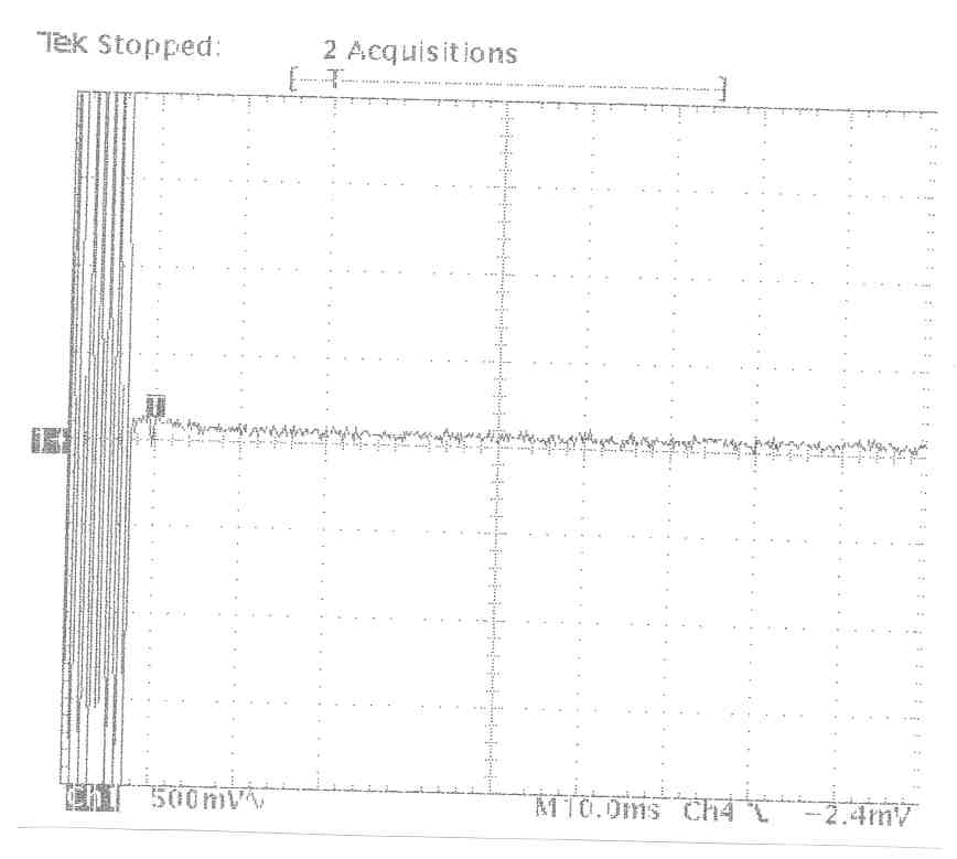
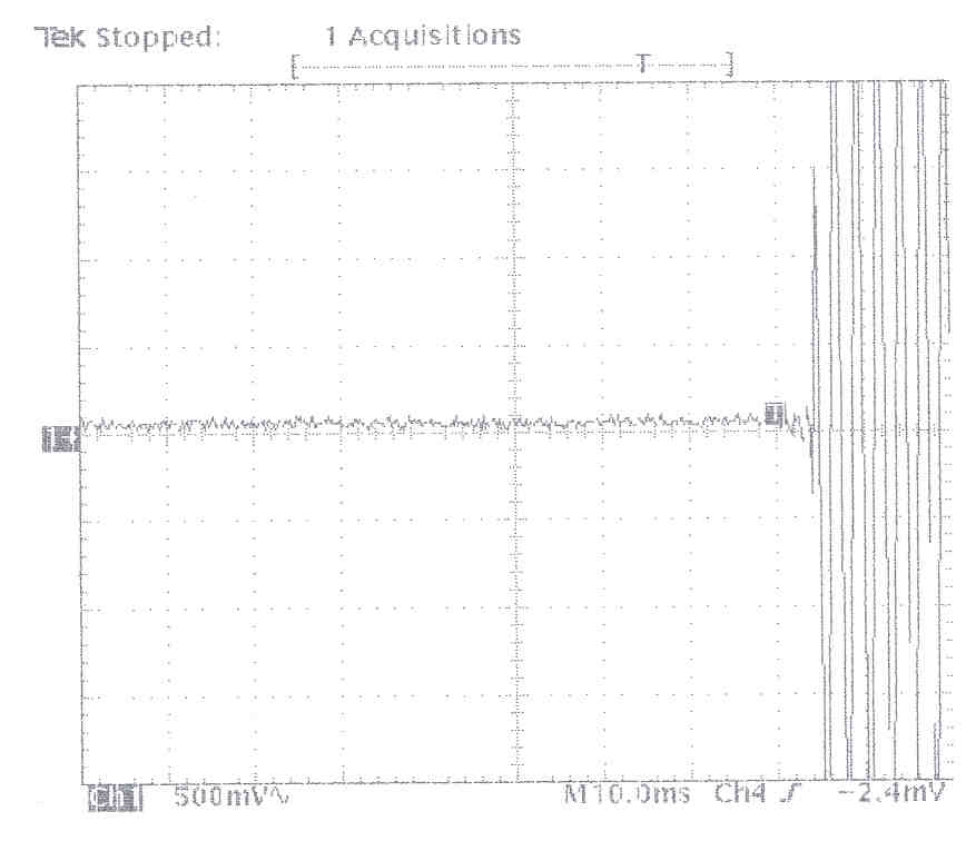
FCC ID: ARUSRU50ABC MEASUREMENT/TECHNICAL REPORTMEASUREMENT/TECHNICAL REPORT COMPANY NAME:COMPANY NAME:RELM CommunicationsRELM Communications MODEL:MODEL:S-Series (Models SRU50A,S-Series (Models SRU50A, SRU50B, and SRU50C)SRU50B, and SRU50C) FCC ID:FCC ID:ARUSRU50ABCARUSRU50ABC DATE:DATE:August 31, 1998August 31, 1998 This report concerns (check one): This report concerns (check one): Original grantOriginal grant X X Class II change_____ Class II change_____ Equipment type: Equipment type: Transceiver Transceiver Deferred grant requested per 47 CFRDeferred grant requested per 47 CFR 0.457(d)(1)(ii)? yes_____ No0.457(d)(1)(ii)? yes_____ No X X If yes, defer until:_________________If yes, defer until:_________________ date date N.A. N.A. agrees to notify the agrees to notify the Commission byCommission by N.A. N.A. date date of the intended date of announcement of theof the intended date of announcement of the product so that the grant can be issued onproduct so that the grant can be issued on that date.that date. FCC ID: ARUSRU50ABC Report prepared by:Report prepared by: United States United States Technologies, Inc.Technologies, Inc. 3505 Francis Circle 3505 Francis Circle Alpharetta, GA 30004 Alpharetta, GA 30004 Phone Number: (770) Phone Number: (770) 740-0717 740-0717 Fax Number: (770) Fax Number: (770) 740-1508 740-1508 TABLE OF CONTENTSTABLE OF CONTENTS GENERAL INFORMATIONGENERAL INFORMATION Users Manual Includes: Theory of Operation/ Technical Description Tune Up Procedure Parts Lists Schematics Labeling Information Photographs TESTS AND MEASUREMENTSTESTS AND MEASUREMENTS Product Description Test Methodology EUT and Peripherals Test Facility FCC ID: ARUSRU50ABC Test Equipment Modifications Measurement Procedure - RF Power Output - Bandwidth of Fundamental Emission - Spurious Emissions at Antenna Terminals - Field Strength of Spurious Radiation Emissions - Frequency Stability - Transient Frequency Behavior FCC ID: ARUSRU50ABC GENERAL INFORMATION FCC ID: ARUSRU50ABC USERS MANUAL Includes: Theory Of Operation Tune Up Procedure This has been provided in 2 separateThis has been provided in 2 separate files from Relm Communications (Wordfiles from Relm Communications (Word relmmanual.doc & relmmanual1.doc)relmmanual.doc & relmmanual1.doc) FCC ID: ARUSRU50ABC PARTS LIST At the time of submital, this informationAt the time of submital, this information was not available from Relmwas not available from Relm CommunicationsCommunications FCC ID: ARUSRU50ABC SCHEMATICS These have been provided in separateThese have been provided in separate filesfiles FCC ID: ARUSRU50ABC LABELING INFORMATION This information has been provided in aThis information has been provided in a separate file from Relm Communicationsseparate file from Relm Communications (Word Document fcclbl.doc)(Word Document fcclbl.doc) FCC ID: ARUSRU50ABC PHOTOGRAPHS FCC ID: ARUSRU50ABC PHOTOGRAPHSPHOTOGRAPHS Photo 1. EUT, Front View Photo 2. EUT, Rear View Photo 3. EUT, Internal View, Cover Removed Photo 4. EUT, Digital Board, Top View Photo 5. EUT, Digital Board, Bottom View Photo 6. EUT, RX Portion, Inside Top Cover Photo 7. RX Portion, Main Board, Top Cover Removed Photo 8. RX Portion, Main Board, Top Cover & Daughter Board Removed Photo 9. RX Portion, Main Board, Bottom View Photo 10. RX Portion, Top View Of Daughter Board Photo 11. RX Portion, Bottom View Of Daughter Board Photo 12. RX Portion, Inside Bottom Cover Photo 13. EUT, TX Portion, Inside Top Cover Photo 14. TX Portion, Main Board, Top Cover Removed Photo 15. TX Portion, Main Board, Top Cover & Daughter Board Removed Photo 16. TX Portion, Main Board, Bottom View Photo 17. TX Portion, Top View Of Daughter Board Photo 18. TX Portion, Bottom View Of Daughter Board Photo 19. TX Portion, Inside Bottom Cover Photo 20. Top Of Power Amplifier Board These have been provided in separate filesThese have been provided in separate files FCC ID: ARUSRU50ABC TESTS AND MEASUREMENTS FCC ID: ARUSRU50ABC TESTS AND MEASUREMENTSTESTS AND MEASUREMENTS Product DescriptionProduct Description The Equipment Under Test (EUT) is the RELM Communications, Inc. S Series (Models SRU50A, SRU50B, & SRU50C). The S Series (Models SRU50A, SRU50B, & SRU50C) of radio systems uses state-of-the-art design and construction methods to deliver a range of high- performance, ultra-reliable radio devices. These radio systems are ideally suited for use in VHF or UHF two- way voice radio systems; however, the S Series (Models SRU50A, SRU50B, & SRU50C) can perform any number of applications where the added advantage of linear frequency and phase response from DC to 5KHz can be used. The S Series (Models SRU50A, SRU50B, & SRU50C), unlike conventional PLL radio systems, uses a two- point modulation method synthesizer for extended low- end VF transmit frequency response. The flexibility of the S Series (Models SRU50A, SRU50B, & SRU50C) allows it to be configured for a wide range of applications: ·Standard or wideband voice, full duplex radio ·Cellular or trunking systems ·POCSAG paging transmitter ·Direct FSK modulation ·Two- or four-level FSK transmissions ·Other paging formats ·Cross band link or repeater Three separate units were tested to cover the 400-435 MHz (N2), 450-485 MHz (P2), and 485-520 MHz (Q) bands. These units are identical in design nature except for a few minor component value changes to cover each individual band. Each model equates to the following frequency bands: SRU50A400-435 MHz SRU50B450-485 MHz SRU50C485-520 MHz FCC ID: ARUSRU50ABC Test Methodology Test Methodology Prepared in accordance with the requirements of FCC Rules and Regulations Part 2 Subpart F, Paragraphs 2.983 through 2.999 and applicable portions of Parts 24, 74, 80 and 90. All measurements are peak unless stated otherwise. The video filter associated with the spectrum analyzer was off throughout the evaluation process. Interconnecting cables were manipulated as necessary to maximize emissions. A block diagram of the tested system …
Text truncated - open the document above for the full version.
Test Report
FCC Type AcceptanceMX800 TCXOTEMP o C (PPM) 60 -0.216 50 -0.029 40 -0.022 30 0.147 20 0.282 10 0.325 0 0.344 -10 0.362 -20 0.446 -30 0.522 Equipment Cal Due HP 8920A 8/2/98 Test performed by: Fluke 75 2/17/99 Ratelco pwr supply N/A Kenneth Klyberg Engineering Technician Frequency Stability Vs Temperature -1.500-1.000-0.500 0.0000.5001.0001.500 6 0 5 0 4 0 3 0 2 0 1 0 0 - 10 - 20 - 30 Temperature (Degrees Centigrade) Frequency Error (PPM)
Test Report
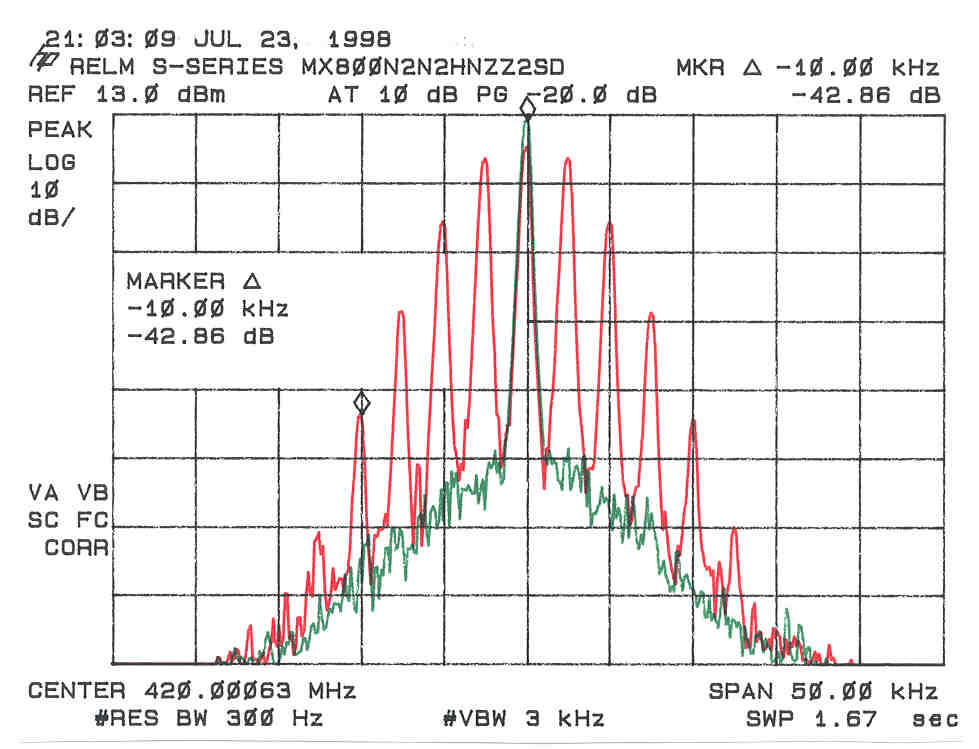
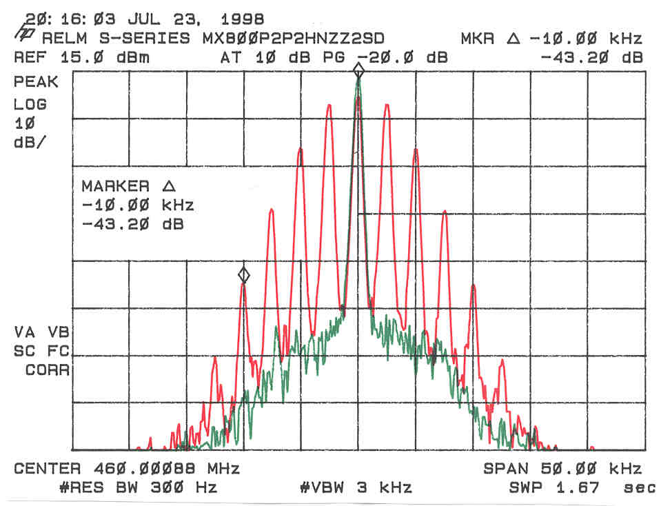
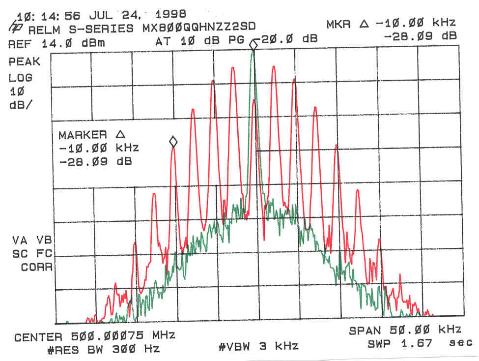
Emission Bandwidth for 2.5 kHz deviation, 3 kHz max modulation frequency or a 11K0F9E emission. Emission Bandwidth for 2.5 kHz deviation (2.15 kHz of voice and 350 Hz of data), 3 kHz max modulation frequency or a 11K0F9W emission.
Test Report
FCC ID: ARUSRU50ABC FIELD STRENGTH OF SPURIOUS RADIATION Test Date:January 18, 1999 UST Project:98-280 Customer:RELM Communications Model:S Series (Models SRU50A, SRU50B, & SRU50C) 12.5 kHz Channel Bandwidth FCC Minimum Standard: 50 + 10 log (58.6) = 67.6 dB Fundamental = Corrected Reading in Far Field (30m) = 17.2 dBm FREQ (MHz)MEASUREMENT @ 3 m (dBm)* CORRECTION AF + CL + AMP GAIN CORRECTED MEASUREMENT @ 30 m (dBm) ATTENUATED LEVEL BELOW CARRIER POWER (dB) 900.0-76.030.5-65.582.7 1350.0-33.4-6.1-59.576.7 1800.0-49.6-3.8-73.490.6 2250.0-29.7-1.2-50.968.1 2700.0-45.10.6-64.581.7 3150.0-43.61.4-62.279.4 3600.0-48.23.0-65.282.4 4050.0-57.84.7-74.892.0 4500.0-61.34.3-77.094.2 SAMPLE CALCULATION: Results dBm @ 30 m: -76.0 + 30.5 - 20 = -65.5 CONVERSION FROM 3 METERS TO 30 METERS = 20 dB * =Measurments were made with a 50Ω termination connected to the antenna port. Results Reviewed By: Name: Tim R. Johnson
Contact Information
Applicant
Walter C. Simciak(Engineering Manager)
Technical Contact
U.S. Technologies, IncTimothy R Johnson
[email protected]770-740-0717
3505 Francis Circle · Alpharetta, Georgia · United States
Non-Technical Contact
U.S. TechnologiesTimothy R Johnson
[email protected]770-740-0717
Test Firm
US TechSandy McEnery
Technical Specifications
| # | Rule Parts | Frequency Range | Power Output | Emission | Tolerance |
|---|---|---|---|---|---|
| 12 | 90.21 | 485 MHz - 520 MHz | 50 W | 11K0F9W | 1 ppm |
Other Applications from RELM Communications Inc
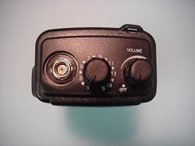
ARURPU416B
Dec 15, 2004UHF Transceiver
Equipment Class
TNF - Licensed Non-Broadcast Transmitter Held to Face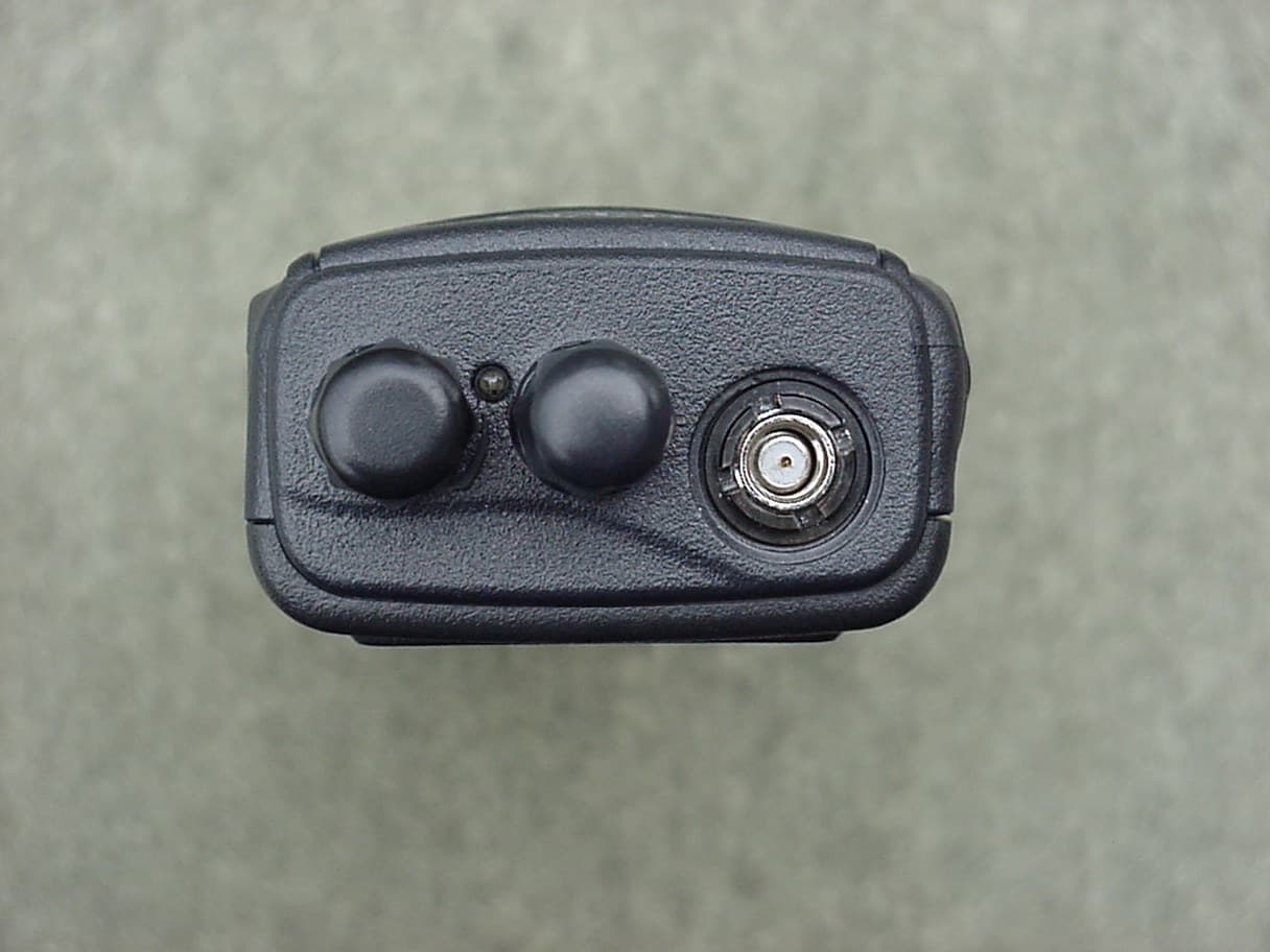
ARURPU499A
Apr 25, 2004UHF Land Mobile Radio
Equipment Class
TNF - Licensed Non-Broadcast Transmitter Held to Face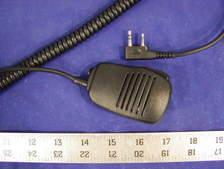
ARURPV599A
Dec 22, 2002VHF FM Transceiver
Equipment Class
TNF - Licensed Non-Broadcast Transmitter Held to Face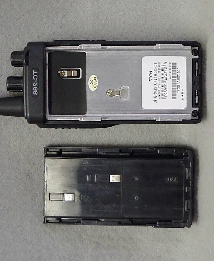
ARURPV516A
Jan 03, 2002VHF FM Transceiver
Equipment Class
TNF - Licensed Non-Broadcast Transmitter Held to Face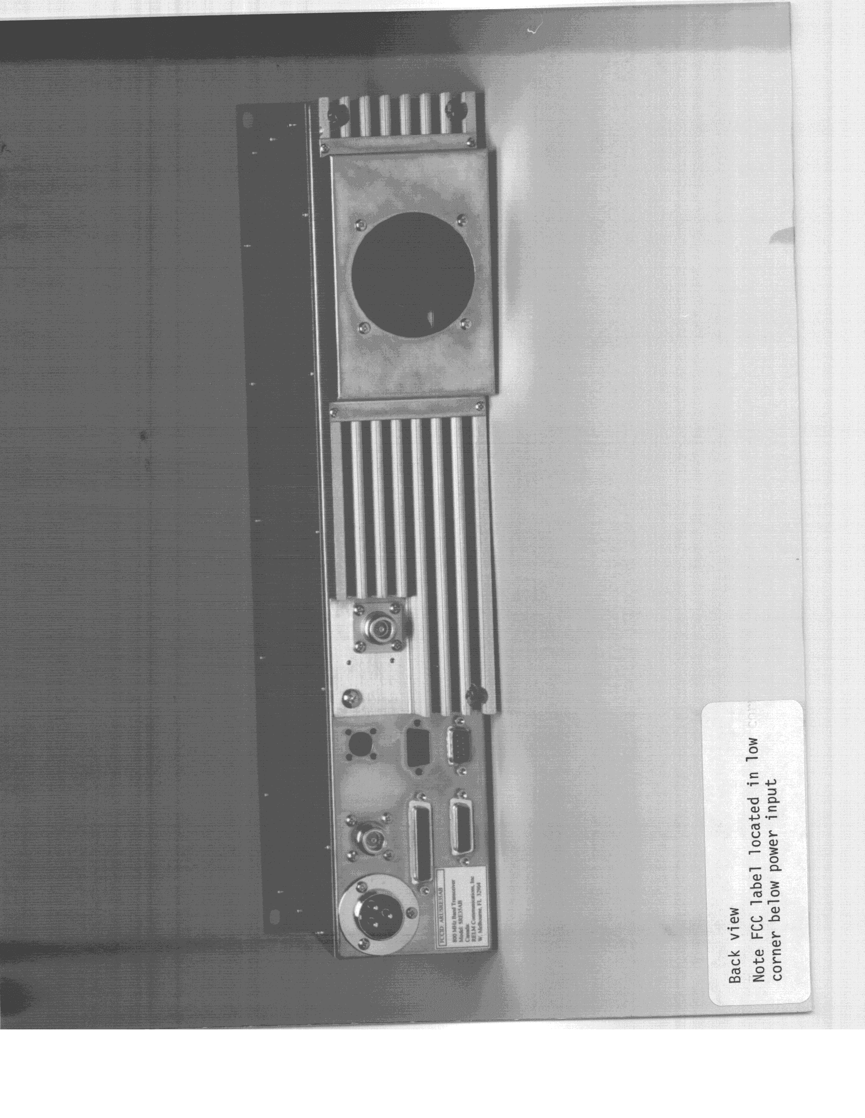
ARUSRE35AB
Oct 06, 1998TNB - Licensed Non-Broadcast Station Transmitter
Equipment Class
TNB - Licensed Non-Broadcast Station Transmitter