ARURPV599AVHF FM Transceiver
RELM Communications Inc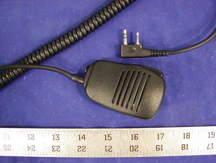
Click to zoom
Application Details
- Equipment Class
- TNF - Licensed Non-Broadcast Transmitter Held to Face
- Date of Grant
- Dec 22, 2002
- Application Purpose
- Original Equipment
- Date of Application
- Sep 23, 2002
- Equipment Note
- VHF FM Transceiver
- Frequency Range
- 148.00000000 - 174.00000000
- Company
- RELM Communications Inc
- Country
- United States
Documents & Files
Document Text
Text extracted from the exhibit documents filed with the FCC. Open a document above to read the original.
Users Manual
PRELIMINARY PRV599A VHF PORTABLE TWO-WAY RADIO OWNER’S MANUAL PRELIMINARY Shenzhen HYT Science & Technology Co., Ltd. THANK YOU Thank you for your purchase of HYT two-way portable radio. This easy-to-use radio adopts the latest advanced technology, providing reliable communications in high efficiency. Before operate this radio, please read this manual carefully to be acquainted with its features. PRELIMINARY CONTENTS USER SAFETY INFORMATION...........................................................................................4 SUPPLIED ACCESSORIES ...................................................................................................7 ANTENNA, BATTERY AND OTHER ACCESSORIES.................7 1, BATTERY ...................................................................................................................7 2, ANTENNA ..................................................................................................................8 3, EXTERNAL SPK-MIC JACK ....................................................................................8 4, BELT CLIP ..................................................................................................................8 GETTING ACQUAINTED..................................................................................9 ■CONTROL KNOBS, FUNCTION KEYS AND JACKS..............................................9 ■LCD.............................................................................................................................10 FEATURES AND OPERATION.....................................................................11 1,POWER ......................................................................................................................11 2,VOLUME ...................................................................................................................11 3,MONITOR..................................................................................................................11 4, SELECT CHANNEL.................................................................................................11 5,SELECT SQUEL LEVEL ..........................................................................................11 6 RECEIVE ...................................................................................................................12 7, TRANSMIT ...............................................................................................................12 8,CHANNEL SCAN......................................................................................................13 9, FREQUENCY REVERSE/TALK AROUND.........................................................13 10, DTMF SELECTIVE CALL ....................................................................................14 11, CODE SQUELCH ...................................................................................................15 12, SELECTIVE CALL.................................................................................................15 13, TWO-TONE SELECTIVE CALL...........................................................................16 14, SELECTABLE CTCSS ...........................................................................................16 15, AUTO-RESPONDER ..............................................................................................16 16, CALL ALERT TONE ..............................................................................................17 CARE AND CLEANING....................................................................................17 PRELIMINARY USER SAFETY INFORMATION READ THIS IMPORTANT INFORMATION ON SAFE AND EFFICIENT OPERATION BEFORE USING YOUR HYT PORTABLE TWO-WAY RADIO. ◇ Only qualified technicians are allowed to repair this product. ◇ Turn off your radio prior to entering any area with a potentially explosive atmosphere. Do not remove, install, or charge batteries in such areas. ◇ Do not use any portable radio that has a damaged antenna. If a damaged antenna comes into contact with your skin, a minor burn can result. ◇ Do not expose the radio in direct sunlight for a long time or place it close to a heating source. User Safety, Training, and General Information READ THIS IMPORTANT INFORMATION ON SAFE AND EFFICIENT OPERATION BEFORE USING YOUR RELM HANDHELD PORTABLE TWO-WAY RADIO. Compliance with RF Energy Exposure Standards Yo u r RELM two-way radio is designed and tested to comply with a number of national and international standards and guidelines (listed below) regarding human exposure to radio frequency electromagnetic energy. This radio complies with the IEEE (FCC) and ICNIRP exposure limits for occupational/controlled RF exposure environment at duty cycles of up to 50% talk-50% listen and should be used for occupational use only. In terms of measuring RF energy for compliance with the FCC exposure guidelines, your radio radiates measurable RF energy only while it is transmitting (during talking), not when it is receiving (listening) or in standby mode. Note: The approved batteries supplied with this radio are rated for a 5-5-90 duty cycle (5% talk-5% listen-90% standby), even though this radio complies with the FCC occupational RF exposure limits at duty cycles of up to 50% talk. Your RELM two-way radio complies with the following of RF energy exposure standards and guidelines: • United States Federal Communications Commission, Code of Federal Regulations; 47CFR part 2 sub-part J • American National Standards Institute (ANS)/Institute of Electrical and Electronic Engineers (IEEE) C95. 1-1992 PRELIMINARY • Institute of Electrical and Electronic Engineers (IEEE) C95. 1-1999 Edition • International Commission on Non-Ionizing Radiation Protection (ICNIRP) 1998 • Ministry of Health (Canada) Safety Code 6. Limits of Human Exposure to Radio frequency Electromagnetic Fields in the Frequency Range from 3kHz to 300GHz, 1999 • Australian Communications Authority Radio communic…
Text truncated - open the document above for the full version.
Users Manual
User Manual For RPV599A Programming Software Version 1.00 ≤ Introduction RPV599A Programming Software described in this user manual is applicable to RPV599A Transceiver. This software is mainly used for writing data to your transceiver or reading data from your transceiver via your computer and copyrighted by Relm Corporation. ≤ Statement “It is forbidden to transmit this device on marine frequencies 156.10 MHz (Marine Channel 02), 156.20 MHZ (Marine Channels 04 and 04A), 156.025 MHz (Marine Channel 60), and 156.125 MHz (Marine Channel 62).” Programming software, accessories, and procedures are issued only to authorized distributors and repair facilities. The radio cannot be programmed for any frequency change, including channel spacing (12.5/15 kHz vs. 25/30 kHz), by a user in the field. ≤ Install Software In your disk, which is presented to you together with your transceiver, you can see one setup file of our software, which is named by RPV599ASetup.EXE. By clicking the setup file, installing will run automatically. During the installing process, you can do something according to the setup wizard. When finished, the software has been installed in your computer. ≤ Connect a Cable After installing the software, but how to use it with your transceiver You will have a cable that connects your computer with your transceiver. You can connect your computer to your transceiver according to the following steps. Insert one end of the cable to the serial port (COM1 or COM2) of your computer, the other end to the Speaker/Microphone “ port of the transceiver. Before operating the transceiver, you are required to open the power switch of the transceiver. ≤ Run Software There is a shortcut to it on your computer Desktop and Program Manager group. Execute this shortcut “RPV599A Programming Software“ to run the program. The Main Interface displays as follow. Figure 1 ≤ Select Communication Port When changing the connecting serial port, you must select the corresponding communication settings. To select a different communication port, click Communication of Option Menu and set a new port. Figure 2 When popuping the dialog, you can choose either COM1 or COM2 as your communication port. Figure 3 ≤ Set the data Channel Unit Settings When you run the program, you can see three different interfaces by clicking the Option menu item. The first submenu of Channel Settings is for setting the channels data; the second submenu of Radio Configuration is for setting the whole radio function data and scan data; the last submenu of Set DTMF/TTS is just for setting radio signals: DTMF or TTS(Two-Tone Signaling). In the main interface, you can see a form of the first 20 channels. There are fives group and each group has 20 channels except for the fifth group. In each main interface you can set the channel data. There are 13 columns for each channel. You can set each column with your wanted value. In the top of the main interface, you can see two buttons which are named Prev and Next. By clicking either button, the main interface will be changed to the next group of 20 channels. Radio Configuration Now if you click the submenu item of Radio Configuration under Option menu item, you will see a new interface. In this interface you can set all the whole radio settings as bellows. Figure 4 ü Model There are two items. This program is just for one model of transceiver RPV599A. The frequency band is 148MHz~174MHz. ü Scan Information You can set all the data relevant to scan. The value of each item is listed in the Combo Box. Whole Radio Settings In this frame, you can set all the function data. The value of each item is also listed in the Combo Box. Here you will be reminded to notice the last two items Rx TTS(A) and Rx TTS(B). These two items is to set the TTS tone frequency for the radio. ü Key Program In this frame, you can set different functions for the six keys on the panel of the radio. Each key can be set to be any of the six functions. Note: You’d better not set more one key to be the same function. Set DTMF/TTS If you want to set DTMF/TTS, you can click another submenu item Set DTMF/TTS. In this interface, you see two frames. One is DTMF and the other is TTS. You can set any data for them. Figure 5 ü DTMF In this frame, you can set all the DTMF data settings. The value each DTMF item is listed in combo box except for Connect ID and Disconnect ID. These two items need you to enter the code number when you want. ü TTS In this frame, you can set all the tone frequency and tone time for TTS. In the two above interfaces, you will see there are two buttons on the bottom of the interface, which are OK and Cancel. When you finish to set all your wanted data, you can click the OK button to save them. If you have just take a mistake to modify them, you can click the Cancel button to restore the old data. See the Help File for details about Set the Data. ≤ Read the Data Select the Operate Menu and click the Read item, you will read frequencies and other data of the transceiver connecting to your computer when you open its power switch. Of course, you can also click Read Icon of Toolbar. While reading, the program display the following figure. Figure 6 Display as follow if data are read correctly. Figure 7 ≤ Write the Data If you need to write frequencies and other data to the transceiver, select the Operate Menu and click Write item, or click Write Icon of Toolbar. While writing, the program popup the following figure. Figure 8 If data are written correctly, display: Figure 9 ≤ Other Operation Open a File When you set all the data, you can save them to be a file which extend file name is .rpv. When you need these data, you open the file which has been saved by clicking the submenu Open under the menu File(F). The figure is as follows. Figure 10 Save Clicking this submenu or icon, you can directly save the data in your opened file. If you don’t open any file, clicking it will popup a Save dialog to recommend you to save them in …
Text truncated - open the document above for the full version.
Cover Letter(s)
December 6, 2002 Gentlemen: Regarding the RPV599 Portable Transceiver currently being considered for certification, the following items apply. RPV599 Series radios can be programmed in four different ways: A. With a computer, RELM’s proprietary RPV599A editor software, and a PCRP interface cable. B. With the RPV599A’s external controls. C. With a CCRP cloning cable, clone programmed settings from one RPV599A portable radio to another RPV599A. D. Wireless clone mode, clone programmed settings from one RPV599A portable radio to another RPV599A. Programming software, accessories, and procedures are issued only to authorized distributors and repair facilities. The radio cannot be programmed for any frequency change, including channel spacing (12.5/15 kHz vs. 25/30 kHz), by a user in the field. Sincerely, Engineering Support Supervisor Federal Communications Commission P.O. Box 429 Columbia, MD 21045 RELM Wireless Corp. 7100 Technology Drive West Melbourne, FL 32904
Cover Letter(s)
December 18, 2002 Gentlemen: Regarding the RPV599A Portable Transceiver currently being considered for certification, the following two items apply for the RPV599A to comply with part 80.203. 1. The following statement will be included in the programming manual: “It is forbidden to transmit this device on marine frequencies 156.10 MHz (Marine Channel 02), 156.20 MHZ (Marine Channels 04 and 04A), 156.025 MHz (Marine Channel 60), and 156.125 MHz (Marine Channel 62).” 2. Programming software, accessories, and procedures are issued only to authorized distributors and repair facilities. The radio cannot be programmed for any frequency change, including channel spacing (12.5/15 kHz vs. 25/30 kHz), by a user in the field. Sincerely, Engineering Support Supervisor Federal Communications Commission P.O. Box 429 Columbia, MD 21045 RELM Wireless Corp. 7100 Technology Drive West Melbourne, FL 32904
External Photos
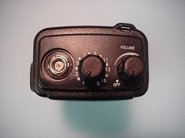
EXHIBIT C - EUT EXTERNAL PHOTOGRAPHS Chassis - Front View Chassis - Back View Chassis - Top View Chassis - Side View Power Adapter Charger Top View Charger Bottom View Radio Interface Box Speaker
Internal Photos
EXHIBIT C - EUT INTERNAL PHOTOGRAPHS Main Board - Component View Main Board - Solder View Antenna Attachment
Operational Description
SPECIFICATIONS Frequency Range 148 174MHz Number of Channels 32 Channel Spacing 25kHz (12.5kHz) Operation Voltage 7.5V Battery Life More than 8 hours Operation Temperature -30 60 Sensitivity 0.18 μV Modulation Acceptance ±7kHz Channel Selectivity More than 65dB Intermodulation More than 65dB Spurious Response More than 60dB Audio Power Output 00mW @ distortion less than Frequency Stability ±5×10 -6 RF Power Output High/Low 5W/1W Spurious and Harmonics Less than -70dB Modulation 16KØF3E (11K0F3E) Max. Frequency Deviation ±5 kHz FM Noise -45dB Modulation Distortion Less than5%
Parts List/Tune Up Info
RPV599A 55 Parts List Ref. No. Part No. Description Ref. No.Part No. Description 1 15061020 PTT bezel R23 01034732 47K 2 16062010 PTT keypad R24 01034732 47K 3 15061120 housing, front R25 01034732 47K 4 14063080 spring, battery latch R26 01031042 100K 5 14063090 springy metal, battery latch R27 01031042 100K 6 15061090 latch R28 01031022 1.0K 7 16062070 gasket, speaker R29 01034722 4.7K 8 13010R50 speaker R30 01033912 390Ω 9 15061040 cover ,SP/MIC jacks R31 01031022 1.0K 10 14063130 retainer (SP/MIC) R32 01031022 1.0K 11 17064020 insulator, speaker R34 01031002 10Ω 12 16062020 keypad R35 01031002 10Ω 13 17067020 LCD bezel R36 01031832 18K 14 14066200 screw, antenna base R37 01031022 1.0K 15 14063200 spring (knob) R38 01031022 1.0K 16 15061030 knob, channel selector R39 01031022 1.0K 17 15061100 knob, on/off/volume R40 01031022 1.0K 18 14066300 screw (potentiometer) R41 01031022 1.0K 19 15061110 top panel R42 01033342 330K 20 17067040 reflector ,paper R43 01031022 1.0K 21 15061010 LCD filter R44 01031022 1.0K 22 16062040 connector R45 01031022 1.0K 23 14063180 spring connector R46 01031022 1.0K 24 19060070 LCD R47 01031022 1.0K 25 17067020 insulator, LCD R48 01034722 4.7K 26 14063010 LCD fixture R49 01030002 0Ω 27 16062050 water resistant gasket, jacks R50 01031022 1.0K 28 15061140 holder, anode piece R51 01031042 100K 29 14063100 anode contact piece R52 01031242 120K 30 17067070 insulator, anode R53 01034732 47K 31 17064010 anode sponge pad R54 01031022 1.0K 32 16062060 gasket, top panel R55 01032722 2.7K 33 14063240 antenna connector R56 01031002 10Ω 34 15061050 lightpipe (TX/RX) R57 01031042 100K 35 14063110 PA module holder R58 01032232 22K 36 14063120 PA module contact R59 01033322 3.3K 37 14063140 fixture (chassis) R60 01032242 220K 38 14063070 cathode contact, battery R61 01031032 10K 39 14063060 aluminium chassis R62 01033322 3.3K 40 17067310 label, round R63 01031032 10K 41 17067262 label, model R64 01031032 10K 42 17067060 insulator R65 01031022 1.0K 43 14063150 belt clip R66 01031022 1.0K R67 01031032 10K R68 01032722 2.7K RPV599A 56 R69 01038212 820Ω R1 01034722 4.7K R70 01034732 47K R2 01034722 4.7K R72 01031042 100K R3 01030002 0 R73 01031032 10K R5 01031042 100K R74 01034742 470K R6 01031042 100K R75 01033332 33K R7 01031022 1.0K R76 01034712 470Ω R8 01031022 1.0K R78 01031542 150K R9 01031022 1.0K R79 01031522 1.5K R10 01031042 100K R80 01036812 680Ω R11 01031032 10K R81 01031242 120K R12 01034722 4.7K R83 01033331 33K R13 01034722 4.7K R84 01033331 33K R14 01034722 4.7K R85 01032431 24K R15 01034722 4.7K R86 01033931 39K R16 01031022 1.0K R87 01031032 10K R17 01031022 1.0K R88 01031031 10K R18 01034722 4.7K R90 01031022 1.0K R19 01034722 4.7K R91 01031012 100Ω R20 01032222 2.2K R92 01034732 47K R21 01031032 10K R93 01034732 47K R22 01031512 150 R94 01031032 10K R97 01031022 1.0K R172 01035622 5.6K R98 01036822 6.8K R173 01030002 0 R99 01031032 10K R174 01034732 47K R100 01033322 3.3K R175 01031542 150K R101 01031032 10K R176 01031542 150K R104 01031042 100K R177 01034722 4.7K R105 01031032 10K R178 01031012 100 R106 01032222 2.2K R179 01033302 33 R107 01035622 5.6K R180 01033922 3.9K R108 01033932 39K R181 01031522 1.5K R109 01031042 100K R182 01031222 1.2K R110 01031042 100K R185 01035622 5.6K R111 01033322 3.3K R186 01033342 330K R112 01031032 10K R188 01034702 47 R113 01036842 680K R190 01031022 1.0K R114 01033332 33K R191 01031032 10K R115 01034732 47K R192 01031022 1.0K R116 01031842 180K R193 01035612 560 R117 01031522 1.5K R194 01030002 0 R118 01031242 120K R195 01034722 4.7K R119 01034732 47K R196 01031522 1.5K R120 01036842 680K R197 01033312 330 R121 01031042 100K R198 01032222 2.2K R124 01031832 18K R199 01031032 10K R125 01034732 47K R200 01031032 10K R127 01030002 0 R201 01033302 33 R128 01031042 100K R202 01031012 100 R129 01032712 270 R203 01030002 0 R130 01033322 3.3K R204 01031532 15K RPV599A 57 R131 01038232 82K R207 01031022 1.0K R132 01031032 10K R208 01034732 47K R209 01032222 2.2K R135 01032712 270 R210 01031541 150K R136 01031852 1.8M R211 01031541 150K R137 01031832 18K R212 01030002 0 R138 01033332 33K R213 01031532 15K R139 01031032 10K R215 0106R502 0.5 R140 01031832 18K R216 01031042 100K R141 01031042 100K R217 0106R502 0.5 R142 01033932 39K R218 0106R502 0.5 R143 01031242 120K R219 01031532 15K R145 01031042 100K R220 01031541 150K R146 01031042 100K R221 01031541 150K R147 01031032 10K R222 01036842 680K R148 01036812 680 R223 01031532 15K R149 01035642 560K R224 01031541 150K R150 01031522 1.5K R225 01034702 47 R151 01031042 100K R226 01031512 150 R152 01031032 10K R227 01032712 270 R153 01031852 1.8M R228 01031541 150K R155 01034722 4.7K R229 01034722 4.7K R156 01033922 3.9K R230 01032712 270 R157 01036812 680 R231 01035632 56K R158 01033332 33K R232 01032232 22K R159 01031542 150K R233 01033332 33K R160 01031542 150K R234 01031512 150 R161 01031022 1.0K R235 01031002 10 R162 01033322 3.3K R236 01033312 330 R163 01031042 100K R237 01031032 10K R164 01033922 3.9K R238 01034742 470K R165 01031232 12K R239 01031822 1.8K R166 01033932 39K R240 01032732 27K R167 01031842 180K R241 01034712 470 R168 01031042 100K R242 01031052 1.0M R243 01030002 0 R169 01031812 180 R171 01033922 3.9K R245 01031042 100K R246 01031022 1.0K C51 02031023 1000pF R247 01031012 100 C52 02051053 1.0uF R248 01031012 100 C53 02031023 1000pF C55 0206105Z 1.0uF C56 02052243 0.22uF CP1 014D102A 1K*4 C57 02033923 3900pF CP2 014D102A 1K*4 C58 02031023 1000pF CP3 014D103A 10K*4 C59 T0606106 10uF CP4 014D472A 4.7K*4 C62 02033332 0.033uF C63 02031812 180pF C64 T0606475 4.7uF TH1 0139222B 2.2K C65 T0510684 0.68uF TH2 0139222B 2.2K C66 T0510684 0.68uF RPV599A 58 TH3 0139222B 2.2K C67 02034713 470pF TH4 0139222B 2.2K C68 02036813 680pF TH5 0139222B 2.2K C69 02031023 1000pF C70 02031023 1000pF C71 02034702 47pF C1 02032733 0.027uF C72 02031233 0.012uF C2 02032733 0.027uF C73 02031233 0.012uF C3 02031023 1000pF C74 02034723 4700pF C4 02031033 0.010uF C75 02034733 0.10uF C5 02031033 0.…
Text truncated - open the document above for the full version.
Parts List/Tune Up Info
RPV599A 46 Adjustment Required Test Equipment Stabilized Power supply 1. The supply voltage can be changed between 5V and 8V, and the current is 3A or more. 2. The standard voltage is 7.5V. DC Ammeter 1. Class 1 ammeter (17 ranges and other features). 2. The full scale can be set to either 300mA or 3A. 3. A cable of less internal loss must be used. Digital Voltmeter 1. Voltage range: FS=18V or so 2. Input resistance: 1MΩ or more Oscilloscope 1. Measuring range: DC to 30MHz 2. Provides highly accurate measurements for 5 to 25MHz. Dummy Load 8Ω 3W or more RADIO COMMUNICATION TESTER 2955B Spectrum Analyzer SG815 Note: 1. Use a non-conductive rod such as a Bakelite rod for adjustment (especially of trimmers and coils) 2. You can substitute a RADIO COMMUNICATION TEST SET (2955B) for Frequency Counter, Power Meter, RF VTVM, Linear Detector, AF Voltmeter and Standard Signal Generator. 3. You can use a Spectrum Analyzer substituting Tracking Generator. TC1: Frequency adjustment TC2: Transmit lock voltage adjustment TC3: Receive lock voltage adjustment VR1: CDCSS waveform adjustment VR2: DEV adjustment L24: L26: Band-pass filter waveform adjustment L32: ANT: Antenna connector SP: Speaker jack MIC: Microphone jack CH: Channel selector VR3: DTMF DEV adjustment Key: DTMF key terminal CV: Lock voltage test terminal Alignment Mode (Alignment procedure used during radio repairing) Operation 1. Turn POWER ON while pressing [LAMP] and [TA], in about 2 seconds, the radio enters the Test Mode. 2. Press [TA] in Test Mode, frequency is displayed on LCD. After selecting the frequency, press [LAMP] and [LO] simultaneously, radio enters Adjustment Mode, and ” tUnE” is displayed on LCD. 9 RPV599A 47 Adjusting Transmit Power Use this procedure to adjust the transmit High Power or Low Power level. 1. Connect the power meter to the radio. 2. Set the frequency and then set the “tUnE” display. 3. Transmission is performed automatically at High Power when the [PTT] key is pressed. The display “H XXX” now appears. (XXX=0 to 255) 4. Adjust the [CHANNEL SELECTOR] while observing the power meter in order to obtain the transmit power needed. Turn the control clockwise for an increase in power, and turn counterclockwise for a decrease in power. 5. Pressing any key other than [PTT] stores the alignment value into the memory and returns to the “tUnE” display. Pressing the [PTT] key stores the alignment value into the memory and switches to Low Power for transmit. The display “L XXX” appears at this time. 6. Adjust the [CHANNEL selector] while observing the power meter in order to obtain the transmit power needed. Turn the control clockwise for an increase in power and turn counterclockwise for a decrease in power. 7. Pressing any key stores the alignment value into the memory and returns to the “tUnE” display. Aligning the Battery Reference Value Use this procedure to adjust the reference value for issuing battery low voltage alarms. 1. Using an external power supply feed in the reference value at which you wish to trigger the alarm. 2. Set the frequency and then set the “tUnE” display. 3. Transmission is performed automatically at High Power when the [TA] key is pressed. The display “B XXX” now appears. (XXX=1 to 255). 4. Adjust by turning the [CHANNEL SELECTOR] counterclockwise when the red LED is lit, and by turning clockwise when the red LED is flashing. The point where the red LED is flashing indicates detection of the low voltage. 5. Pressing any key stores the reference value into the memory and returns to the “tUnE” display. Storing the BUSY Reference Value Use this procedure to align squelch values for 3 and 9. Other squelch levels are set based on these values. 1. Connect the signal generator to the radio. 2. Set the frequency and then set the “tUnE” display. 3. Input a signal at the level at which you want squelch 9 to open. 4. Press [MONI] to let the radio receive this signal. The display “9 XXX” now appears. (XXX =1 to 255) 5. Turn [CHANNEL SELECTOR] knob to the position where you want the squelch to open. 6. Pressing any key other than [MONI] stores this value into the memory and returns to the “tUnE” display. Press [MONI] to store the alignment value and to switch to the alignment of squelch 3, and now “3 XXX” displays. (XXX=1 to 255) 7. Next output a signal from the signal generator at which you want squelch 3 to open. Align by using the [CHANNEL SELECTOR] just as with squelch 9. 8. Pressing any key stores these values into the memory and returns to the “tUnE” display. Adjusting CTCSS Deviation Use this procedure to adjust the transmit CTCSS deviation. 1. Connect the modulation analyzer to the radio. 2. Select the frequency and CTCSS, and then set the “tUnE” display. 3. Press [SCN] to automatically start transmission and send the preset CTCSS. If the CTCSS was set to OFF, then 67.0Hz is sent. 4. While observing the modulation analyzer, adjust the deviation with the [CHANNEL SELECTOR]. 5. Pressing any key stores these values into the memory and returns to the “tUnE” display. Use the jig for adjustment to stabilize electrical operations. The frequency (TC1) and deviation (VR2) can be adjusted without using the jig. Use the jig as the following: 1. Insert the coaxial antenna connector into the jig. 2. Place the unit on the jig and fix it with four screws. 3. Solder the antenna terminal to the terminal of the unit. RPV599A 48 Notes: 1. Do not install the Ni-Cd battery when using the jig for adjustment, repair, or checking. If the Ni-Cd battery is installed, the relay terminal (+) may be damaged). 2. Using an external power supply as the radio power. VCO adjustment Receiver adjustment Fig.9 Measurement Adjustment Item Condition Test equipment Terminal Parts Method Specifications/R emarks 1.Setting Power supply voltage Battery terminal: 7.5V 1) TX HI Digital voltmeter CV TC3 3.8 ±0.05V 2)TX LOW Digital voltmeter CV TC3 ≥0.7V 3)RX HI Digital voltmeter CV TC2 3.8 ±0.05V 2.VCO lock voltage 4)RX LOW Digital voltmeter CV…
Text truncated - open the document above for the full version.
RF Exposure Info
Note: This test report is specially limited to the above client company and the product model only. It may not be duplicated without prior written consent of Bay Area Compliance Laboratory Corporation. This report must not be used by the client to claim product endorsement by NVLAP or any agency of the U.S. Government. SAR EVALUATION REPORT For RELM Communications Corp. 7100 Technology Drive West Melbourne, FL 32904 FCC ID: ARURPV599A September 9, 2002 This Report Concerns: Original Report Equipment Type: VHF Portable 2-way Radio Test Engineer: Jeff Lee Report No.: R0208193S Test Date: August 30, 2002 Reviewed By: Benjamin Jing Prepared By: Bay Area Compliance Laboratory Corporation 230 Commercial Street Sunnyvale, CA 94085 Tel: (408) 732-9162 Fax: (408) 732 9164 RELM Communications Corp. FCC ID: ARURPV599A Report #R0208193S SAR Evaluation Report Page 2 of 38 TABLE OF CONTENTS SUMMARY....................................................................................................................................................................3 1 - REFERENCE ...........................................................................................................................................................4 2 - TESTING EQUIPMENT.........................................................................................................................................5 2.1 EQUIPMENTS LIST & CALIBRATION INFO...............................................................................................................5 2.2 EQUIPMENT CALIBRATION CERTIFICATE...............................................................................................................5 3 - EUT DESCRIPTION .............................................................................................................................................10 4 - DOSIMETRIC ASSESSMENT SETUP...............................................................................................................11 4.1 MEASUREMENT SYSTEM DIAGRAM.....................................................................................................................12 4.2. SYSTEM COMPONENTS........................................................................................................................................13 4.3 MEASUREMENT UNCERTAINTY............................................................................................................................17 5 - SYSTEM EVALUATION .....................................................................................................................................18 5.1 SIMULATED TISSUE LIQUID PARAMETER CONFIRMATION...................................................................................18 5.2 SYSTEM ACCURACY VERIFICATION.....................................................................................................................18 5.3 SAR EVALUATION PROCEDURE...........................................................................................................................19 5.4 EXPOSURE LIMITS................................................................................................................................................20…
Text truncated - open the document above for the full version.
Contact Information
Applicant
Walter C. Simciak(Engineering Manager)
Technical Contact
Bay Area Compliance LaboratoryJohn Chan
[email protected](408) 732 9162
230 Commercial Street · Sunnyvale, California · United States
Non-Technical Contact
Bay Area Compliance Laboratory Corp.Rita Cai
[email protected](408) 732 9162
Test Firm
Bay Area Compliance LaboratoryJohn Chan
Technical Specifications
| # | Rule Parts | Frequency Range | Power Output | Emission | Tolerance |
|---|---|---|---|---|---|
| 2 | 22,74,80,9 | 148 MHz - 174 MHz | 4.37 W | 16K0F3E | 5 ppm |
Other Applications from RELM Communications Inc
ARURPU416B
Dec 15, 2004UHF Transceiver
Equipment Class
TNF - Licensed Non-Broadcast Transmitter Held to Face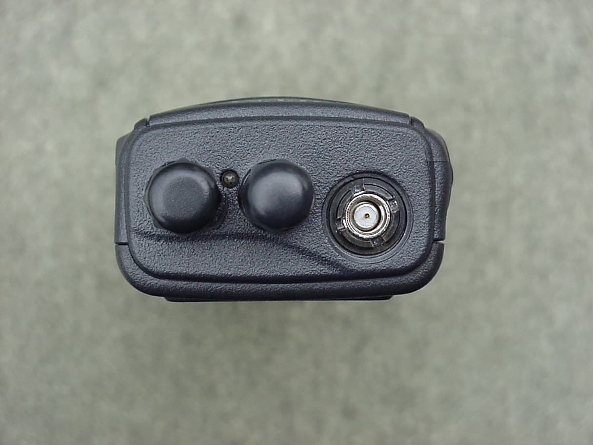
ARURPU499A
Apr 25, 2004UHF Land Mobile Radio
Equipment Class
TNF - Licensed Non-Broadcast Transmitter Held to Face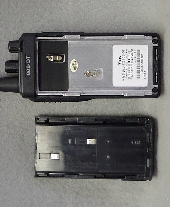
ARURPV516A
Jan 03, 2002VHF FM Transceiver
Equipment Class
TNF - Licensed Non-Broadcast Transmitter Held to Face
ARUSRU50ABC
Jan 25, 1999Repeater
Equipment Class
TNB - Licensed Non-Broadcast Station Transmitter
ARUSRE35AB
Oct 06, 1998TNB - Licensed Non-Broadcast Station Transmitter
Equipment Class
TNB - Licensed Non-Broadcast Station Transmitter