ATMUTX1Digital Wireless Audio Transmitter
Onkyo Home Entertainment Corporation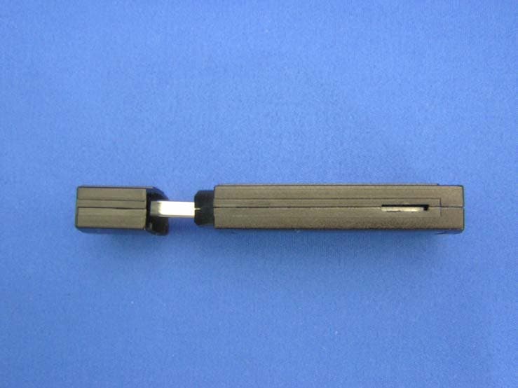
Click to zoom
Application Details
- Equipment Class
- DTS - Digital Transmission System
- Date of Grant
- Oct 08, 2006
- Application Purpose
- Original Equipment
- Date of Application
- Oct 08, 2006
- Equipment Note
- Digital Wireless Audio Transmitter
- Frequency Range
- 2412.00000000 - 2462.00000000
- Country
- Japan
Documents & Files
Document Text
Text extracted from the exhibit documents filed with the FCC. Open a document above to read the original.
Users Manual
En Wireless USB Audio Transport UWL-1 Instruction Manual Thank you for purchasing the Onkyo Wireless USB Audio Transport. Please read this manual thoroughly before making any connections and plugging it in. Following the instructions in this manual will enable you to obtain optimum performance and listening enjoyment from your new Wireless USB Audio Transport. Please retain this manual for future reference. Contents Package Contents ........................... 5 Features ........................................... 6 Getting to Know the UWL-1 ........... 7 Transmitter (UTX-1) ........................... 7 Receiver (RX-1) Front and Top .......... 7 Receiver (RX-1) Rear......................... 7 Getting Started................................ 8 System Requirements ............................. 8 Precautions for Using this Product .......... 8 Setting Up the UWL-1 ..................... 9 Connecting the Transmitter (UTX-1) ........ 9 Connecting the Receiver (RX-1)............ 10 Typical Hookup Example.................. 10 Connecting an Onkyo Component with a DC Output (European Model).. 11 Changing the Receiver’s ID ................... 11 Using the UWL-1 ........................... 12 Setting the Windows® Volume Control Settings ...................................... 12 Listening to Music .................................. 13 Changing the Wireless Channel....... 14 Using Windows® Media Player.............. 14 Enabling CD Playback ........................... 15 Troubleshooting ............................ 16 Confirming Driver Installation ................ 18 Confirming the Audio Playback Device.. 19 Specifications ............................... 20 UWL-1_En.book Page 1 Monday, September 11, 2006 11:13 AM 2 Important Safety Instructions 1. Read these instructions. 2. Keep these instructions. 3. Heed all warnings. 4. Follow all instructions. 5. Do not use this apparatus near water. 6. Clean only with dry cloth. 7. Do not block any ventilation openings. Install in accordance with the manufacturer’s instructions. 8. Do not install near any heat sources such as radia- tors, heat registers, stoves, or other apparatus (including amplifiers) that produce heat. 9. Do not defeat the safety purpose of the polarized or grounding-type plug. A polarized plug has two blades with one wider than the other. A grounding type plug has two blades and a third grounding prong. The wide blade or the third prong are pro- vided for your safety. If the provided plug does not fit into your outlet, consult an electrician for replacement of the obsolete outlet. 10. Protect the power cord from being walked on or pinched particularly at plugs, convenience recep- tacles, and the point where they exit from the apparatus. 11. Only use attachments/accessories specified by the manufacturer. 12. Unplug this apparatus during lightning storms or when unused for long periods of time. 13. Refer all servicing to qualified service personnel. Servicing is required when the apparatus has been damaged in any way, such as power-supply cord or plug is damaged, liquid has been spilled or objects have fallen into the apparatus, the appara- tus has been exposed to rain or moisture, does not operate normally, or has been dropped. 14. Damage Requiring Service Unplug the apparatus from the wall outlet and refer servicing to qualified service personnel under the following conditions: A. When the power-supply cord or plug is dam- aged, B. If liquid has been spilled, or objects have fallen into the apparatus, C. If the apparatus has been exposed to rain or water, D. If the apparatus does not operate normally by following the operating instructions. Adjust only those controls that are covered by the operating instructions as an improper adjust- ment of other controls may result in damage and will often require extensive work by a qualified technician to restore the apparatus to its normal operation, E. If the apparatus has been dropped or damaged in any way, and F.When the apparatus exhibits a distinct change in performance this indicates a need for ser- vice. 15. Object and Liquid Entry Never push objects of any kind into the apparatus through openings as they may touch dangerous voltage points or short-out parts that could result in a fire or electric shock. The apparatus shall not be exposed to dripping or splashing and no objects filled with liquids, such as vases shall be placed on the apparatus. Don’t put candles or other burning objects on top of this unit. WARNING: TO REDUCE THE RISK OF FIRE OR ELECTRIC SHOCK, DO NOT EXPOSE THIS APPARATUS TO RAIN OR MOISTURE. CAUTION: TO REDUCE THE RISK OF ELECTRIC SHOCK, DO NOT REMOVE COVER (OR BACK). NO USER-SERVICEABLE PARTS INSIDE. REFER SERVICING TO QUALIFIED SERVICE PERSONNEL. The lightning flash with arrowhead symbol, within an equilateral triangle, is intended to alert the user to the presence of uninsulated “dangerous voltage” within the product’s enclosure that may be of sufficient magnitude to constitute a risk of electric shock to persons. The exclamation point within an equilateral triangle is intended to alert the user to the presence of important operating and maintenance (servicing) instructions in the literature accompanying the appliance. CAUTION RISK OF ELECTRIC SHOCK DO NOT OPEN RISQUE DE CHOC ELECTRIQUE NE PAS OUVRIR AVIS UWL-1_En.book Page 2 Monday, September 11, 2006 11:13 AM 3 Precautions 1.Recording Copyright —Unless it’s for per- sonal use only, recording copyrighted material is illegal without the permission of the copy- right holder. 2.Care —Occasionally you should dust the unit all over with a soft cloth. For stubborn stains, use a soft cloth dampened with a weak solution of mild detergent and water. Dry the unit immediately afterwards with a clean cloth. Don’t use abrasive cloths, thinners, alcohol, or other chemical solvents, because they may damage the finish or remove the panel letter- ing. 3.Power Pressing the [STANDBY/ON] button to select Standby mode does not fully shutdown…
Text truncated - open the document above for the full version.
External Photos
External Photo Onkyo corporation Digital Wireless Audio Transmitter (Model: UTX-1) FCC ID: ATMUTX1 Top and Bottom Front External Photo Onkyo corporation Digital Wireless Audio Transmitter (Model: UTX-1) FCC ID: ATMUTX1 Rear Side 1 External Photo Onkyo corporation Digital Wireless Audio Transmitter (Model: UTX-1) FCC ID: ATMUTX1 Side 2
ID Label/Location Info
no grain finish at label putting area. Fig. UTX-1 bottom view Note: The label in figure is temporary.
Internal Photos
Internal Photo Onkyo corporation Digital Wireless Audio Transmitter (Model: UTX-1) FCC ID: ATMUTX1 Top (With Cover) Bottom Internal Photo Onkyo corporation Digital Wireless Audio Transmitter (Model: UTX-1) FCC ID: ATMUTX1 Top (Cover off) Chip Ceramic Antenna RF part
RF Exposure Info
Test report No. : 26HE0163-HO-N-1 Page : 1 of 64 Issued date : September 20, 2006 Revised date : September 29, 2006 FCC ID : ATMUTX1 UL Apex Co., Ltd. Head Office EMC Lab. 4383-326 Asama-cho, Ise-shi, Mie-ken 516-0021 JAPAN Telephone: +81 596 24 8116 Facsimile: +81 596 24 8124 MF058b(10.04.03) SAR TEST REPORT Test Report No. : 26HE0163-HO-N-1 Applicant : ONKYO CORPORATION Type of Equipment : Digital Wireless Audio Transmitter Model No. : UTX-1 FCC ID : ATMUTX1 Test standard : FCC47CFR 2.1093 FCC OET Bulletin 65, Supplement C Test Result : Complied Max. SAR Measured : 0.409W/kg (Body, 2412MHz) 1. This test report shall not be reproduced except full or partial, without the written approval of UL Apex Co., Ltd. 2. The results in this report apply only to the sample tested. 3. This equipment is in compliance with the above standard. We hereby certify that the data contain a true representation of the SAR profile. 4. The test results in this test report are traceable to the national or international standards. Date of test : September 11, 2006 Tested by : Miyo Ikuta EMC Services Approved by : Tetsuo Maeno Site Manager of EMC Services NVLAP LAB CODE: 200572-0 This laboratory is accredited by the NVLAP LAB CODE 200572-0, U.S.A. The tests reported herein have bee n performed in accordance with its terms of accreditation. *As for the range of Accreditation in NVLAP, you may refer to the WEB address, http://ulapex.jp/emc/nvlap.htm Test report No. : 26HE0163-HO-N-1 Page : 2 of 64 Issued date : September 20, 2006 Revised date : September 29, 2006 FCC ID : ATMUTX1 UL Apex Co., Ltd. Head Office EMC Lab. 4383-326 Asama-cho, Ise-shi, Mie-ken 516-0021 JAPAN Telephone: +81 596 24 8116 Facsimile: +81 596 24 8124 CONTENS Page SECTION 1 : Client information ........................................................................................................................................... 3 SECTION 2 : Equipment under test (E.U.T.) ....................................................................................................................... 3 2.1 Identification of E.U.T. ...................................................................................................................................... 3 2.3 Identification of Wireless LAN Module............................................................................................................. 4 SECTION 3 : Test standard information .............................................................................................................................. 5 3.1 Requirements for compliance testing defined by the FCC ................................................................................. 5 3.2 Exposure limit .................................................................................................................................................... 6 SECTION 4 : Outline and result of test.................................................................................................................................... 7 4.1 Outline of test..................................................................................................................................................... 7 4.2 Result of Max. SAR value.................................................................................................................................. 7 4.3 Test location ....................................................................................................................................................... 7 SECTION 5 : Operation of E.U.T. during testing ................................................................................................................ 8 5.1 Confirmation before SAR testing ....................................................................................................................... 8 5.2 Confirmation after SAR testing.......................................................................................................................... 8 5.3 Operating modes for SAR testing....................................................................................................................... 8 SECTION 6 : Test surrounding.............................................................................................................................................. 10 6.1 Measurement uncertainty ..................................................................................................................................... 10 SECTION 7 : Results of confirmation before SAR testing .................................................................................................. 11 7.1 Result of correlation of EMC power and SAR power .......................................................................................... 11 SECTION 8 : Measurement results ....................................................................................................................................... 12 8.1 SAR measurement results..................................................................................................................................... 12 APPENDIX 1 : Photographs of test setup ........................................................................................................................... 13 1. Photograph of EUT............................................................................................................................................. 14 2. Antenna Location ............................................................................................................................................... 15 3. Host device (PC type #1) .................................................................................................................................... 16 4. Host device (PC type #2) .................................................................................................................................... 17 5. Host dev…
Text truncated - open the document above for the full version.
RF Exposure Info
Test report No. : 26HE0163-HO-N-1 Page : 13 of 64 Issued date : September 20, 2006 Revised date : September 29, 2006 FCC ID : ATMUTX1 UL Apex Co., Ltd. Head Office EMC Lab. 4383-326 Asama-cho, Ise-shi, Mie-ken 516-0021 JAPAN Telephone: +81 596 24 8116 Facsimile: +81 596 24 8124 APPENDIX 1 : Photographs of test setup Test report No. : 26HE0163-HO-N-1 Page : 14 of 64 Issued date : September 20, 2006 Revised date : September 29, 2006 FCC ID : ATMUTX1 UL Apex Co., Ltd. Head Office EMC Lab. 4383-326 Asama-cho, Ise-shi, Mie-ken 516-0021 JAPAN Telephone: +81 596 24 8116 Facsimile: +81 596 24 8124 1. Photograph of EUT 28.5mm Top Front Antenna Back Right side Left side 86.5mm 13mm Test report No. : 26HE0163-HO-N-1 Page : 15 of 64 Issued date : September 20, 2006 Revised date : September 29, 2006 FCC ID : ATMUTX1 UL Apex Co., Ltd. Head Office EMC Lab. 4383-326 Asama-cho, Ise-shi, Mie-ken 516-0021 JAPAN Telephone: +81 596 24 8116 Facsimile: +81 596 24 8124 2. Antenna Location Front Antenna Test report No. : 26HE0163-HO-N-1 Page : 16 of 64 Issued date : September 20, 2006 Revised date : September 29, 2006 FCC ID : ATMUTX1 UL Apex Co., Ltd. Head Office EMC Lab. 4383-326 Asama-cho, Ise-shi, Mie-ken 516-0021 JAPAN Telephone: +81 596 24 8116 Facsimile: +81 596 24 8124 3. Host device (PC type #1) The detail of laptop PC that we used for SAR testing is showing in the following. The distance from the bottom of this laptop PC to EUT is 3mm. Type of Equipment Laptop PC Manufacture SOTEC Model No. WinBook WL2120 Serial No. SY2450003510 Size (W×D×H):269×248×35mm System Microsoft Windows XP Home Edition Version 2002 Service pack 1 Computer Mobile Intel(R)Celeron(TM) CPU 1.2GHz, 256MB RAM USB Port Horizontal Test surface of EUT Back Distance from the bottom of this laptop PC to EUT 3mm Test report No. : 26HE0163-HO-N-1 Page : 17 of 64 Issued date : September 20, 2006 Revised date : September 29, 2006 FCC ID : ATMUTX1 UL Apex Co., Ltd. Head Office EMC Lab. 4383-326 Asama-cho, Ise-shi, Mie-ken 516-0021 JAPAN Telephone: +81 596 24 8116 Facsimile: +81 596 24 8124 4. Host device (PC type #2) The detail of laptop PC that we used for SAR testing is showing in the following. The distance from the bottom of this laptop PC to EUT is 9mm. Type of Equipment Laptop PC Manufacture Sharp Model No. PC-CB1-CB Serial No. 2N03147X Size (W×D×H): 281×246×47 System Microsoft Windows 2000 5.00.2195 Service pack 3 Computer Intel(R)Perntium (R)III Mobile CPU 1000MHz 523,248 KB RAM USB Port Horizontal Test surface of EUT Front Distance from the bottom of this laptop PC to bottom of USB port 9mm Test report No. : 26HE0163-HO-N-1 Page : 18 of 64 Issued date : September 20, 2006 Revised date : September 29, 2006 FCC ID : ATMUTX1 UL Apex Co., Ltd. Head Office EMC Lab. 4383-326 Asama-cho, Ise-shi, Mie-ken 516-0021 JAPAN Telephone: +81 596 24 8116 Facsimile: +81 596 24 8124 5. Host device (PC type #3) The detail of laptop PC that we used for SAR testing is showing in the following. The distance from the bottom of this laptop PC to EUT is 0mm. Type of Equipment Laptop PC Manufacture Dell Model No. INSPIRON 4000 Serial No. 16007069728 Display (W×D×H): 319×253×45mm System Microsoft Windows XP Professional Version2002 Service pack 2 Computer Intel(R)Celeron(TM) processor 600MHz 256MB RAM USB Port Vertical Test surface of EUT Left Side Distance from the bottom of this laptop PC to bottom of card slot 0mm Test report No. : 26HE0163-HO-N-1 Page : 19 of 64 Issued date : September 20, 2006 Revised date : September 29, 2006 FCC ID : ATMUTX1 UL Apex Co., Ltd. Head Office EMC Lab. 4383-326 Asama-cho, Ise-shi, Mie-ken 516-0021 JAPAN Telephone: +81 596 24 8116 Facsimile: +81 596 24 8124 6. Host device (PC type #4) The detail of laptop PC that we used for SAR testing is showing in the following. The distance from the bottom of this laptop PC to EUT is 0mm. Type of Equipment Laptop PC Manufacture IBM Corporation Model No. T23 Serial No. 97ALT8N Size (W×D×H): 281×246×47 System Microsoft Windows 2000 5.00.2195 Service pack 3 Computer Intel(R)Perntium (R)III Mobile CPU 1000MHz 523,248 KB RAM USB Port Vertical Test surface of EUT Right side Distance from the bottom of this laptop PC to bottom of USB port 0mm Test report No. : 26HE0163-HO-N-1 Page : 20 of 64 Issued date : September 20, 2006 Revised date : September 29, 2006 FCC ID : ATMUTX1 UL Apex Co., Ltd. Head Office EMC Lab. 4383-326 Asama-cho, Ise-shi, Mie-ken 516-0021 JAPAN Telephone: +81 596 24 8116 Facsimile: +81 596 24 8124 (1) PC type #1 (EUT Back/ 3mm) Test report No. : 26HE0163-HO-N-1 Page : 21 of 64 Issued date : September 20, 2006 Revised date : September 29, 2006 FCC ID : ATMUTX1 UL Apex Co., Ltd. Head Office EMC Lab. 4383-326 Asama-cho, Ise-shi, Mie-ken 516-0021 JAPAN Telephone: +81 596 24 8116 Facsimile: +81 596 24 8124 (2) PC type #2 (EUT Front/ 9mm) Test report No. : 26HE0163-HO-N-1 Page : 22 of 64 Issued date : September 20, 2006 Revised date : September 29, 2006 FCC ID : ATMUTX1 UL Apex Co., Ltd. Head Office EMC Lab. 4383-326 Asama-cho, Ise-shi, Mie-ken 516-0021 JAPAN Telephone: +81 596 24 8116 Facsimile: +81 596 24 8124 (3) PC type #3 (EUT Left Side/ 0mm) Test report No. : 26HE0163-HO-N-1 Page : 23 of 64 Issued date : September 20, 2006 Revised date : September 29, 2006 FCC ID : ATMUTX1 UL Apex Co., Ltd. Head Office EMC Lab. 4383-326 Asama-cho, Ise-shi, Mie-ken 516-0021 JAPAN Telephone: +81 596 24 8116 Facsimile: +81 596 24 8124 (4) PC type #4 (EUT Right Side/ 0mm) Test report No. : 26HE0163-HO-N-1 Page : 24 of 64 Issued date : September 20, 2006 Revised date : September 29, 2006 FCC ID : ATMUTX1 UL Apex Co., Ltd. Head Office EMC Lab. 4383-326 Asama-cho, Ise-shi, Mie-ken 516-0021 JAPAN Telephone: +81 596 24 8116 Facsimile: +81 596 24 8124 (5) #1 Side(Top 15mm)
RF Exposure Info
Test report No. : 26HE0163-HO-N-1 Page : 25 of 64 Issued date : September 20, 2006 Revised date : September 29, 2006 FCC ID : ATMUTX1 UL Apex Co., Ltd. Head Office EMC Lab. 4383-326 Asama-cho, Ise-shi, Mie-ken 516-0021 JAPAN Telephone: +81 596 24 8116 Facsimile: +81 596 24 8124 APPENDIX 2 : SAR Measurement data Test report No. : 26HE0163-HO-N-1 Page : 26 of 64 Issued date : September 20, 2006 Revised date : September 29, 2006 FCC ID : ATMUTX1 UL Apex Co., Ltd. Head Office EMC Lab. 4383-326 Asama-cho, Ise-shi, Mie-ken 516-0021 JAPAN Telephone: +81 596 24 8116 Facsimile: +81 596 24 8124 1. Evaluation procedure The evaluation was performed with the following procedure: Step 1: Measurement of the E-field at a fixed location above the ear point or central position of flat phantom was used as a reference value for assessing the power drop. Step 2: The SAR distribution at the exposed side of head or body position was measured at a distance of each device from the inner surface of the shell. The area covered the entire dimension of the antenna of EUT and the horizontal grid spacing was [15mm x 15mm]. Based on these data, the area of the maximum absorption was determined by spline interpolation. Step 3: Around this point found in the Step 2 (area scan) , a volume of 30mm x 30mm x 30mm was assessed by measuring 7 x 7 x 7 points. And for any secondary peaks found in the Step2 which are within 2dB of maximum peak and not with this Step3 (Zoom scan) is repeated. On the basis of this data set, the spatial peak SAR value was evaluated under the following procedure: (1). The data at the surface were extrapolated, since the center of the dipoles is 1.0 mm away from the tip of the probe and the distance between the surface and the lowest measuring point is 1.3 mm. The extrapolation was based on a least square algorithm [4]. A polynomial of the fourth order was calculated through the points in z-axes. This polynomial was then used to evaluate the points between the surface and the probe tip. (2). The maximum interpolated value was searched with a straightforward algorithm. Around this maximum the SAR values averaged over the spatial volumes (1 g or 10 g) were computed by the 3D-Spline interpolation algorithm. The 3D- Spline is composed of three one-dimensional splines with the “Not a knot"-condition (in x, y and z-directions) [4], [5]. The volume was integrated with the trapezoidal-algorithm. One thousand points (10 x 10 x 10) were interpolated to calculate the average. (3). All neighboring volumes were evaluated until no neighboring volume with a higher average value was found. Step 4: Re-measurement of the E-field at the same location as in Step 1. Test report No. : 26HE0163-HO-N-1 Page : 27 of 64 Issued date : September 20, 2006 Revised date : September 29, 2006 FCC ID : ATMUTX1 UL Apex Co., Ltd. Head Office EMC Lab. 4383-326 Asama-cho, Ise-shi, Mie-ken 516-0021 JAPAN Telephone: +81 596 24 8116 Facsimile: +81 596 24 8124 2. Measurement data UTX-1 / Body / PC type #1 Bottom (EUT Back / 3mm) / 2437MHz Crest factor: 1 Medium parameters used: f = 2450 MHz; σ = 2.02 mho/m; ε r = 50.3; ρ = 1000 kg/m 3 Phantom section: Flat Section Measurement Standard: DASY4 (High Precision Assessment) DASY4 Configuration: Probe: EX3DV3 - SN3507; ConvF(8.24, 8.24, 8.24); Calibrated: 2006/05/26 Sensor-Surface: 2mm (Mechanical Surface Detection) Electronics: DAE3 Sn509; Calibrated: 2006/06/15 Phantom: SAM 1196 Measurement SW: DASY4, V4.6 Build 23; Postprocessing SW: SEMCAD, V1.8 Build 160 Area Scan (121x81x1): Measurement grid: dx=15mm, dy=15mm Maximum value of SAR (interpolated) = 0.401 mW/g Zoom Scan (7x7x7)/Cube 0: Measurement grid: dx=5mm, dy=5mm, dz=5mm Reference Value = 11.0 V/m; Power Drift = 0.070 dB Peak SAR (extrapolated) = 0.482 W/kg SAR(1 g) = 0.266 mW/g; SAR(10 g) = 0.135 mW/g Maximum value of SAR (measured) = 0.378 mW/g Test Date = 09/11/06 Ambient Temperature = 25.0 degree C. Liquid Temperature = Before 23.6 degree C. , After 23.6 degree C. Test report No. : 26HE0163-HO-N-1 Page : 28 of 64 Issued date : September 20, 2006 Revised date : September 29, 2006 FCC ID : ATMUTX1 UL Apex Co., Ltd. Head Office EMC Lab. 4383-326 Asama-cho, Ise-shi, Mie-ken 516-0021 JAPAN Telephone: +81 596 24 8116 Facsimile: +81 596 24 8124 UTX-1 / Body / PC type #2 Bottom (EUT Front / 9mm) / 2437MHz Crest factor: 1 Medium parameters used: f = 2450 MHz; σ = 2.02 mho/m; ε r = 50.3; ρ = 1000 kg/m 3 Phantom section: Flat Section Measurement Standard: DASY4 (High Precision Assessment) DASY4 Configuration: Probe: EX3DV3 - SN3507; ConvF(8.24, 8.24, 8.24); Calibrated: 2006/05/26 Sensor-Surface: 2mm (Mechanical Surface Detection) Electronics: DAE3 Sn509; Calibrated: 2006/06/15 Phantom: SAM 1196 Measurement SW: DASY4, V4.6 Build 23; Postprocessing SW: SEMCAD, V1.8 Build 160 Area Scan (121x81x1): Measurement grid: dx=15mm, dy=15mm Maximum value of SAR (interpolated) = 0.163 mW/g Zoom Scan (7x7x7)/Cube 0: Measurement grid: dx=5mm, dy=5mm, dz=5mm Reference Value = 7.17 V/m; Power Drift = -0.204 dB Peak SAR (extrapolated) = 0.196 W/kg SAR(1 g) = 0.106 mW/g; SAR(10 g) = 0.055 mW/g Maximum value of SAR (measured) = 0.149 mW/g Zoom Scan (7x7x7)/Cube 1: Measurement grid: dx=5mm, dy=5mm, dz=5mm Reference Value = 7.17 V/m; Power Drift = -0.204 dB Peak SAR (extrapolated) = 0.179 W/kg SAR(1 g) = 0.088 mW/g; SAR(10 g) = 0.043 mW/g Maximum value of SAR (measured) = 0.127 mW/g Test Date = 09/11/06 Ambient Temperature = 25.0 degree C. Liquid Temperature = Before 23.6 degree C. , After 23.5 degree C. Test report No. : 26HE0163-HO-N-1 Page : 29 of 64 Issued date : September 20, 2006 Revised date : September 29, 2006 FCC ID : ATMUTX1 UL Apex Co., Ltd. Head Office EMC Lab. 4383-326 Asama-cho, Ise-shi, Mie-ken 516-0021 JAPAN Telephone: +81 596 24 8116 Facsimile: +81 596 24 8124 UTX-1 / Body / PC type #3 Bottom (EUT Left Side / 0mm) / 2437MHz Crest factor: 1 Medium parameters used: f = 2450 MHz; σ = 2.02 mho/m; ε r = 50.3; ρ = 1000 kg/m 3 Phantom section: Flat Section M…
Text truncated - open the document above for the full version.
Test Report
Test report No. : 26HE0163-HO-B-1 Page : 1 of 34 Issued date : September 22, 2006 Revised date : September 28, 2006 FCC ID : ATMUTX1 UL Apex Co., Ltd. Head Office EMC Lab. 4383-326 Asama-cho, Ise-shi, Mie-ken 516-0021 JAPAN Telephone : +81 596 24 8116 Facsimile : +81 596 24 8124 MF060b(14.06.06) RADIO TEST REPORT Test Report No. : 26HE0163-HO-B-1 Applicant : ONKYO CORPORATION Type of Equipment : Digital Wireless Audio Transmitter Model No. : UTX-1 FCC ID : ATMUTX1 Test standard : FCC Part 15 Subpart C Section 15.207, Section 15.247: 2006 Test Result : Complied 1. This test report shall not be reproduced in full or partial, without the written approval of UL Apex Co., Ltd. 2. The results in this report apply only to the sample tested. 3. This equipment is in compliance with the above regulation. 4. The test results in this report are traceable to the national or international standards. Date of test: _____________________________ Tested by: _____________________________ _____________________________ Yutaka Yoshida EMC Services Takumi Shimada EMC Services Approved by : _____________________________ Naoki Sakamoto Group Leader of EMC Services May 29 to September 11, 2006 NVLAP LAB CODE: 200572-0 This laboratory is accredited by the NVLAP LAB CODE 200572-0, U.S.A. The tests reported herein have been performed in accordance with its terms of accreditation. *As for the range of Accreditation in NVLAP, you may refer to the WEB address, http://ulapex.jp/emc/nvlap.htm Test report No. : 26HE0163-HO-B-1 Page : 2 of 34 Issued date : September 22, 2006 Revised date : September 28, 2006 FCC ID : ATMUTX1 UL Apex Co., Ltd. Head Office EMC Lab. 4383-326 Asama-cho, Ise-shi, Mie-ken 516-0021 JAPAN Telephone : +81 596 24 8116 Facsimile : +81 596 24 8124 MF060b(14.06.06) CONTENTS PAGE SECTION 1: Client information ............................................................................................................ 3 SECTION 2: Equipment under test (E.U.T.)........................................................................................ 3 SECTION 3: Test specification, procedures & results......................................................................... 4 SECTION 4: Operation of E.U.T. during testing .................................................................................7 SECTION 5: Conducted Emission......................................................................................................... 9 SECTION 6: Spurious Emission.......................................................................................................... 10 SECTION 7: Bandwidth ....................................................................................................................... 11 SECTION 8: Maximum Peak Output Power ..................................................................................... 11 SECTION 9: Peak Power Density........................................................................................................ 11 APPENDIX 1: Photographs of test setup ............................................................................................ 12 Conducted Emission ............................................................................................................................12 Spurious Emission (Radiated) ............................................................................................................13 Worst Case Position (Horizontal: Z-axis/ Vertical:X-axis)..............................................................14 APPENDIX 2: Data of EMI test............................................................................................................ 15 Conducted Emission ............................................................................................................................15 6dB Bandwidth ....................................................................................................................................18 Maximum Peak OutPut Power...........................................................................................................20 Radiated Spurious Emission ...............................................................................................................21 Conducted Spurious Emission............................................................................................................27 Conducted emission Band Edge compliance .....................................................................................30 Power Density ......................................................................................................................................31 99% Occupied Bandwidth ..................................................................................................................33 APPENDIX 3: Test instruments ........................................................................................................... 34 Test report No. : 26HE0163-HO-B-1 Page : 3 of 34 Issued date : September 22, 2006 Revised date : September 28, 2006 FCC ID : ATMUTX1 UL Apex Co., Ltd. Head Office EMC Lab. 4383-326 Asama-cho, Ise-shi, Mie-ken 516-0021 JAPAN Telephone : +81 596 24 8116 Facsimile : +81 596 24 8124 MF060b(14.06.06) SECTION 1: Client information Company Name ONKYO CORPORATION Brand name ONKYO Address 2-1 Nisshin-cho Neyagawa-shi Osaka 572-8540, Japan Telephone Number +81-72-831-8073 Facsimile Number +81-72-831-8069 Contact Person Wataru Komine SECTION 2: Equipment under test (E.U.T.) 2.1 Ident…
Text truncated - open the document above for the full version.
Contact Information
Applicant
Hirotaka Nakasa
Technical Contact
UL Apex Co., Ltd.Naoki Sakamoto
[email protected]81-596-24-8116
4383-326 Asama-cho · Ise-shi, Mie-ken · Japan
Non-Technical Contact
UL Apex Co., Ltd.Yoshinobu Asai
[email protected]81-596-24-8116
Test Firm
UL Japan, Inc. Yokowa EMC Lab.Masamichi Ishii
Technical Specifications
| # | Rule Parts | Frequency Range | Power Output |
|---|---|---|---|
| 1 | 15C | 2.41 GHz - 2.46 GHz | 62.00 mW |
Other Applications from Onkyo Home Entertainment Corporation

ATMESBT1
Jan 01, 2014Bluetooth Headphone
Equipment Class
DSS - Part 15 Spread Spectrum Transmitter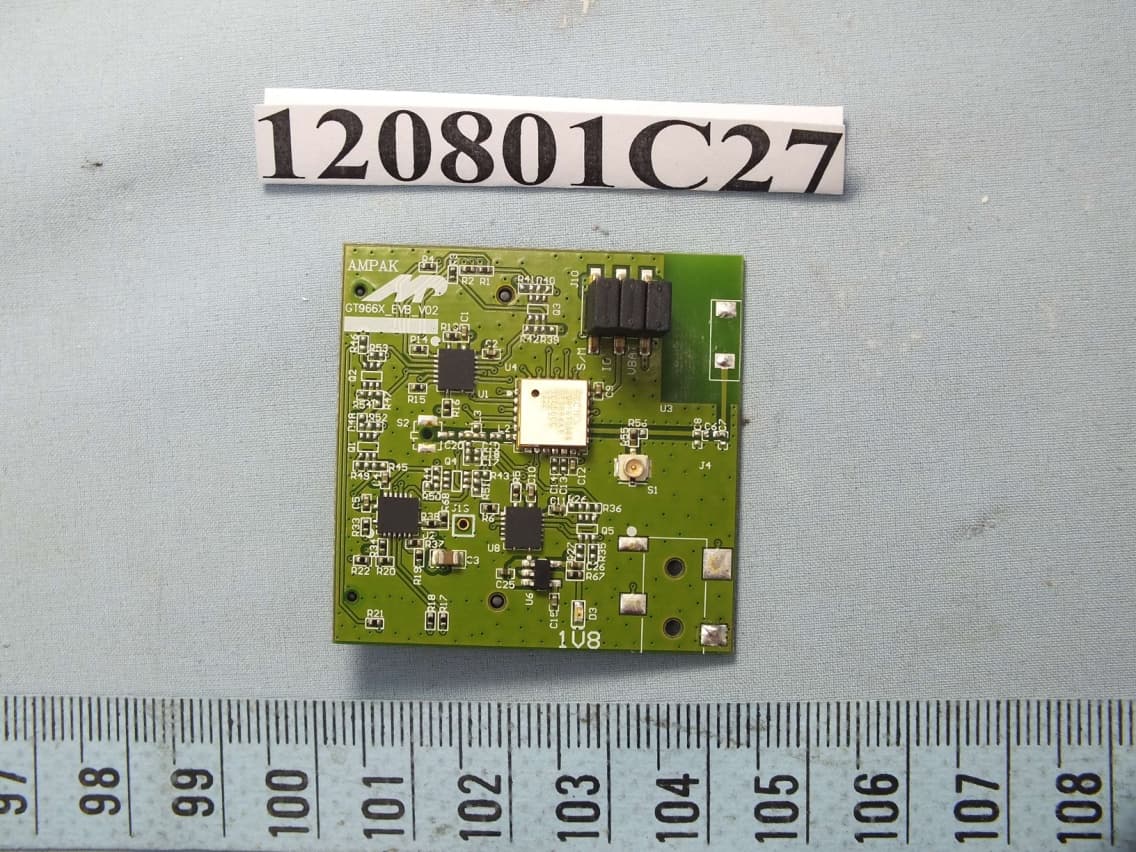
ATMLB401
Jul 14, 2013Bluetooth Module
Equipment Class
DSS - Part 15 Spread Spectrum Transmitter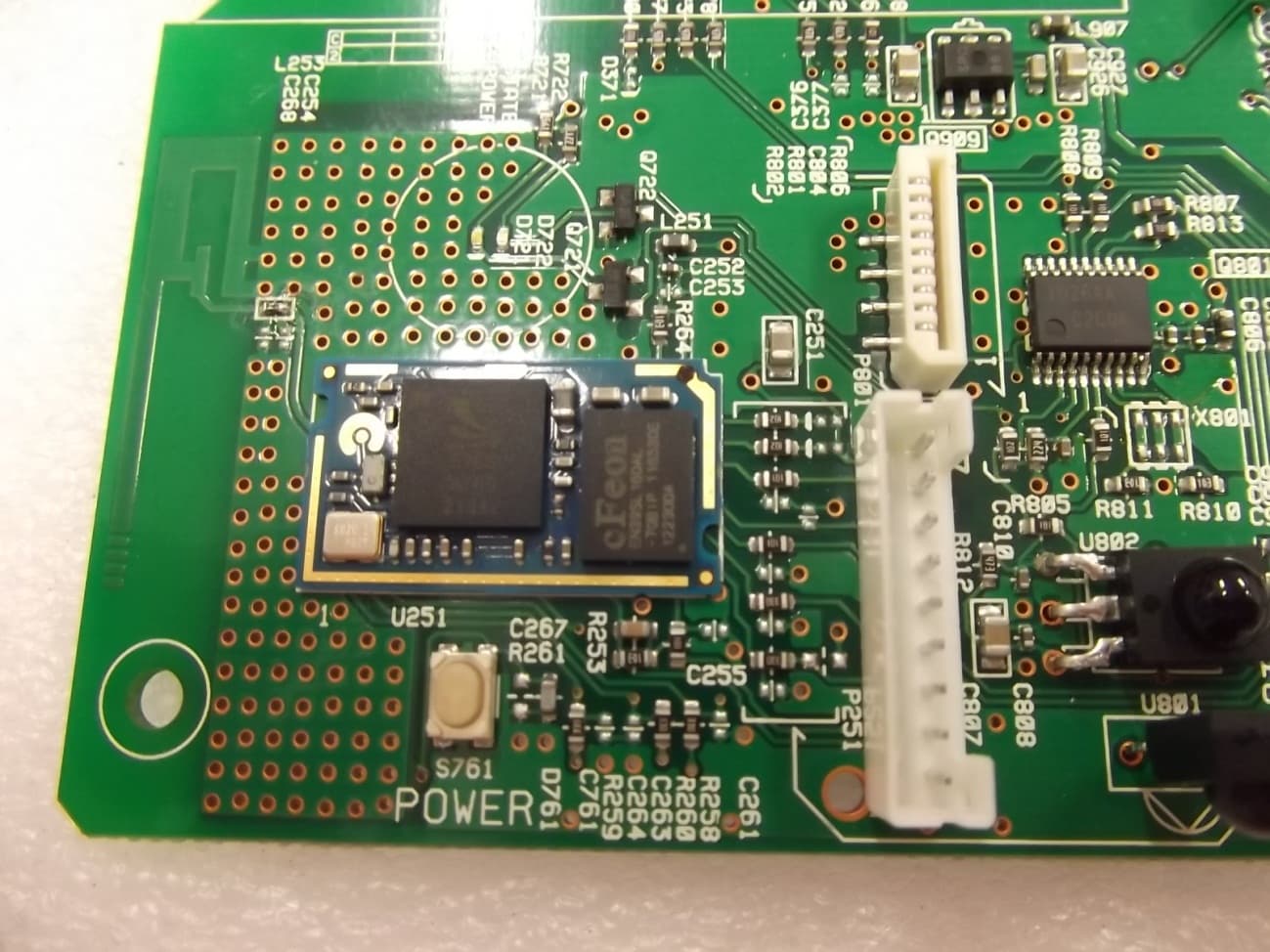
ATMLS3100
Sep 18, 2012BT Module
Equipment Class
DSS - Part 15 Spread Spectrum Transmitter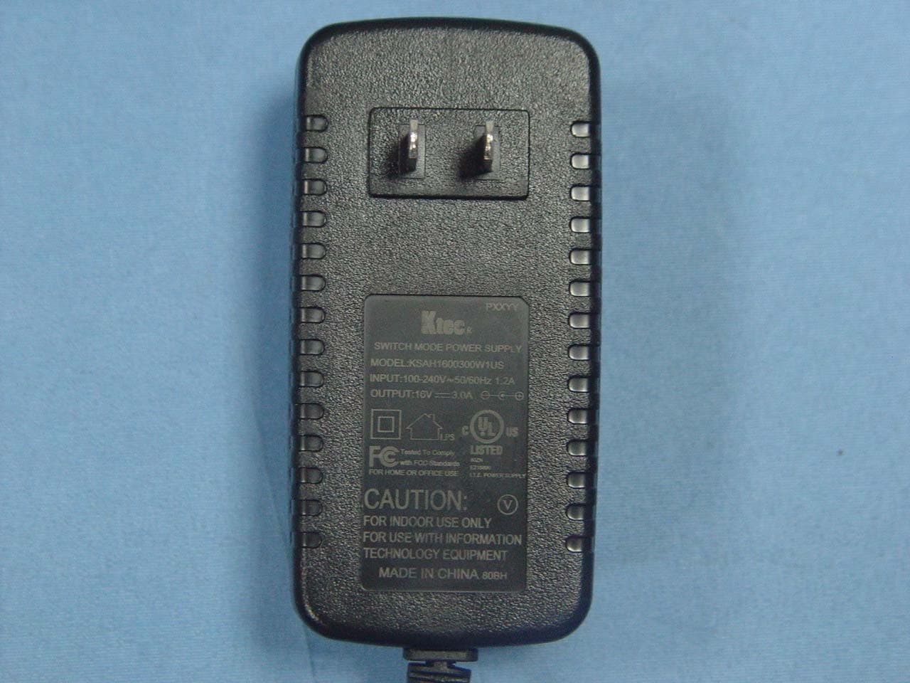
ATMABXN300
Oct 19, 2011Wireless Music System
Equipment Class
DTS - Digital Transmission System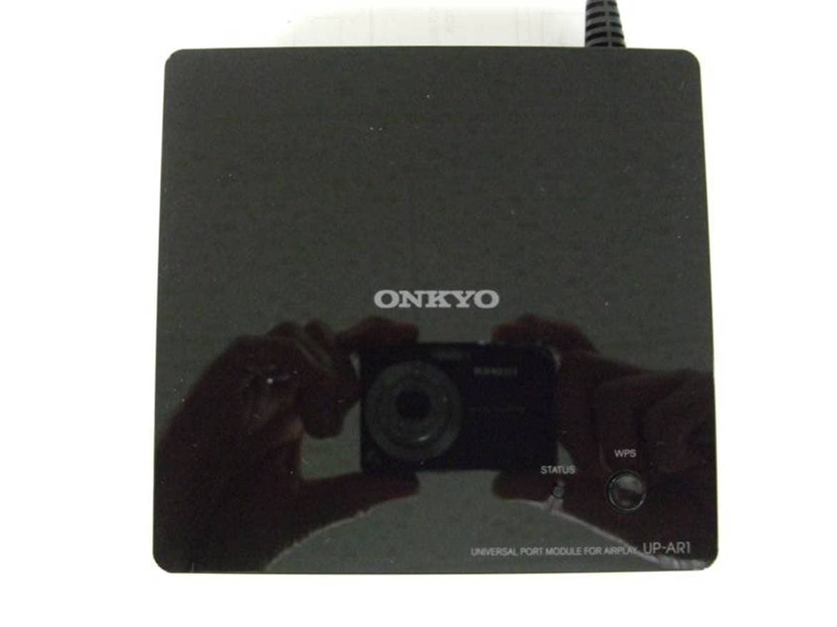
ATMUPAR1
Jul 09, 2011UNIVERSAL PORT MODULE FOR AIRPLAY
Equipment Class
JBP - Part 15 Class B Computing Device Peripheral