AX2EE2178Digital Wireless Camera System Receiver
Faurecia Clarion Electronics Co., Ltd.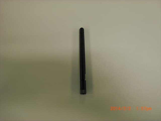
Click to zoom
Application Details
- Equipment Class
- DTS - Digital Transmission System
- Date of Grant
- Feb 17, 2014
- Application Purpose
- Original Equipment
- Date of Application
- Feb 04, 2014
- Equipment Note
- Digital Wireless Camera System Receiver
- Frequency Range
- 2412.00000000 - 2462.00000000
- Country
- Japan
Documents & Files
Document Text
Text extracted from the exhibit documents filed with the FCC. Open a document above to read the original.
Users Manual
Printed in Japan 2013/11 EE-2178 274-0513-01 •Thank you for purchasing this Clarion product. •Please fully read this Installation/Owner’s Manual before operating this equipment. •In accordance with FCC Rules and Regulations, Title 47, Part 15, Subpart C, this Clarion wireless local area network (WLAN) camera systems may experience momentary signal interruption due to RF interference and/or environmental surroundings. If continued interruption occurs, please check and/or adjust the antenna on the camera and receiver. SAFETY PRECAUTIONS When using this system, follow the precautions listed below. WARNING ●This device is a rear view camera intended for vehicle installation. Do not use it in any way other than its intended use. Doing so may result in smoke, fire, electric shock or injury. ●Drive slowly while reversing. ●Do not disassemble and/or modify the device. Doing so may result in accident, fire, electric shock or malfunction. ●Do not damage the camera cable. Moisture or water may get inside the camera through the damaged part, possibly resulting in a malfunction or fire. ●Never use the parts that are critical to the vehicle's safety* for mounting or grounding the device. * Nuts and bolts in the steering system, seat rails, brake system, fuel tank, etc. Doing so may result in loss of control, fire or traffic accident. ●Never drive looking solely at the monitor. This is an auxiliary device to supplement the driver's rear field of vision; it does not show all hazards or obstacles. Actual distances and perceptions may differ and video images may be delayed, so be sure to visually check safety while driving. Failure to do so creates the risk of hitting a person or object in the camera's blind spot, causing a serious accident. ●Do not use the device in a malfunctioning or abnormal state. If no image is displayed, smoke is emitted or there is a strange smell, stop using the device immediately. Continued use may result in an accident, fire or electric shock. ●Do not allow any water or foreign objects to get inside the device. If a foreign object or water gets inside the device, smoke or a strange smell is produced, or any other abnormality occurs, stop using the device immediately and consult the dealer where it was purchased. Continued use may result in an accident, fire or electric shock. ●Disconnect the negative terminal of the battery before connecting the cables. Failure to do so may result in electric shock or injury due to short-circuit. ●Route the cables to avoid high-temperature areas. The covering of the cables may melt, causing a short-circuit and resulting in an accident or fire. Pay particular attention when routing the cables inside the engine compartment. ●Mounting and removal of the device should be performed by a professional service technician. Failure to do so may result in an accident or fire. Contact the dealer where the device was purchased. ●After installing and connecting the device, check operation of the vehicle's electrical components*. * Brakes, lights, horn, hazard lamps, blinkers, etc. Malfunction may result in fire, electric shock or traffic accident. ●If mounting of the device requires making a hole in the chassis, check the position of the pipes, tanks, electrical wires, etc. and be sure to avoid interference or contact. Damage to the pipes etc. may lead to fire or malfunction. ●Route the cables and bundle them so that they do not interfere with driving operation. If a cable coils round the steering column, gear lever, brake pedals, etc., it may lead to an accident. ●Use the device on a DC12V negative earth vehicle. The device must not be used on a DC24V vehicle. Doing so may result in fire or malfunction. ●When connecting the cables to a vehicle equipped with air bags, do not route the cables where they will affect operation of the air bag system. If the air bags do not work properly, it may result in an accident or injury. ●Keep screws and other small parts out of the reach of small children. Small parts may be swallowed accidentally. If there is any suspicion that this may have happened, seek medical advice immediately. CAUTION ●The receiver is designed to be installed inside the vehicle's cabin. Do not install it in areas where it can get wet. Doing so may result in smoke, fire, electric shock or injury. ●Do not subject the receiver to strong impact such as dropping it or hitting it. This receiver utilizes precision electronic parts. Subjecting it to strong impact may result in malfunction or damage, leading to fire or electric shock. ●Remove the camera from the vehicle before using an automatic car wash (high pressure water). Failure to do so may result in the camera becoming detached or getting damaged. If water gets inside the camera, it may result in fire, electric shock or malfunction. ●Check the mounting screws occasionally and tighten any that have come loose. If the screws are loose, the device may become detached and fall off, hitting a passer-by and causing an accident. ●Follow the instructions in the manual when mounting and connecting the camera and receiver. Incorrect connection may result in fire or accident. ●After mounting the camera and receiver, check that the monitor image is a mirror image. Incorrect setup may mean that the monitor image is not horizontally flipped, resulting in accident. ●The rear-view monitor image has the same right-left inversion as your vehicle's rearview mirrors. Depending on the vehicle, the field and angle of view may differ. ●Be sure to use the supplied accessories and specified components. Using components other than those specified may lead to damage of the parts inside the device or the inability to secure them firmly, resulting in them becoming detached and leading to an accident or malfunction. ●After connecting the cables, secure them with clamps or insulating tape. If the cables come into contact with the chassis, they will fray and short-circuit, leading to an accident or fire. ●If a hole is made in the…
Text truncated - open the document above for the full version.
External Photos
Antenna Photo AN-DP005008 Antenna Photo IWX-1511RSXX with 3m Cable
ID Label/Location Info
2D
RF Exposure Info
UL Japan, Inc. Shonan EMC Lab. 1-22-3 Megumigaoka, Hiratsuka-shi, Kanagawa-ken, 259-1220 JAPAN Telephone : +81 463 50 6400 Facsimile : +81 463 50 6401 Applicant: Clarion Co., Ltd. T ype of Equipment : Digital W ireless C am era System Receiver Model No. : EE-2178 FCC ID: AX2EE2178 C larion C o., Ltd. declares that M odel : D igital W ireless C amera System R eceiver complies with FCC radiation exposure requirement specified in the FCC Rules 2.1091. The “EE-2178“ has 158.49 mW of conducted Peak Output power and 275.42 mW of EIRP. This kind of equipment is below SAR Threshold (KDB447498 D01 v05) The Following calculation is the reference data for 20cm distance. RF Exposure Calculations: The following information provides the minimum separation distance for the highest gain antenna provided with the “EE-2178“ as calculated from FCC OET Bulletin 65 Appendix A, Table (B) Limits for General Population / Uncontrolled Exposure. This calculation is based on the highest EIRP possible from the system, considering maximum power and antenna gain, and considering a 1.0mW/cm^2 uncontrolled exposure limit. The Friis formula used was: S = (P * G) / (4* π * r 2 ) Where P = 158.49 mW (M aximum peak output power) G = 1.74 Numerical Antenna gain; equal 2.40 dBi r =20.0 cm For: EE-2178S = 0.05479mW/cm 2 No. : 10006272S-B RF Ex posure / SAR Statement
Test Report
Test report No. : 10006272S-B Page : 2 of 53 Issued date : May 27, 2013 Revised date : February 19, 2014 FCC ID : AX2EE2178 UL Japan, Inc. Shonan EMC Lab. 1-22-3 Megumigaoka, Hiratsuka-shi, Kanagawa-ken, 259-1220 JAPAN Telephone : +81 463 50 6400 Facsimile : +81 463 50 6401 REVISION HISTORY Original Test Report No.: 10006272S-B Revision Test report No. Date Page revised Contents - (Original) 10006272S-B May 27, 2013 - - 1 10006272S-B February 19, 2014 4 Update of antenna information Test report No. : 10006272S-B Page : 3 of 53 Issued date : May 27, 2013 FCC ID : AX2EE2178 UL Japan, Inc. Shonan EMC Lab. 1-22-3 Megumigaoka, Hiratsuka-shi, Kanagawa-ken, 259-1220 JAPAN Telephone : +81 463 50 6400 Facsimile : +81 463 50 6401 Contents Page SECTION 1: Customer information ..................................................................................... 4 SECTION 2: Equipment under test (E.U.T.) ....................................................................... 4 SECTION 3: Test specification, procedures & results ......................................................... 5 SECTION 4: Operation of E.U.T. during testing ................................................................. 7 SECTION 5: Radiated emission ........................................................................................... 9 SECTION 6: Out of band emissions (Antenna port conducted) ....................................... 11 SECTION 7: 6dB bandwidth & Occupied bandwidth (99%) ........................................... 11 SECTION 8: Maximum peak output power ...................................................................... 11 SECTION 9: Peak power density........................................................................................ 11 Contents of APPENDIXES ................................................................................................... 12 APPENDIX 1: Data of Radio tests ...................................................................................... 13 APPENDIX 2: Test instruments ......................................................................................... 49 APPENDIX 3: Photographs of test setup ........................................................................... 50 Test report No. : 10006272S-B Page : 4 of 53 Issued date : May 27, 2013 Revised date : February 19, 2014 FCC ID : AX2EE2178 UL Japan, Inc. Shonan EMC Lab. 1-22-3 Megumigaoka, Hiratsuka-shi, Kanagawa-ken, 259-1220 JAPAN Telephone : +81 463 50 6400 Facsimile : +81 463 50 6401 SECTION 1: Customer information Company Name : Clarion Co., Ltd. Address : 7-2 Shintoshin, Chuo-ku, Saitama-shi, Saitama, 330-0081 Japan Telephone Number : +81-48-601-4121 Facsimile Number : +81-48-601-3802 Contact Person : Masahiko Shibata SECTION 2: Equipment under test (E.U.T.) 2.1 Identification of E.U.T. Type of Equipment : Digital Wireless Camera System Receiver Model Number : EE-2178 Serial Number : Refer to 4.2 in this report. Rating : 12VDC (10.8V - 15.6V) Country of Mass-production : Japan Condition of EUT : Production prototype (Not for Sale: This sample is equivalent to mass-produced items.) Receipt Date of Sample : March 23 and April 9, 2013 Modification of EUT : No modification by the test lab. 2.2 Product description Model: EE-2178 (referred to as the EUT in this report) is a Digital Wireless Camera System Receiver. Clock frequency(ies) in the system : 13.33MHz, 27MHz Radio specification: Equipment type : Transceiver Frequency of operation : 2412-2462MHz Bandwidth & Channel spacing : 20MHz & 5MHz Type of modulation : DSSS, OFDM ITU code : D1D, G1D Operation temperature range : -20 to +70 deg.C Antenna information: Antenna 2dBi antenna 5dBi antenna + 3m Cable Antenna type Dipole Dipole Antenna connector type *1) Reverse-SMA with connector housing to limit the connection Antenna gain 2.4dBi 2dBi (5dBi+Cable loss 3dB) *1) Each antenna connection is the limited by Reverse-SMA with the connector housing. High gain antenna cannot be connected to EUT directly. FCC 15.31 (e) The EUT provides stable voltage (DC3.3V) constantly to the wireless transmitter regardless of input voltage. Therefore, this EUT complies with the requirement. FCC 15.203 The EUT has a unique coupling/antenna connector (Reverse SMA). Therefore the equipment complies with the requirement. Test report No. : 10006272S-B Page : 5 of 53 Issued date : May 27, 2013 FCC ID : AX2EE2178 UL Japan, Inc. Shonan EMC Lab. 1-22-3 Megumigaoka, Hiratsuka-shi, Kanagawa-ken, 259-1220 JAPAN Telephone : +81 463 50 6400 Facsimile : +81 463 50 6401 SECTION 3: Test specification, procedures & results 3.1 Test specification Test specification : Test specification: FCC Part 15 Subpart C: 2012, final revised on December 27, 2012 and effective January 28, 2013 Title : FCC 47CFR Part15 Radio Frequency Device Subpart C Intentional Radiators Section 15.207 Conducted limits Section 15.209 Radiated emission limits, general requirements Section 15.247 Operation within the bands 902-928MHz, 2400-2483.5MHz, and 5725-5850MHz 3.2 Procedures & Results Item Test Procedure *1) SpecificationRemarks DeviationWorst Margin Results Conducted emission ANSI C63.10:2009 FCC 15.207 - N/A *2) N/A N/A 6dB bandwidth ANSI C63.10:2009 FCC 15.247 (a)(2) ConductedN/A * See data Complied Maximum peak output power ANSI C63.10:2009 FCC 15.247 (b)(3) ConductedN/A Complied Out of band emission & Restricted band edges ANSI C63.10:2009 FCC 15.109, 15.247 (d) & 15.209 Conducted / Radiated N/A 1.8dB Freq.: 2483.500MHz Polarization: Horizontal Detection: Peak Mode: Tx 2462MHz, IEEE 802.11b Antenna: 5dBi antenna Complied Power density ANSI C63.10:2009 FCC 15.247 (e) ConductedN/A * See data Complied Note: UL Japan’s EMI Work Procedures No.13-EM-W0420 and 13-EM-W0422. *1) These tests were also referred to KDB 558074 (FCC), "Guidance for Performing Compliance Measurements on Digital Transmission Systems (DTS) Operating Under §15.247”. *2) The test is not applicable since the EUT has no AC mains. 3.3 Addition…
Text truncated - open the document above for the full version.
Test Setup Photos
UL Japan, Inc. Shonan EMC Lab. 1-22-3 Megumigaoka, Hiratsuka-shi, Kanagawa-ken, 259-1220 JAPAN Telephone : +81 463 50 6400 Facsimile : +81 463 50 6401 APPENDIX 3: Photographs of test setup Radiated emission 2dBi antenna Front Rear (below 1GHz) Rear (above 1GHz Test Report No.: 10006272S-B 50 of 53 UL Japan, Inc. Shonan EMC Lab. 1-22-3 Megumigaoka, Hiratsuka-shi, Kanagawa-ken, 259-1220 JAPAN Telephone : +81 463 50 6400 Facsimile : +81 463 50 6401 5dBi antenna + 3m Cable Front Rear (below 1GHz) Rear (above 1GHz Test Report No.: 10006272S-B 51 of 53 UL Japan, Inc. Shonan EMC Lab. 1-22-3 Megumigaoka, Hiratsuka-shi, Kanagawa-ken, 259-1220 JAPAN Telephone : +81 463 50 6400 Facsimile : +81 463 50 6401 Pre-check of the worst position 2dBi Antenna Antenna Module X-axis X-axis Y-axis Y-axis Z-axis Test Report No.: 10006272S-B 52 of 53 UL Japan, Inc. Shonan EMC Lab. 1-22-3 Megumigaoka, Hiratsuka-shi, Kanagawa-ken, 259-1220 JAPAN Telephone : +81 463 50 6400 Facsimile : +81 463 50 6401 5dBi Antenna Antenna Module X-axis X-axis Y-axis Y-axis Z-axis END OF REPORT Test Report No.: 10006272S-B 53 of 53
Contact Information
Applicant
Makoto Okubo
Technical Contact
UL Japan, Inc.Toyokazu Imamura
[email protected]81-463-50-6400
1-22-3 Megumigaoka, Hiratsuka-shi · Kanagawa-ken · Japan
Test Firm
UL Japan, Inc. Shonan EMC EMC Lab.Tetsuya Hashimoto
Technical Specifications
| # | Rule Parts | Frequency Range | Power Output |
|---|---|---|---|
| 1 | 15C | 2.41 GHz - 2.46 GHz | 158.50 mW |
Other Applications from Faurecia Clarion Electronics Co., Ltd.
AX2P2601
Aug 26, 2026Car Audio
Equipment Class
DSS - Part 15 Spread Spectrum TransmitterAX2P2301
Apr 08, 2024Car Audio
Equipment Class
DTS - Digital Transmission System
AX277S0
Feb 01, 2021Car Audio
Equipment Class
DSS - Part 15 Spread Spectrum Transmitter
AX2QY5153
Aug 19, 2015Navigation Unit, Display Audio Unit
Equipment Class
DTS - Digital Transmission System
AX2QY5099
May 27, 2015Navigation Unit
Equipment Class
DTS - Digital Transmission System