AXI11144630MOBILE TRANSCEIVER
Vertex Standard USA, Inc.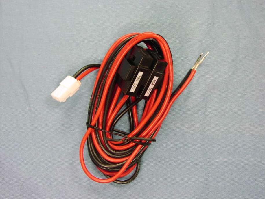
Click to zoom
Application Details
- Equipment Class
- TNB - Licensed Non-Broadcast Station Transmitter
- Date of Grant
- Oct 28, 2013
- Application Purpose
- Original Equipment
- Date of Application
- Oct 28, 2013
- Equipment Note
- MOBILE TRANSCEIVER
- Frequency Range
- 456.00000000 - 470.00000000
- Company
- Vertex Standard USA, Inc.
- Country
- United States
Documents & Files
Document Text
Text extracted from the exhibit documents filed with the FCC. Open a document above to read the original.
Users Manual
EVX-5300 EVX-5400 Operating Manual prOgraMMable FunctiOns/Features 6 Programmable Function Keys 2-Tone Encode/Decode ø 1 5-Tone Encode/Decode ø 1 MDC-1200 ® Encode/Decode ø 1 Horn Alert PA (Public Address) Scan Group Scan ø 2 Dual Watch FM-Scan ( Follow-Me Scan ) TA Scan Encryption ø 1 Privacy VOX Talk Around Emergency Lone Worker TX Save Disable Direct Channel Entry ø 2, 3 Code Up/Down ø 2 Code Set ø 2 Speed Dial ø 2, 3 DTMF Code Set ø 2, 3 ID Check ø 2 ARTS TM /ARTS II TM ( Auto Range Transpond System ) ø 1 ø 1: Analog mode only ø 2: EVX-5400 only ø 3: R equires Optional MH-75 A8J eVX-5300eVX-5400 FCC ID: AXI11144630 IC: 10239A-11144630 Vertex Standard LMR, Inc. Unsafe Radiation Distance Congratulations! You now have at your fingertips a valuable communications tool: a Vertex Stan- dard two-way radio! Rugged, reliable and easy to use, your Vertex Standard radio will keep you in constant touch with your colleagues for years to come, with negli- gible maintenance downtime. Please take a few minutes to read this manual carefully. The information presented here will allow you to derive maximum performance from your radio. We’re glad you joined the Vertex Standard team. Call on us anytime, because com- munications is our business. Let us help you get your message across. Notice ! There are no owner-serviceable parts inside the transceiver. All service jobs must be referred to an authorized Vertex Standard Service Representative. Consult your Authorized Vertex Standard dealer for installation of optional accessories. Safety/WarNiNg iNformatioN WARNING - DO NOT operate the EVX-5300/-5400 radio when any person(s) (bystanders) outside the vehicle are within the distances shown in the chart at the bottom of this section. Safety Training information: Antennas used for this transmitter must not exceed an antenna gain of 0 dBi. The radio must be used in vehicle-mount configurations with a maxi- mum operating duty cycle not exceeding 50 %, in typical Push-to-Talk con- figurations. This radio is restricted to occupational use, work related operations only where the radio operator must have the knowledge to control the exposure limits of passengers and bystanders by maintaining the minimum separa- tion distance shown below. Failure to observe these restrictions will result in exceeding the FCC RF exposure limits. Antenna Installation: For rear deck trunk installation, the antenna must be located at least the fol- lowing distance away from rear-seat passengers in order to comply with the FCC RF exposure requirements. For roof top installations, the antenna must be placed in the center of the roof. VHF ModelUHF Model 2.9 Feet ( 0.89 m ) 2.1 Feet ( 0.64 m ) FCC ID: AXI11144630 IC: 10239A-11144630 Vertex Standard LMR, Inc. EVX-5300/-5400 OpErating Manual1 The EVX-5300/-5400 series are full-featured Digital/Analog transceiver designed for flexible mobile and base station business communications in the VHF/UHF Land Mobile bands. This transceiver designed for reliable business communica- tions in a wide variety of applications with a wide range of operating capability provided by their leading-edge design. The EVX-5300/-5400 operates using the TDMA protocol for spectrum and power efficiency and lower total equipment cost compared to FDMA. Digital eliminates noise and static from voice transmit to only deliver the intended voice message crisply and clearly. The EVX-5300/-5400 feature the AMBE+2™ vocoder for en- hanced voice quality. This transceiver allows up to 8 memory channels. Important channel frequency data is stored in the flash memory on the CPU, and is easily programmable by a Vertex Standard licensed dealers using a personal computer with Vertex Standard Programming equipment FIF-12 USB Programming Interface and CT-104A Con- nection Cable for FIF-12 and CE142 Software. Or, once programmed, cloning cable CT-4 can be used to program portable to portable directly. The pages which follow will detail the many advanced features provided in the EVX-5300/-5400 series transceiver. After reading this manual, you may wish to consult with your Network Administrator regarding precise details of the configu- ration of this equipment for use in your application. For North American Users Regarding 406 MHz Guard Band The U.S. Coast Guard and National Oceanographic and Atmospheric Administration have requested the cooperation of the U.S. Federal Communications Commission in preserving the integrity of the protected frequency range 406.0 to 406.1 MHz, which is reserved for use by distress beacons. Do not attempt to program this apparatus, under any circumstances, for operation in the frequency range 406.0 - 406.1 MHz if the apparatus is to be used in or near North America. IntroductIon EVX-5300EVX-5400 FCC ID: AXI11144630 IC: 10239A-11144630 Vertex Standard LMR, Inc. EVX-5300/-5400 OpErating Manual2 WarnIng! Fcc rF ExposurE rEquIrEmEnts THIS DEVICE COMPLIES WITH PART 15 OF THE FCC RULES. OPERA- TION IS SUBJECT TO THE FOLLOWING TWO CONDITIONS: (1) THIS DEVICE MAY NOT CAUSE HARMFUL INTERFERENCE, AND (2) THIS DEVICE MUST ACCEPT ANY INTERFERENCE RECEIVED, INCLUDING INTERFERENCE THAT MAY CAUSE UNDESIRED OPERATION. THE GRANTEE IS NOT RESPONSIBLE FOR ANY CHANGES OR MODIFI- CATIONS NOT EXPRESSLY APPROVED BY THE PARTY RESPONSIBLE FOR COMPLIANCE. SUCH MODIFICATIONS COULD VOID THE USER’S AUTHORITY TO OPERATE THE EQUIPMENT. This equipment has been tested and found to comply with the limits for a Class B digital device, pursuant to part 15 of the FCC Rules. These limits are designed to provide reasonable protection against harmful interference in a residential installa- tion. This equipment generates, uses and can radiate radio frequency energy and, if not installed and used in accordance with the instructions, may cause harmful interference to radio communications. However, there is no guarantee that inter- ference will not occur in a particular installation. If this equipment doe…
Text truncated - open the document above for the full version.
Cover Letter(s)
FCC ID: AXI11144630 October 2, 2013 Timco Engineering, Inc. 849 NW State Road 45 P.O. Box 370 Newberry, Florida 32669 Subject: Extended Frequencies Justification. Gentlemen; The EVX-5300-G6-25/EVX-5400-G6-25 Mobile Transceiver was designed to operate in the frequency band 403-470 MHz. To aid equipment authorization in other countries which accept the United States FCC Grant for Certification, Vertex Standard LMR, is requesting that the FCC lists the frequencies 403-470 MHz on the FCC Grant. For the FCC’s Rule Parts 90 applications, this radio is used in systems by Federal and Public Safety agencies including Police, Fire, and Emergency Medical Services, etc. as indicated in the table below. Equipment programming is the responsibility of Authorized Service Personnel. Also, the radio complies with 47 CFR Part 90.203(e), in that the operator cannot directly program the transmit frequencies using the normally accessible external controls. Per the FCC’s KDB634817 guidance, as an alternative to listing the exact frequencies, we acknowledge that it’s a violation of the FCC Rules if this device operates on unauthorized frequencies. Frequency Range (MHz) Part 90 Part 22 Part 74 Federal Grant Notes Emission Designator Rule Part 90 403-406 x x E F, BD 7K 60 F1D/F1E/F1W/FXE/FXD, 11K0F3E 406.1-410 x x E F, BD “”” 410-420 x x E F, BD “”” 450-454 x x E F, BD “”” 454-455* E F, BD “”” 455-456* x E F, BD “”” 456-460 x x E F, BD “”” 460-462.5375 x E F, BD “”” 462.7375-467.5375 x E F, BD “”” 467.7375-470 x x EF, BD “”” * Canada Sincerely, Yukimasa Tomita Executive Manager Vertex Standard LMR, Inc.
Cover Letter(s)
September 6, 2013 Federal Communications Commission Authorization and Evaluation Division, 7435 Oakland Mills Road Columbia, MD 21046 USA Re: FCC ID: AXI11144630 Model: EVX-5300-G6-25 / EVX-5400-G6-25 Gentlemen: Part 15.19 Compliance Statement is placed on the rear of case. Sincerely, Vertex Standard LMR, Inc. Yukimasa Tomita Executive Manager
Cover Letter(s)
September 6, 2013 Federal Communications Commission Authorization and Evaluation Division, 7435 Oakland Mills Road Columbia, MD 21046 USA Re: FCC ID: AXI11144630 Model: EVX-5300-G6-25 / EVX-5400- G6-25 Gentlemen: A. Part 15.21 Compliance Statement Drawing: B. Part 15.21 Compliance StatementDrawing Location: IN OPERATING MANUAL (location on inside last page) Sincerely, Vertex Standard LMR, Inc. Yukimasa Tomita Executive Manager Part 15.21: Changes or modifications to this device not expressly approved by Vertex Standard could void the user’s authorization to operate this device. 18mm 117mm
Cover Letter(s)
September 6, 2013 Federal Communications Commission Authorization and Evaluation Division, 7435 Oakland Mills Road Columbia, MD 21046 USA Re: FCC ID: AXI11144630 Model: EVX-5300-G6-25 / EVX-5400-G6-25 Gentlemen: The equipment meets the requirements of the FCC Rules, Part 90.203(e) and (g), as applicable. Programming of this product’s transmit frequencies can be performed only by the manufacturer or by service or maintenance personal. The operator cannot be program transmit frequencies using the equipment’s external operation controls. Sincerely, Vertex Standard LMR, Inc. Yukimasa Tomita Executive Manager
Cover Letter(s)
September 6, 2013 Federal Communications Commission EQUIPMENT APPROVAL SERVICES P. O. Box 358315 Pittsburgh, PA 15251-5315 Attention: Authorization and Evaluation Division Reference: FCC ID: AXI11144630 Model: EVX-5300-G6-25 / EVX-5400-G6-25 Pursuant to Sections 0.457 (d)(1)(ii) and 0.459 of the Commission’s Rules, the Applicant hereby requires confidential treatment of some of the information accompanying this Application, as listed below: ・ Block Diagram ・ Schematics These materials contain trade secrets and proprietary information not customarily released to the public. The public disclosure of these matters might be harmful to the Applicant and provide unjustified benefits to its competitors. The Applicant understands that pursuant to Rule 0.457 (d)(1)(ii), disclosure of the Application and all accompanying documentation will not be made before the date of Grant for this Application. Sincerely, Vertex Standard LMR, Inc. Yukimasa Tomita Executive Manager
External Photos
FCC ID: AXI11144630 IC: 10239A-11144630 Vertex Standard LMR, Inc. Front view (EVX-5300) Front view (EVX-5400) FCC ID: AXI11144630 IC: 10239A-11144630 Vertex Standard LMR, Inc. Rear view Left view FCC ID: AXI11144630 IC: 10239A-11144630 Vertex Standard LMR, Inc. Right view Top view FCC ID: AXI11144630 IC: 10239A-11144630 Vertex Standard LMR, Inc. Bottom view Microphone FCC ID: AXI11144630 IC: 10239A-11144630 Vertex Standard LMR, Inc. DC Power Cable
ID Label/Location Info
EVX-5300-G6-25 / EVX-5400-G6-25 EVX-5300-G6-25 / EVX-5400-G6-25 LABEL DRAWINGLABEL DRAWING Vertex Standard LMR, Inc.Vertex Standard LMR, Inc. ID / Part 15.19 and CAUTION drawings ID drawing Part 15.19 and CAUTION drawings Label location 2013. 9.6 2013. 9.6 EVX-5300-G6-25 4N3I250008 SER.NO. Model:EVX-5300-G6-25 FCC ID: AXI11144630 IC: 10239A-11144630 VERTEX STANDARD LMR,INC. MADE IN CHINA 788026138715 EVX-5400-G6-25 4N3I250013 SER.NO. Model:EVX-5400-G6-25 FCC ID: AXI11144630 IC: 10239A-11144630 VERTEX STANDARD LMR,INC. MADE IN CHINA 788026138746
Internal Photos
FCC ID: AXI11144630 IC : 10239A-11144630 Vertex Standard LMR, Inc. Removed top cover Removed Shield Cover FCC ID: AXI11144630 IC : 10239A-11144630 Vertex Standard LMR, Inc. Side-A of MAIN-Unit with shield case Side-A of MAIN-Unit without shield case FCC ID: AXI11144630 IC : 10239A-11144630 Vertex Standard LMR, Inc. Side-B of MAIN-Unit with shield case Side-B of MAIN-Unit without shield case FCC ID: AXI11144630 IC : 10239A-11144630 Vertex Standard LMR, Inc. Inside of FRONT panel with Unit and SP (EVX-5300) Side-A of FRONT-Unit and Rubber Key top (EVX-5300) Side-B of FRONT-Unit (EVX-5300) FCC ID: AXI11144630 IC : 10239A-11144630 Vertex Standard LMR, Inc. Inside of FRONT panel with Unit and SP (EVX-5400) FCC ID: AXI11144630 IC : 10239A-11144630 Vertex Standard LMR, Inc. Side-A of FRONT-Unit and Rubber Key top (EVX-5400) Side-B of FRONT-Unit (EVX-5400) FCC ID: AXI11144630 IC : 10239A-11144630 Vertex Standard LMR, Inc. Side-A of FRONT-Unit Without LCD (EVX-5400) Side-A of LCD (EVX-5400) FCC ID: AXI11144630 IC : 10239A-11144630 Vertex Standard LMR, Inc. Side-B of LCD (EVX-5400) Inside of FRONT panel (EVX-5300) Inside of FRONT panel EVX-5400) FCC ID: AXI11144630 IC : 10239A-11144630 Vertex Standard LMR, Inc. Inside of chassis FCC ID: AXI11144630 IC : 10239A-11144630 Vertex Standard LMR, Inc. Inside of microphone
Operational Description
FCC ID: AXI11144630 IC: 10239A-11144630 Circuit Description Vertex Standard LMR, Inc. EVX-5300/5400 (UHF) Circuit Description 1. Receiver System 1-1. Front-end RF amplifier Incoming RF signal from the antenna passes through the Low-pass filter, antenna switching diode D1014, D1016 (both JDP2S12CR), and the 1st RF attenuator Q1037 (SKY12338), and then removed undesired frequencies by the varactor tuned band-pass filter D1022, D1023 (all 1SV323). The filtered RF signal is amplified by Q1045 (2SC3356) and then passes through the Band-pass filter D1026, D1027 and D1061 (all 1SV323) , 2nd RF attenuator Q1050 (SKY12338) and then applied to the 1st mixer Q1053 (AK1220). 1-2. First Mixer The RF signal is mixed with the 1st local signal between 352.15 MHz and 419.15 MHz in the 1st mixer Q1053(AK1220), to produce 50.85 MHz 1st IF signal. The 1st local signal is generated by the VCO, which consists of Q1055 (2SK508), varactor diodes D1029, D1032, D1036, and D1037 (1SV279,1SV280). The 1st local signal is supplied to the 1st mixer Q1053(AK1220) through the buffer amplifier Q1064(2SC5006) and Q1066 (2SC5226). 1-3. IF Amplifier & Demodulator The 1st IF signal is applied to the monolithic crystal filter XF1001 to strip away all but the desired signal, and then supplied to the custom IC Q1070 ( RFIC ) through the IF amplifier Q1068 (2SC5226). The custom IC Q1070 ( RFIC ) converts the 1st IF signal into the Base Band signal. The Base Band signal from the custom IC Q1070 ( RFIC ) is applied to another custom IC Q1001 (OMAP), which is demodulated by the Digital Signal Processor. 1-4. Audio amplifier The demodulated signal from the custom IC Q1001 (OMAP) is applied to another custom IC Q1044 ( PMAIC ). The custom IC Q1044 ( PMAIC ) convert to analog signal. The output signal from the custom IC Q1044 ( PMAIC ) is applied to the AF amplifier which is constructed Q1015(NJM12902) and Q1027(TDA1519CTH). The output of Q1027(TDA1519CTH) drive a front panel speaker or external speaker that is connected microphone jack J1004. FCC ID: AXI11144630 IC: 10239A-11144630 Circuit Description Vertex Standard LMR, Inc. 2. Transmitter System 2-1. MIC Amplifier and modulator The speech signal from external microphone which connected J2001 (EVX-5300) or J3001 (EVX-5400) is supplied to AF amplifier Q2005 (NJM2125 / EVX-5300) or Q3010 (NJM2125 / EVX-5400). The output signal is supplied the custom IC Q1044 ( PMAIC ), which is amplified the speech signal. The amplified speech signal from the custom IC Q1044 ( PMAIC ) is supplied to another custom IC Q1001 ( OMAP ), which process the speech signal by the Digital Signal Processor. The processed speech signal from the custom IC Q1001 (OMAP) is supplied to the modulator section of the custom IC Q1070 ( RFIC ), which modulates the speech signal into the FM or digital signal. 2-2. Drive and Final Amplifier Stages The modulated signal from the custom IC Q1070 ( RFIC ) is buffered by Q1061 (2SK3077) and amplified by Q1052 (RD01MUS1). The Low-level signal is then applied to Power Module Q1046 (RA30H3847M1A) for final amplification up to 25 watts output power. The transmit signal then passes through the antenna switch D1018, D1019 (both MA4P959) and is low pass filtered to suppress away harmonic spurious radiation before delivery to the antenna. 2-3. Automatic Transmit Power Control The output power of Power Module is detected by CM coupler, forward power is detected by D1020 (HSM88AS) and is input to comparator Q1074 (ADM8566ARM), The comparator Q1074 (ADM8566ARM) compares detected voltage of forward power and power control voltage from custom IC Q1070 (RFIC), makes output power stable by controlling the bias voltage RF amplifier Q1052 (RD01MUS1). Additionally, output voltage of operational amp Q1043 (ADM8566ARM) is supplied to Power Module .There are 4levels of output power (Hi, Lo3, Lo2 and Lo1) it is controlled by the Q1070 (RFIC). Reflection power is detected by D1021 (HSM88AS), Automatic transmission power control circuit protect equipment. For example, when the antenna is not connected. FCC ID: AXI11144630 IC: 10239A-11144630 Circuit Description Vertex Standard LMR, Inc. 3. PLL Frequency Synthesizer The frequency synthesizer consists of VCO, TCXO (X1002), and the custom IC Q1070 ( RFIC ). The output frequency from TCXO is 19.2 MHz and the tolerance is ±1.5 ppm in the temperature range –22 °F to +140 °F (–30 °C to +60 °C). 3-1. VCO (Voltage Controlled Oscillator) While the radio is receiving, the RX oscillator Q1055 (2SK508) generates a programmed frequency between 352.15 and 419.15 MHz as 1st local signal. While the radio is transmitting, the TX oscillator Q1054 (2SK508) generates a frequency between 403 and 470 MHz . The output from oscillator is amplified by buffer amplifier Q1064 (2SC5006) and then is divided, one is feed back to the PLL Circuit in the custom IC Q1070 ( RFIC ). The other one is supplied to the 1st mixer Q1053 (AK1220) in case of the reception. In the transmission, the output is modulated to the FM (or digital) in the custom IC Q1070 ( RFIC ), and then supplied to the transmitter section described previously. 3-2. VCV (Varactor Control Voltage) Control The tuning voltage (VCV) of the VCO establishes the lock range of VCO by controlling the cathode of varactor diode (D1029, D1032, D1036, D1037 for receiving, and D1028, D1031, D1034, D1035 for transmitting: 1SV279) from the custom IC Q1070 ( RFIC ). 3-3. PLL The main constitution product of the PLL is equipped all with in the custom IC Q1070 ( RFIC ), so that all processing regarding the frequency control is performed in the custom IC Q1070 ( RFIC ).
Parts List/Tune Up Info
FCC ID: AXI11144630 IC: 10239A-11144630 Alignment Vertex Standard LMR, Inc. EVX-5300 / 5400 (UHF) Alignment FCC ID: AXI11144630 IC: 10239A-11144630 Alignment Vertex Standard LMR, Inc. FCC ID: AXI11144630 IC: 10239A-11144630 Alignment Vertex Standard LMR, Inc. FCC ID: AXI11144630 IC: 10239A-11144630 Alignment Vertex Standard LMR, Inc. FCC ID: AXI11144630 IC: 10239A-11144630 Alignment Vertex Standard LMR, Inc. FCC ID: AXI11144630 IC: 10239A-11144630 Alignment Vertex Standard LMR, Inc. FCC ID: AXI11144630 IC: 10239A-11144630 Alignment Vertex Standard LMR, Inc. FCC ID: AXI11144630 IC: 10239A-11144630 Alignment Vertex Standard LMR, Inc. FCC ID: AXI11144630 IC: 10239A-11144630 Alignment Vertex Standard LMR, Inc. FCC ID: AXI11144630 IC: 10239A-11144630 Alignment Vertex Standard LMR, Inc.
Parts List/Tune Up Info
1 FCC ID: AXI11144630/IC: 10239A-11144630 EVX-5300 / 5400 Series (UHF)Semi-Conductor Parts List Address Parts Code Device NameDescriptionTYP VAL MAIN-UNIT D 1001 G2071378 Zener DiodeUDZS27B D 1002 G2071378 Zener DiodeUDZS27B D 1003 G2071378 Zener DiodeUDZS27B D 1004 G2071378 Zener DiodeUDZS27B D 1005 G2071378 Zener DiodeUDZS27B D 1006 G2071378 Zener DiodeUDZS27B D 1007 G2071378 Zener DiodeUDZS27B D 1008 G2071378 Zener DiodeUDZS27B D 1009 G2071378 Zener DiodeUDZS27B D 1010 G2071378 Zener DiodeUDZS27B D 1011 G2071378 Zener DiodeUDZS27B D 1012 G2071378 Zener DiodeUDZS27B D 1013 G2071378 Zener DiodeUDZS27B D 1014 G2071446 DiodeJDP2S12CR(TE85L.M) D 1015 G2071322 DiodeSM8S24AHE3/2D D 1016 G2071446 DiodeJDP2S12CR(TE85L.M) D 1018 G2071320 DiodeMA4P959 D 1019 G2071320 DiodeMA4P959 D 1020 G2070170 DiodeHSM88AS TR-E D 1021 G2070170 DiodeHSM88AS TR-E D 1022 G2071006 Diode1SV323(TPH3.F) D 1023 G2071006 Diode1SV323(TPH3.F) D 1024 G2070634 Diode1SS400 TE61 D 1025 G2070910 Zener DiodeUDZS TE-17 5.6B D 1026 G2071006 Diode1SV323(TPH3.F) D 1027 G2071006 Diode1SV323(TPH3.F) D 1028 G2070618 Diode1SV279(TPH3.F) D 1029 G2070618 Diode1SV279(TPH3.F) D 1031 G2070618 Diode1SV279(TPH3.F) D 1032 G2070618 Diode1SV279(TPH3.F) D 1034 G2070618 Diode1SV279(TPH3.F) D 1035 G2070618 Diode1SV279(TPH3.F) D 1036 G2070618 Diode1SV279(TPH3.F) D 1037 G2070618 Diode1SV279(TPH3.F) D 1040 G2070914 Zener DiodeUDZS TE-17 16B D 1041 G2071380 Zener DiodeKDZ5.1B D 1042 G2070174 DiodeDAN222 TL D 1043 G2070178 DiodeDA221 TL D 1044 G2070942 Diode1SV305(TPH3) D 1045 G2070942 Diode1SV305(TPH3) D 1046 G2070850 DiodeRB751S-40TE61 D 1047 G2070850 DiodeRB751S-40TE61 D 1048 G2070850 DiodeRB751S-40TE61 D 1049 G2070850 DiodeRB751S-40TE61 D 1050 G2070850 DiodeRB751S-40TE61 D 1051 G2070178 DiodeDA221 TL D 1052 G2070910 Zener DiodeUDZS TE-17 5.6B D 1055 G2071004 Zener DiodeEDZ TE-61 3.9B D 1056 G2070178 DiodeDA221 TL D 1057 G2070178 DiodeDA221 TL D 1058 G2070178 DiodeDA221 TL D 1059 G2070178 DiodeDA221 TL D 1060 G2070910 Zener DiodeUDZS TE-17 5.6B Vertex Standard LMR, Inc. 2 FCC ID: AXI11144630/IC: 10239A-11144630 EVX-5300 / 5400 Series (UHF)Semi-Conductor Parts List Address Parts Code Device NameDescriptionTYP VAL D 1061 G2071006 Diode1SV323(TPH3.F) D 1062 G2070178 DiodeDA221 TL D 1063 G2070910 Zener DiodeUDZS TE-17 5.6B D 1064 G2070178 DiodeDA221 TL D 1065 G2070178 DiodeDA221 TL D 1066 G2070178 DiodeDA221 TL D 1067 G2070178 DiodeDA221 TL D 1068 G2070178 DiodeDA221 TL D 1069 G2070170 DiodeHSM88AS TR-E D 1070 G2070634 Diode1SS400 TE61 D 1072 G2070634 Diode1SS400 TE61 Q 1001 G1095004 ICOMAPL138BZCEA3R Q 1002 G1094963 ICTS3USB221ARSER Q 1003 G1094993 ICSN74AVC2T245RSWR Q 1004 G3070075 TransistorDTC144EE TL Q 1005 G3070075 TransistorDTC144EE TL Q 1006 G3070075 TransistorDTC144EE TL Q 1007 G1094993 ICSN74AVC2T245RSWR Q 1008 G3070075 TransistorDTC144EE TL Q 1009 G1094993 ICSN74AVC2T245RSWR Q 1010 G1095000 ICMT29F1G16ABBDAH4-IT:D Q 1011 G1094918 ICMT46H32M16LFBF-6IT:C Q 1012 G1095007 ICNL27WZU04DFT2G Q 1013 G1094915 ICSN74AUC1GU04YZPR Q 1014 G3070455 MOSFETRUM002N02T2L Q 1015 G1093592 ICNJM12902V-TE1 Q 1016 G3070075 TransistorDTC144EE TL Q 1017 G3070075 TransistorDTC144EE TL Q 1018 G3070075 TransistorDTC144EE TL Q 1019 G3070075 TransistorDTC144EE TL Q 1020 G3070075 TransistorDTC144EE TL Q 1021 G3070455 MOSFETRUM002N02T2L Q 1022 G3070455 MOSFETRUM002N02T2L Q 1023 G3070455 MOSFETRUM002N02T2L Q 1024 G3070455 MOSFETRUM002N02T2L Q 1025 G3070455 MOSFETRUM002N02T2L Q 1026 G4070015 MOSFETRTQ030P02 Q 1027 G1093778 ICTDA1519CTH Q 1028 G1093802 ICNJM7808DL1A-TE1 Q 1029 G3070075 TransistorDTC144EE TL Q 1030 G3070075 TransistorDTC144EE TL Q 1031 G1091325 ICNJM78L05UA-TE1 Q 1032 G3346178R Transistor2SC4617 TL R Q 1033 G4070015 MOSFETRTQ030P02 Q 1034 G3070075 TransistorDTC144EE TL Q 1035 G4070015 MOSFETRTQ030P02 Q 1036 G3070455 MOSFETRUM002N02T2L Q 1037 G1094962 ICSKY12338-337LF Q 1038 G1094909 ICST1S10PUR Q 1039 G3070075 TransistorDTC144EE TL Q 1040 G3070075 TransistorDTC144EE TL Q 1041 G1091325 ICNJM78L05UA-TE1 Q 1042 G3070225 TransistorDTC114TE TL Q 1043 G1094983 ICAD8566ARMZ-REEL Vertex Standard LMR, Inc. 3 FCC ID: AXI11144630/IC: 10239A-11144630 EVX-5300 / 5400 Series (UHF)Semi-Conductor Parts List Address Parts Code Device NameDescriptionTYP VAL Q 1044 G1095005 ICPMAIC Q 1045 G3333567D Transistor2SC3356-T2B R24 Q 1046 G1095437 MODULERA30H3847M1A-122 Q 1047 G1094097 ICTAR5S50U(TE85L.F) Q 1049 G3070075 TransistorDTC144EE TL Q 1050 G1094962 ICSKY12338-337LF Q 1051 G3070225 TransistorDTC114TE TL Q 1052 G3070321 MOSFETRD01MUS1-T113 Q 1053 G1094777 ICAK1220 Q 1054 G3805087B FET2SK508-T2B K52 A Q 1055 G3805087B FET2SK508-T2B K52 A Q 1058 G3070137 TransistorUMC5N TR Q 1059 G3070137 TransistorUMC5N TR Q 1061 G3830778 MOSFET2SK3077(TE85L,F) Q 1063 G4070015 MOSFETRTQ030P02 Q 1064 G3350068 Transistor2SC5006-T1-A/YFB Q 1065 G3070075 TransistorDTC144EE TL Q 1066 G3352268Z Transistor2SC5226-4/5-TL Q 1067 G3346178R Transistor2SC4617 TL R Q 1068 G3352268Z Transistor2SC5226-4/5-TL Q 1069 G3350068 Transistor2SC5006-T1-A/YFB Q 1070 G1095006 ICRFIC Q 1071 G3820357 FET2SK2035 TE85R Q 1072 G3070075 TransistorDTC144EE TL Q 1074 G1094983 ICAD8566ARMZ-REEL Q 1075 G1094983 ICAD8566ARMZ-REEL Q 1076 G3070455 MOSFETRUM002N02T2L Q 1078 G3070075 TransistorDTC144EE TL Q 1080 G3070455 MOSFETRUM002N02T2L Q 1082 G3346178R Transistor2SC4617 TL R Q 1083 G1093894 ICNJM2125F-TE1 Q 1084 G3070075 TransistorDTC144EE TL Q 1085 G3070455 MOSFETRUM002N02T2L Q 1086 G3070075 TransistorDTC144EE TL Q 1087 G3070075 TransistorDTC144EE TL Q 1088 G3070075 TransistorDTC144EE TL Q 1089 G3352268Z Transistor2SC5226-4/5-TL Q 1090 G3070075 TransistorDTC144EE TL Q 1091 G3352268Z Transistor2SC5226-4/5-TL Q 1092 G1091593 ICTA75S01F(TE85R.F) Q 1093 G3352268Z Transistor2SC5226-4/5-TL Q 1094 G3070225 TransistorDTC114TE TL FRONT-A-UNITCH 8 D 2001 G2071358 LEDHSML-C191 D 2002 G2071358 LEDHSML-C191 D 2003 G2071358 LEDHSML-C191 D 2004 G2071358 LEDHSML-C191 D 2005 G2070910 Zener DiodeUDZS TE-17 5.6B D 2006 G2070910 Zener DiodeUDZS TE-17 …
Text truncated - open the document above for the full version.
RF Exposure Info
9/26/13 Page 1 of 3 FCC ID: AXI11144630 RF Exposure Requirements General information: Device category: Fixed per Part 2.1091 Environment: Uncontrolled Exposure Fixed devices that operate under Part 90 of this chapter are subject to routine environmental evaluation for RF exposure prior to equipment authorization or use if they operate at frequencies of 1.5 GHz or below and their effective radiated power (ERP) is 1.5 watts or more. However, compliance with the power density limits of 1.1310 is not required. Antenna: The manufacturer does not specify an antenna. A typical mobile installation antenna has a gain of 0 dBi. This device has provisions for operation only as a mobile mounted device. Configuration Antenna p/n Type Max. Gain (dBi) mobile Any omni 0 Operating configuration and exposure conditions: The conducted output power is 25 Watts. In normal PTT operation the duty cycle is approximately 50%. The manufacturer also markets this device only for occupation use. But, typical installations may not control exposure. - Part 2.1091 states that devices are excluded from routine evaluation if the EIRP is less than 2.46Watt (or 1.5WERP). - A typical mobile installation consists of an antenna system with a coaxial cable of the type RG 58 which has a loss of 2.0 dB for a length of 30 feet at UHF frequencies. MPE Calculation: The minimum separation distance is calculated as follows: The limit for uncontrolled exposure environment above 300 MHz is f/1500 mW/cm 2 . 9/26/13 Page 2 of 3 FCC ID: AXI11144630 Frequency: 406.1-470 MHz The conducted power output is 25 Watt. The coax loss was taken as 2.0 dB (30ft). Antenna gain was taken as 0 dBi 50% talk time in 30 minutes Power Density = S= f/1500 mW/cm 2 S f 1500 := G1d Bd2.15+:= gain in dBi G10=d Bi mW cm 2 CL2.0:= dB coax loss S0.271= GG1CL−:= General population S is 1 between 1500 and 100k MHz S is f/1500 for 300 to 1500 MHz S is 0.2 between 30 and 300 MHz gain numeric Gn10 G 10 := Occupational S is 1 between 30 and 300 MHz S is f/300 between 300 and 1500 MHz S is 5 between 1500 and 100k MHz (See 47 CFR 1.1310) Gn0.631= R PoGn⋅() 4π⋅S⋅ () := inches R 2.54 := R48.154= distance in centimeters required for compliance inches18.958= ft inches 12 := ft1.58= W25.0:= power in Watts D1:= Duty Factor in decimal % (1=100%) 1 for FM 0.6 for SSB E15:= exposure time in minutes U30:= (use 6 for controlled and 30 for uncontrolled) W e xpWD⋅ E U ⋅:= PC E U 100⋅:= W e xp12.5=Watts PC50= % on time _________________________________________________________________________ Po12500:=mWatts f406:= Frequency in MHz d Bd2.15−:= antenna gain in dBd power density limit for uncontrolled exposure 9/26/13 Page 3 of 3 FCC ID: AXI11144630 Conclusion: The device complies with the MPE requirements by providing a safe separation distance of 48cm (19 inches) between the antenna, including any radiating structure, and any persons when normally operated . Proposed RF exposure safety information to include in User’s Manual: “FCC RF Exposure Requirements: CAUTION: The antenna(s) used for this transmitter must not be co-located or operating in conjunction with any other antenna or transmitter. This device is approved with emissions having a source-based time-averaging duty factor not exceeding 50%. Vehicle – Antenna Installation: - Antennas used for this transmitter must not exceed an antenna gain of 0 dBi with a minimum cable loss of 2 dB. - For rear deck trunk and roof top installations, the antenna must be located at least 19 inches / 48 cm away from rear-seat passengers and bystanders in order to comply with the FCC RF exposure requirements. The following label will be mounted in conspicuous view on the radio.
Test Report
FCC PART 90 TEST REPORT APPLICANT VERTEX STANDARD USA, INC. 8000 WEST SUNRISE BLVD. FT. LAUDERDALE FL 33322 USA FCC ID AXI11144630 MODEL NUMBER EVX-5300-G6-25, EVX-5400-G6-25 PRODUCT DESCRIPTION UHF MOBILE TRANSCEIVER DATE SAMPLE RECEIVED 9/11/2013 DATE TESTED 9/16/2013 TESTED BY NAM NGUYEN APPROVED BY NAM NGUYEN TIMCO REPORT NO. 1563AUT13TestReport.docx TEST RESULTS PASS FAIL THE ATTACHED REPORT SHALL NOT BE REPRODUCED EXCEPT IN FULL WITHOUT THE WRITTEN APPROVAL OF TIMCO ENGINEERING, INC. 849 NW STATE ROAD 45 NEWBERRY, FL 32669 USA PH: 888.472.2424 OR 352.472.5500 FAX: 352.472.2030 EMAIL: [email protected] HTTP://WWW.TIMCOENGR.COM Certificate # 0955-01 Applicant: VERTEX STANDARD USA, INC. FCC ID: AXI11144630 Report: V\VERTEX STANDARD USA\1563AUT13\1563AUT13TestReport.docx Page 2 of 30 TABLE OF CONTENTS GENERAL REMARKS ................................................................................................3 GENERAL INFORMATION .........................................................................................4 EQUIPMENT LIST .....................................................................................................5 TEST PROCEDURE ..................................................................................................6 RF POWER OUTPUT .................................................................................................7 MODULATION CHARACTERISTICS ..........…
Text truncated - open the document above for the full version.
Contact Information
Applicant
Arine Lee(Certification Manager)
Test Firm
Timco Engineering, Inc.Bruno Clavier
Technical Specifications
| # | Rule Parts | Frequency Range | Power Output | Emission | Tolerance |
|---|---|---|---|---|---|
| 18 | 90.203(j)(4) | 456 MHz - 470 MHz | 25 W | 7K60F1W | 2.5 ppm |
Other Applications from Vertex Standard USA, Inc.
AXI11284620
Jun 30, 20152-WAY PORTABLE RADIO
Equipment Class
TNF - Licensed Non-Broadcast Transmitter Held to Face
AXI11274620
Jun 30, 20152-WAY PORTABLE RADIO
Equipment Class
TNF - Licensed Non-Broadcast Transmitter Held to Face
AXI11273020
Dec 28, 2014VHF HANDHELD LAND MOBILE RADIO
Equipment Class
TNF - Licensed Non-Broadcast Transmitter Held to Face
AXI11283020
Dec 28, 2014VHF HANDHELD LAND MOBILE RADIO
Equipment Class
TNF - Licensed Non-Broadcast Transmitter Held to Face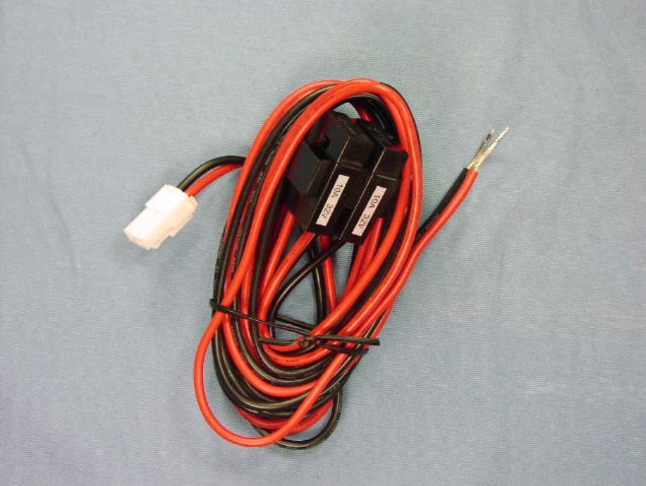
AXI11143030
Dec 07, 2014VHF MOBILE TWO-WAY RADIO
Equipment Class
TNB - Licensed Non-Broadcast Station Transmitter