AXI112846202-WAY PORTABLE RADIO
Vertex Standard USA, Inc.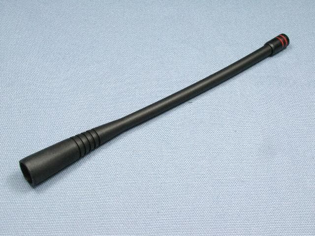
Click to zoom
Application Details
- Equipment Class
- TNF - Licensed Non-Broadcast Transmitter Held to Face
- Date of Grant
- Jun 30, 2015
- Application Purpose
- Original Equipment
- Date of Application
- Jun 30, 2015
- Equipment Note
- 2-WAY PORTABLE RADIO
- Frequency Range
- 403.00000000 - 470.00000000
- Company
- Vertex Standard USA, Inc.
- Country
- United States
Documents & Files
Document Text
Text extracted from the exhibit documents filed with the FCC. Open a document above to read the original.
Users Manual
Programmable Functions / Features IP55 Water Resistant Two Programmable Function Keys 2-Tone Encode/Decode 5-Tone Encode/Decode MDC-1200 ® Encode ( ANI Encode ) DTMF Encode Scan Dual Watch Follow-Me Scan Talk Around Scan VOX Talk Around Emergency Lone Worker TX Save Disable Lock ARTS™ ( Auto Range Transpond System ) VX-261 oPerating manual FCC ID: AXI11284620 IC: 10239A-11284620 Vertex Standard LMR, Inc. Introduction......................................................................1 Warning!.FCC.RF.Exposure.Requirements..................2 Warning!.IC.RSS.General.Requirement.......................4 Before.You.Begin..............................................................6 Battery Pack Installation and Removal .......................6 Battery Charging .........................................................6 Low Battery Indication ................................................7 Belt Clip Installation and Removal .............................8 MIC/SP Cap Installation .............................................8 Controls.&.Connectors....................................................9 Operation........................................................................10 Preliminary Steps ......................................................10 Operation Quick Start ................................................10 Automatic Time-Out Timer .......................................12 Advanced.Operation......................................................13 Programmable Key Functions ..................................13 Description of Operating Functions .........................14 Lock.................................................................................19 ARTS™. ( Auto.Range.Transpond.System ) ..................19 Optional.Accessories......................................................20 contents Congratulations! You now have at your fingertips a valuable communications tool, a Vertex Standard two-way radio! Rugged, reliable and easy to use, your Vertex Standard radio will keep you in constant touch with your colleagues for years to come, with negli- gible maintenance down-time. Please take a few minutes to read this manual carefully. The information presented here will allow you to derive maximum performance from your radio, in case questions arise later on. Important.Note r There are no owner-serviceable parts inside the radio. All service jobs must be referred to an authorized Vertex Standard Service Representative. r In order to maintain the specified water integrity performance, periodic maintenance is recommended. r Should the radio sustain a severe shock (e.g. if it is dropped), the water integrity may be compromised, requiring service. Should this occur, contact your Authorized Vertex Standard Dealer. FCC ID: AXI11284620 IC: 10239A-11284620 Vertex Standard LMR, Inc. VX-261 Operating Manual1 Important.Notice.for.North.American.Users.Regarding.406.MHz.Guard.Band The U.S. Coast Guard and National Oceanographic and Atmospheric Administration have requested the cooperation of the U.S. Federal Communications Commission in preserving the integrity of the protected frequency range 406.0 to 406.1 MHz, which is reserved for use by distress beacons. Do not attempt to program this apparatus, under any circumstances, for operation in the frequency range 406.0 - 406.1 MHz if the apparatus is to be used in or near North America. Warning - Frequency band 406 - 406.1 MHz is reserved for use ONLY as a distress beacon by the US Coast Guard and NOAA. Under no circumstance should this frequency band be part of the pre programmed operating frequencies of this radio. introduction The VX-261 is full-featured Hand-Held Analog Transceiver designed for business communications in the VHF/UHF Land Mobile bands. This transceiver is designed for reliable business communications in a wide variety of applications with a wide range of operating capability provided by their leading-edge design, and allows up to 16-channel capacity. Important channel frequency data is stored in the flash memory, and is easily programmable by a Vertex Standard licensed dealers using a personal computer with Vertex Standard Programming equipment: FIF-12 USB Programming Interface, and CT-106 Connection cable with CE150 Software. Or, once a single radio is programmed, cloning cable CT-27 can be used to program additional radios directly. This manual will describe the details of the many advanced features of the VX-261 . After reading this manual, you may wish to consult with your Network Administrator regarding precise details of the configuration of this equipment for use in your application. FCC ID: AXI11284620 IC: 10239A-11284620 Vertex Standard LMR, Inc. 2VX-261 Operating Manual Warning! Fcc rF exPosure requirements This Radio has been tested and complies with the Federal Communications Commission (FCC) RF exposure limits for Oc- cupational Use/Controlled exposure environment. In addition, it complies with the following Standards and Guidelines: r FCC 96-326, Guidelines for Evaluating the Environmental Effects of Radio-Frequency Radiation. r FCC OET Bulletin 65 Edition 97-01 (2001) Supplement C, Evaluating Compliance with FCC Guidelines for Human Exposure to Radio Frequency Electromagnetic Fields. r ANSI/IEEE C95.1-1992, IEEE Standard for Safety Levels with Respect to Human Exposure to Radio Frequency Elec- tromagnetic Fields, 3 kHz to 300 GHz. r ANSI/IEEE C95.3-1992, IEEE Recommended Practice for the Measurement of Potentially Hazardous Electromagnetic Fields - RF and Microwave. .WARNING: This radio generates RF electromagnetic energy during transmit mode. This radio is designed for and classified as Occupational Use Only, meaning it must be used only during the course of employment by individuals aware of the hazards, and the ways to minimize such hazards. This radio is not intended for use by the General Population in an uncontrolled environment. .CAUTION: To ensure that your…
Text truncated - open the document above for the full version.
Attestation Statements
February 3, 2015 Federal Communications Commission Authorization and Evaluation Division, 7435 Oakland Mills Road Columbia, MD 21046 USA Re: FCC ID: AXI11284620 Model: VX-261-G6-5 Gentlemen: The equipment meets the requirements of the FCC Rules, Part 90.203(e) and (g), as applicable. Programming of this product’s transmit frequencies can be performed only by the manufacturer or by service or maintenance personal. The operator cannot be program transmit frequencies using the equipment’s external operation controls. Sincerely, Vertex Standard LMR, Inc. Yukimasa Tomita Executive Manager
Cover Letter(s)
FCC ID: AXI11284620 VERTEX STANDARD USA, INC. Exhibit 13b 8000 West Sunrise Boulevard, Fort Lauderdale, Florida 33322 CONFIDENTIALITY REQUESTED Date: March 4, 2015 Office of Engineering and Technology Laboratory Division Equipment Authorization Branch Federal Communications Commission Laboratory 7435 Oakland Mills Road Columbia, MD 21046 Subject: Confidentiality Request Regarding Application for Transmitter with FCC ID: AXI11284620 Dear Sir or Madam: Vertex Standard USA, Inc. (8000 West Sunrise Boulevard, Fort Lauderdale, Florida) is requesting for the following Exhibits be held as Permanently Confidential, and not be made routinely available for public inspection: Block diagram Circuit diagram The information in these exhibits considers to be classified as trade secrets, pursuant to 47 CFR Sections 0.457(d), 0.459 and 552(b)(4) of the Freedom of Information Act. Please mark these Exhibits as “Confidential.” Please contact me if you require any additional information. Sincerely, Kim Uong Regulatory Compliance Engineer Tel: (954) 723-5422 E-mail: [email protected]
Cover Letter(s)
FCC ID: AXI11284620 VERTEX STANDARD USA, INC. Exhibit 13a 8000 West Sunrise Boulevard, Fort Lauderdale, Florida 33322 Date: March 4, 2015 Office of Engineering and Technology Laboratory Division Equipment Authorization Branch Federal Communications Commission Laboratory 7435 Oakland Mills Road Columbia, MD 21046 Subject: Extended Frequencies Justification for Certification of Transmitter with FCC ID: AXI11284620 Dear Sir or Madam: This transmitter was design to operate in the frequency range of 403-470 MHz. To aid equipment authorization in other countries that accept the United States FCC Grant for Certification, Vertex Standard USA Inc is requesting that the FCC list the above frequency/frequencies under FCC Rule Part 90 on the Grant. For the FCC’s Rule Part 90 application, this radio is used in systems by Federal and Public Safety agencies including Police, Fire, and Emergency Medical Services, etc. as indicated in the table below. Equipment programming is the responsibility of Authorized Service Personnel. Also, the radio complies with 47 CFR Part 90.203(e), in that the operator cannot directly program the transmit frequencies using the normally accessible external controls. Per the FCC’s KDB634817 guidance, as an alternative to listing the exact frequencies, we acknowledge that it’s a violation of the FCC Rules if this device operates on unauthorized frequencies. Frequency Range (MHz) Part 90 Emission Designator 403-406.1 11K0F3E 406.1-454 x 454-456* 456-459.025 x 459.025-459.650 x 459.650-462.5375 x 462.5375-462.7375* 462.7375-467.5375 x 467.5375-467.7375* 467.7375-470 x *Canada Please contact me if you require any additional information. Sincerely, Kim Uong Regulatory Compliance Engineer Tel: (954) 723-5422 E-mail: [email protected]
Cover Letter(s)
Federal Communications Commission Washington, D.C. 20554 June 26, 2015 DA 15-754 Yukimasa Tomita Executive Manager Vertex Standard LMR, Inc. 4-6-8 Shibaura Minato-ku, Tokyo 108-0023 Japan Re: Request for Waiver of Vertex Standard LMR, Inc. Dear Mr. Tomita: This letter addresses the request you filed on behalf of Vertex Standard LMR, Inc. (Vertex) for a waiver of the requirement Section 90.203(j)(5) of the Commission’s rules 1 that all Part 90 certification applications in specified VHF and UHF bands include a 6.25 kHz operating mode or equivalent efficiency. 2 Vertex seeks this waiver for equipment certification applications for two 5 watt 12.5 kHz UHF radios that are not capable of operating in a 6.25 kHz operating mode. 3 For the reasons set forth below, we grant the request. Background.Section 90.203(j)(5) of the Commission’s Rules states that applications for Part 90 certification of transmitters designed to operate in certain VHF/UHF bands filed on or after January 1, 2011 must be capable of meeting a spectrum efficiency standard of one voice channel per 6.25 kHz of channel bandwidth or equivalent efficiency. In 2010, the Commission temporarily waived this requirement until January 1, 2013. 4 In 2013, the Wireless Telecommunications Bureau, the Public Safety and Homeland Security Bureau, and the Office of Engineering and Technology (collectively the Bureaus) extended the waiver until January 1, 2015. 5 The requirement that applications for certification of Part 90 private land mobile radio equipment in the 150-174 MHz and 421-512 MHz bands include acertification that the equipment can operate in a 6.25 kHz mode or with equivalent efficiency is now in effect. Vertex states that it successfully completed and submitted applications for four out of six products in a new product line, without 6.25 kHz capability, prior to the January 1, 2015 1 See47 C.F.R. § 90.203(j)(5). 2 SeeRequest for Waiver of Vertex Standard LMR, Inc., filed Apr. 30, 2015 (Waiver Request); see also Request for Waiver of Vertex Standard LMR, Inc., filed Mar. 5, 2015. 3 FCC IDs AXI11274620 and AXI11284620. 4 See Implementation of Sections 309(j) and 337 of the Communications Act of 1934 as Amended, Order, WT Docket No. 99-87, 25 FCC Rcd 8861, 8866 ¶ 11 (2010). 5 SeeImplementation of Sections 309(j) and 337 of the Communications Act of 1934 as Amended, Order, WT Docket No. 99-87, 28 FCC Rcd 2811, 2814 ¶ 12 (WTB/PSHSB/OET 2013). Vertex Standard LMR, Inc.Page 2 deadline. 6 With respect to the other two models, it explains that it submitted equipment to the test facility early enough for an application to be submitted before the deadline, but the test facility unexpectedly requested additional material, which delayed the completion of the testing. 7 Because of this delay, Vertex was unable to submit equipment approval applications for these two models before January 1, 2015. A waiver is therefore sought for the two remaining models in the product line without 6.25 kHz capability. Discussion. To obtain a waiver of the Commission’s rules a petitioner must demonstrate either that (i) the underlying purpose of the rule(s) would not be served or would be frustrated by application to the present case, and that a grant of the waiver would be in the public interest; 8 or (ii) in view of unique or unusual factual circumstances of the instant case, application of the rule(s) would be inequitable, unduly burdensome, or contrary to the public interest or the applicant has no reasonable alternative. 9 We conclude that Vertex has presented sufficient facts to meet the high standard for grant of the requested waiver under the second prong of the waiver standard. Vertex has shown diligence in planning and has invested substantial resources in its new product line. If the waiver were denied, Vertex would continue to market its existing products without 6.25 kHz capability, but, according to Vertex, “rejecting the waiver request would denyusers the benefit of using radios with improved performance and design. It would also require Vertex Standard to develop new devices to replace the VX-264-G6-5 and VX-261-G6-5 outside of the company’s typical development cycles.” 10 Moreover, users seeking 6.25 kHz capability can obtain such equipment from Vertex and other manufacturers. 11 Accordingly, we grant Vertex Standard a waiver of the requirement that all Part 90 certification applications in specified UHF and VHF bands include a 6.25 kHz operatingmode, or equivalent efficiency. Accordingly, IT IS ORDERED pursuant to Section 4(i) of the Communications Act of 1934, as amended, 47 U.S.C. § 154(i), and Section 1.925(b)(3)(ii) of the Commission’s rules, 47 C.F.R.§ 1.925(b)(3)(ii), that the Request forWaiver, filed on April 30, 2015 by Vertex Standard LMR, Inc. IS GRANTED. 6 SeeWaiver Request at 2. 7 Id. 8 47 C.F.R. § 1.925(b)(3)(i). 9 47 C.F.R. § 1.925(b)(3)(ii). 10 Waiver Request at 3. 11 See id. Vertex Standard LMR, Inc.Page 3 This action is taken under delegated authority pursuant to Sections 0.131, 0.191, 0.331, and 0.392 of the Commission’s rules, 47 C.F.R. §§ 0.131, 0.191, 0.331, 0.392. FEDERAL COMMUNICATIONS COMMISSION Scot Stone Deputy Chief, Mobility Division Wireless Telecommunications Bureau Michael J. Wilhelm Deputy Chief, Policy and Licensing Division Public Safety and Homeland Security Bureau
External Photos
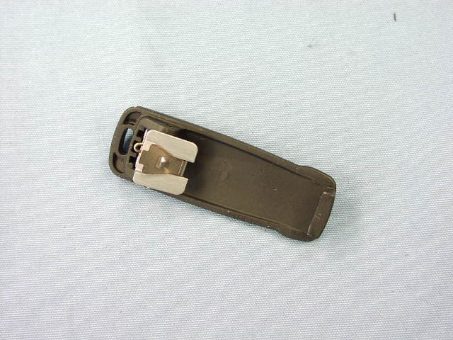
FCC ID: AXI11284620 IC: 10239A-11284620 Vertex Standard LMR, Inc. Front view with antenna Front view FCC ID: AXI11284620 IC: 10239A-11284620 Vertex Standard LMR, Inc. Rear view Rear view without Battery FCC ID: AXI11284620 IC: 10239A-11284620 Vertex Standard LMR, Inc. Left side Right side FCC ID: AXI11284620 IC: 10239A-11284620 Vertex Standard LMR, Inc. Top Bottom FCC ID: AXI11284620 IC: 10239A-11284620 Vertex Standard LMR, Inc. Battery Pack FNB-V133LI -UNI(1350mAh) and FNB-V134LI-UNI (2250mAh) Battery Charger FCC ID: AXI11284620 IC: 10239A-11284620 Vertex Standard LMR, Inc. AC Adapter Speaker/Microphone MH-45B4B FCC ID: AXI11284620 IC: 10239A-11284620 Vertex Standard LMR, Inc. Speaker/Microphone MH-360S Speaker/Microphone MH-450S FCC ID: AXI11284620 IC: 10239A-11284620 Vertex Standard LMR, Inc. Earpiece Microphone MH-37A4B Antenna FCC ID: AXI11284620 IC: 10239A-11284620 Vertex Standard LMR, Inc. Belt Clip Installation View of Belt Clip (Bottom)
ID Label/Location Info
VX-261-G6-5VX-261-G6-5 LABEL DRAWINGLABEL DRAWING Vertex Standard LMR, Inc.Vertex Standard LMR, Inc. ID / Part 15.19 and CAUTION drawings ID drawing Part 15.19 and CAUTION drawings Label location 2015. 1. 282015. 1. 28 VX-261-G6-5 FCC ID: AXI11284620 78026600120 VERTEX STANDARD LMR,INC. ASSEMBLED IN CHINA 27xxxxxxxx SER. NO. 7.4V IC:10239A-11284620 DESIGNED IN JAPAN FCC ID: AXI11284620 IC: 10239A-11284620 2A
Internal Photos
FCC ID: AXI11284620 IC: 10239A-11284620 Vertex Standard LMR, Inc. Side-A of MAIN-UNIT with Shield Side-A of MAIN-UNIT without Shield FCC ID: AXI11284620 IC: 10239A-11284620 Vertex Standard LMR, Inc. Side-B of MAIN-UNIT Inside of front panel FCC ID: AXI11284620 IC: 10239A-11284620 Vertex Standard LMR, Inc. Inside of chassis Outside of chassis FCC ID: AXI11284620 IC: 10239A-11284620 Vertex Standard LMR, Inc. PWB of Battery Charger
Operational Description
Circuit Description 1. Receiver System 1-1. Front-end RF amplifier Incoming RF signal from the antenna is delivered to the Main Unit and passes through low-pass filter, antenna switching diode D1004 and D1005 (both 1SS390 ), high- pass filter and removed undesired frequencies by varactor tuned band-pass filter D1007 and D1009 (both 1SV325 ). The filtered RF signal is amplified by Q1015 ( BFS505 ) and then passes through another varactor tuned band-pass filter D1013 and D1014 (both 1SV325 ) to remove the undesired frequencies, and then applied to the 1st mixer Q1020 ( 3SK293 ). 1-2. First Mixer The RF signal is mixed with the 1st local signal be- tween 352.15 and 419.15 MHz (Type “G6”) or 399.15 and 469.15 MHz (Type “G7”) in the 1st mixer Q1020 ( 3SK293 ), to produce 50.85 MHz 1st IF signal. The 1st local signal is generated by the VCO, which consists of Q1029 ( CPH3910 ), varactor diodes D1021, D1022, D1023, and D1025 (all 1SV325 ). The 1st lo- cal signal is supplied to the 1st mixer Q1020 ( 3SK293 ) through the buffer amplifier Q1021 and Q1026 (both 2SC5010 ). 1-3. IF Amplifier & Demodulator The 1st IF signal passes through monolithic crystal filters XF1001 (±7.5 kHz BW) to strip away all but the desired signal, and then supplied the buffer amplifier Q1035 ( 2SC5226 ). The amplified 1st IF signal is applied to the FM IF subsys- tem IC Q1040 ( AA32416 ) which contains the 2nd mixer, 2nd local oscillator, limiter amplifier, noise amplifier, and RSSI amplifier. The signal from reference oscillator X1002 (16.8 MHz) becomes three times of frequencies in Q1040 ( AA32416 ), it is mixed with the 1st IF signal and becomes 450 kHz. The 2nd IF signal passes through the ceramic filter CF1001 ( LTM450GW ) or CF1002 ( LTM450EW ) to strip away unwanted mixer products, and is supplied to the limiter amplifier in Q1040 ( AA32416 ), which removes amplitude variations in the 450 kHz IF, before detection of the speech by the ceramic discriminator CD1001 ( JT- BM450CX24 ). 1-4. Audio amplifier The detected signal from Q1040 ( AA32416 ) is supplied to the AF adder Q1045-1 ( NJM12902V ) through the TX/ RX switch Q1057-2 ( SN74LV4066A ), high-pass filter Q1045-2 ( NJM12902V ), and mute switch Q1057-4 ( SN74LV4066A ). The audio signal from Q1045-1 ( NJM12902V ) is sup- plied to the audio amplifier Q1008 ( TDA2822L ) through the AF volume potentiometer (VR1001). As a result, the audio signal provides up to 700 mW (@16-ohm BTL) for internal speaker or up to 500 mW (@4-ohm OTL) for ex- ternal speaker. 1-5. Squelch Circuit There are 16 levels of squelch setting from “0” to “15”. The level “0” means open the squelch. The level “1” means the threshold setting level and level “14” means tight squelch. From level “2” to level “13” is established in the middle of threshold and tight. The level “15” be- comes setting of carrier squelch. 1-5-1. Noise Squelch The noise squelch circuit is consisted of the band-path fil- ter, noise amplifier Q1047 ( 2SC4617 ), and noise detector D1035 ( DA221 ). When a carrier isn’t received, the noise ingredient which goes out of the demodulator section of Q1040 ( AA32416 ) is amplified by noise amplifier Q1047 ( 2SC4617 ) through the band-path filter, and then is detected to DC voltage by D1035 ( DA221 ). The DC voltage is inputted to pin 54 (A/D port) of the CPU Q1028 ( R5F100LHDFB ). When a carrier is received, the DC voltage becomes low because the noise is compressed. When the detected voltage to CPU is “High”, the CPU stops the AF output of Q1013 ( DTC144EE ) by making to “low” of the pin 39 of CPU. When the detection voltage to CPU is “low”, the CPU al- lows the AF output of Q1013 ( DTC144EE ) by making to “High” of the pin 39 of CPU. 1-5-2. Carrier Squelch The detected RSSI voltage from pin 12 of Q1040 ( AA32416 ) supplied to pin 53 (A/D port) of Q1028 ( R5F100LHDFB ). It is controls the AF output. The RSSI output voltage changes according to the signal strength of carrier. The stronger signal makes the RSSI voltage to be higher voltage. The process of the AF signal control is same as Noise Squelch. The shipping data is ad- justed 3 dBμ (EMF) higher than squelch tight sensitivity. FCC ID: AXI11284620 IC: 10239A-11284620 Vertex Standard LMR, Inc. 2. Transmitter System 2-1. MIC Amplifier The speech signal from internal microphone MC1001 or external microphone J1003 is amplified by Q1044-2 ( NJM12902V ). The amplified speech signal from Q1044-2 ( NJM12902V ) is supplied to pin 14 of Electric Volume IC Q1018 ( AK2330 ) which adjusts the microphone gain through the TX/RX switch Q1057-2 ( SN74LV4066A ), high-pass filter Q1045-2 ( NJM12902V ), and other TX/RX switch Q1057-3 ( SN74LV4066A ). The adjusted speech signal is output from pin 15 of Q1018 ( AK2330 ), and then passed through the limiter ampli- fier Q1044-1 ( NJM12902V ), low-pass filter Q1044-2/-3 ( NJM12902V ), and AF adder Q1052-3 ( NJM12902V ). The processed speech signal from Q1052-3 ( NJM12902V ) is supplied to pin 22 of Electric Volume IC Q1018 ( AK2330 ) which adjusts the maximum devia- tion. The adjusted speech signal is amplified by Q1052- 2 ( NJM12904R ), and then is made FM modulation to transmit carrier by the modulator D1019 ( BB208 ) of VCO Q1037 ( 2SC4227 ). 2-2. Drive and Final Amplifier Stages The modulated signal from the VCO Q1037 ( 2SC4227 ) is buffered by Q1026 ( 2SC5010 ). Then the signal is buffered by Q1021 ( 2SC5010 ) and Q1019 ( 2SK3077 ) for the driver amplifier Q1016 ( RQA0004PXDQS ). The low-level transmit signal is then applied to Q1012 ( RQA- 0011DNS ) for final amplification up to 5 watts output power. The transmit signal then passes through the antenna switch D1003 ( RN1425 ) and is low-pass filtered to sup- press away harmonic spurious radiation before delivery to the antenna. 2-3. Automatic Transmit Power Control The current detector Q1053-1 ( NJM12902V ) detects the current of the driver amplifier Q1016 ( RQA0004PXDQS ) and final amplifier Q1012 ( RQA0011DNS ), and converts the current difference…
Text truncated - open the document above for the full version.
Parts List/Tune Up Info
1 FCC ID: AXI11284620/IC: 10239A-11284620 VX-261-G6-5Semi-Conductor Parts List Address Parts Code Device NameDescriptionTYP VAL D 2001 Q9000981 Surge Absorber 0603ESDA2-TR2 D 2003 G2070994 DiodeRN142S TE61 D 2004 G2071226 Diode1SS390 D 2005 G2071226 Diode1SS390 D 2006 G2070178 DiodeDA221 TL D 2007 G2070942 Diode1SV305(TPH3) D 2008 G2070178 DiodeDA221 TL D 2009 G2070942 Diode1SV305(TPH3) D 2010 G2070934 Diode1SS400G T2R D 2012 G2071004 Zener DiodeEDZ TE-61 3.9B D 2013 G2070942 Diode1SV305(TPH3) D 2014 G2070942 Diode1SV305(TPH3) D 2015 G2070174 DiodeDAN222 TL D 2016 G2070934 Diode1SS400G T2R D 2017 G2070934 Diode1SS400G T2R D 2018 G2070874 Zener DiodeUDZS TE-17 4.3B D 2019 G2071523 DiodeBB208-02, 115 D 2020 G2070934 Diode1SS400G T2R D 2021 G2071006 Diode1SV323(TPH3.F) D 2022 G2071006 Diode1SV323(TPH3.F) D 2023 G2071006 Diode1SV323(TPH3.F) D 2024 G2070178 DiodeDA221 TL D 2025 G2071006 Diode1SV323(TPH3.F) D 2026 G2071006 Diode1SV323(TPH3.F) D 2029 G2071006 Diode1SV323(TPH3.F) D 2030 G2071276 LEDFSL-1615055GR-ZC4 D 2031 G2070934 Diode1SS400G T2R D 2032 G2070174 DiodeDAN222 TL D 2033 G2070174 DiodeDAN222 TL D 2034 G2070934 Diode1SS400G T2R D 2035 G2070178 DiodeDA221 TL D 2036 G2070178 DiodeDA221 TL D 2037 G2070934 Diode1SS400G T2R Q 2001 G3070347 MOSFETRTM002P02(TAPE) Q 2002 G3346178R Transistor2SC4617 TL R Q 2003 G3070347 MOSFETRTM002P02(TAPE) Q 2004 G3070075 TransistorDTC144EE TL Q 2005 G3070075 TransistorDTC144EE TL Q 2006 G1094097 ICTAR5S50U(TE85L.F) Q 2007 G1092116 ICTC7S66FU(TE85R.F) Q 2008 G1094497 ICTDA2822L-S08-R Q 2009 G3070075 TransistorDTC144EE TL Q 2010 G3070347 MOSFETRTM002P02(TAPE) Q 2011 G4070015 MOSFETRTQ030P02 Q 2012 G3070392 MOSFETRQA0011DNS Q 2013 G3070075 TransistorDTC144EE TL Q 2014 G3117748R Transistor2SA1774 TL R Q 2015 G3070489 TransistorBFS505 Q 2016 G3070391 MOSFETRQA0004PXDQS Q 2017 G3070075 TransistorDTC144EE TL Q 2018 G1094583 ICAK2330-L Q 2019 G3830778 MOSFET2SK3077(TE85L,F) Q 2020 G4802938A FET3SK293(TE85L.F) Q 2021 G3350108 Transistor2SC5010-T1-A/YFB Vertex Standard LMR, Inc. 2 FCC ID: AXI11284620/IC: 10239A-11284620 VX-261-G6-5Semi-Conductor Parts List Address Parts Code Device NameDescriptionTYP VAL Q 2022 G3070225 TransistorDTC114TE TL Q 2023 G3070225 TransistorDTC114TE TL Q 2024 G1093606 ICS-80835CNMC-B8U-T2-G Q 2025 G1094096 ICTAR5S35U(TE85L.F) Q 2026 G3350108 Transistor2SC5010-T1-A/YFB Q 2027 G3070225 TransistorDTC114TE TL Q 2028 G1095503 ICR5F100LHDFB#V0 Q 2029 G3070486 FETCPH3910-TL-E Q 2030 G3070225 TransistorDTC114TE TL Q 2031 G3070225 TransistorDTC114TE TL Q 2032 G3350108 Transistor2SC5010-T1-A/YFB Q 2033 G3070074 TransistorDTA144EE TL Q 2034 G3070075 TransistorDTC144EE TL Q 2035 G3070420 Transistor2SC5226A-4-TL-E Q 2036 G3346178R Transistor2SC4617 TL R Q 2037 G3342278B Transistor2SC4227-T1 R32 Q 2038 G3070074 TransistorDTA144EE TL Q 2039 G1095485 ICBR93G86FVM-3TR Q 2040 G1094857 ICAA32416 Q 2041 G3340818 Transistor2SC4081 T106 Q 2042 G3070225 TransistorDTC114TE TL Q 2043 G3070225 TransistorDTC114TE TL Q 2044 G1093592 ICNJM12902V-TE1 Q 2045 G1093592 ICNJM12902V-TE1 Q 2046 G1094713 ICAK1541 Q 2047 G3346178R Transistor2SC4617 TL R Q 2048 G1093336 ICNJM12903R-TE1 Q 2049 G3070075 TransistorDTC144EE TL Q 2050 G3070075 TransistorDTC144EE TL Q 2051 G1093592 ICNJM12902V-TE1 Q 2052 G1093592 ICNJM12902V-TE1 Q 2053 G1093337 ICNJM12904R-TE1 Q 2055 G3070075 TransistorDTC144EE TL Q 2056 G3070075 TransistorDTC144EE TL Q 2057 G1093871 ICSN74LV4066APWR Q 2059 G3070075 TransistorDTC144EE TL Q 2062 G3346178R Transistor2SC4617 TL R Vertex Standard LMR, Inc.
Parts List/Tune Up Info
Introduction The VX-261 is carefully aligned at the factory for the specified performance across the frequency range speci- fied for each version. Realignment should therefore not be necessary except in the event of a component failure, or altering version type. All component replacement and service should be performed only by an authorized Vertex Standard representative, or the warranty policy may be void. The following procedures cover the sometimes critical and tedious adjustments that are not normally required once the transceiver has left the factory. However, if damage occurs and some parts subsequently are replaced, realign- ment may be required. If a sudden problem occurs during normal operation, it is likely due to component failure; realignment should not be done until after the faulty com- ponent has been replaced. We recommend that servicing be performed only by au- thorized Vertex Standard service technicians who are ex- perienced with the circuitry and fully equipped for repair and alignment. Therefore, if a fault is suspected, contact the dealer from whom the transceiver was purchased for instructions regarding repair. Authorized Vertex Standard service technicians realign all circuits and make complete performance checks to ensure compliance with factory specifications after replacing any faulty components. Those who do undertake any of the following alignments are cautioned to proceed at their own risk. Problems caused by unauthorized attempts at realignment are not covered by the warranty policy. Also, Vertex Standard reserves the right to change circuits and alignment pro- cedures in the interest of improved performance, without notifying owners. Under no circumstances should any alignment be attempt- ed unless the normal function and operation of the trans- ceiver are clearly understood, the cause of the malfunction has been clearly pinpointed and any faulty components replaced, and realignment determined to be absolutely necessary. The following test equipment (and thorough familiarity with its correct use) is necessary for complete realign- ment. Correction of problems caused by misalignment resulting from use of improper test equipment is not covered under the warranty policy. While most steps do not require all of the equipment listed, the interactions of some adjustments may require that more complex adjust- ments be performed afterwards. Do not attempt to perform only a single step unless it is clearly isolated electrically from all other steps. Have all test equipment ready before beginning, and follow all of the steps in a section in the order presented. Required Test Equipment R F Signal Generator with calibrated output level at 600 MHz Oscilloscope Deviation Meter (linear detector) In-line Wattmeter with 5 % accuracy at 600 MHz 50 Ohm RF Dummy Load with power rating 10 W at 600 MHz Regulated DC Power Supply (standard 7.5 V DC, 3 A) F requency Counter with 0.2 ppm accuracy at 600 MHz Audio Signal Generator AC Voltmeter DC Voltmeter UHF Sampling Coupler IBM ® PC/compatible Computer with Microsoft ® Win- dows ® 2000, XP, Vista or Windows7 V ertex Standard CE150 PC Programming Software V ertex Standard FIF-12 USB Programming Interface and CT-104A, CT-106, or CT-171 PC Programming Cable. V ertex Standard FRB-6 Tuning Interface Box and CT- 160 Connection Cable. V ertex Standard CN-3 (P/N: A08760001) Antenna Connector Alignment Preparation & Precautions A 50-Ohm RF Dummy Load and in-line wattmeter must be connected to the main antenna jack in all procedures that call for transmission, except where specified other- wise. Correct alignment is not possible with an antenna. Because of the BTL (Bridged Trans Less) Amplifier cir- cuit used in the VX-261, do not connect earth side of the speaker leads to chassis “ground”. After compl…
Text truncated - open the document above for the full version.
Contact Information
Applicant
Deanna Zakharia(Regulatory Compliance Manager)
Technical Contact
Timco Engineering, Inc.Cory Leverett
[email protected]888-472-2424
849 NW State Road 45 · Newberry · United States
Non-Technical Contact
Timco Engineering, Inc.Sharon Hoffman
[email protected]888-472-2424
Test Firm
Timco Engineering, Inc.Bruno Clavier
Technical Specifications
| # | Rule Parts | Frequency Range | Power Output | Emission | Tolerance |
|---|---|---|---|---|---|
| 1 | 90 | 403 MHz - 470 MHz | 5 W | 11K0F3E | 2.5000000000 ppm |
Other Applications from Vertex Standard USA, Inc.
AXI11274620
Jun 30, 20152-WAY PORTABLE RADIO
Equipment Class
TNF - Licensed Non-Broadcast Transmitter Held to Face
AXI11273020
Dec 28, 2014VHF HANDHELD LAND MOBILE RADIO
Equipment Class
TNF - Licensed Non-Broadcast Transmitter Held to Face
AXI11283020
Dec 28, 2014VHF HANDHELD LAND MOBILE RADIO
Equipment Class
TNF - Licensed Non-Broadcast Transmitter Held to Face
AXI11143030
Dec 07, 2014VHF MOBILE TWO-WAY RADIO
Equipment Class
TNB - Licensed Non-Broadcast Station Transmitter
AXI10654620
Dec 01, 20142 WAY PORTABLE RADIO
Equipment Class
TNF - Licensed Non-Broadcast Transmitter Held to Face